Aspire 5534 Service Guide
Page 7
...View 4 Closed Front View 5 Left View 6 Right View 6 Base View 7 Rear View 8 Indicators 8 TouchPad Basics 9 Using the Keyboard 10 Lock Keys and embedded numeric keypad 10 Windows Keys 11 Hot Keys 12 Special Keys 13 Hardware Specifications and Configurations 14 System Utilities 23...WinFlash Utility 36 Remove HDD/BIOS Password Utilities 37 Removing BIOS Passwords 38 Miscellaneous Utilities 39 Machine Disassembly and Replacement 43 Disassembly Requirements 43 Related Information 43 43 General Information 44 Pre-disassembly Instructions 44 Disassembly Process 44 External...
...View 4 Closed Front View 5 Left View 6 Right View 6 Base View 7 Rear View 8 Indicators 8 TouchPad Basics 9 Using the Keyboard 10 Lock Keys and embedded numeric keypad 10 Windows Keys 11 Hot Keys 12 Special Keys 13 Hardware Specifications and Configurations 14 System Utilities 23...WinFlash Utility 36 Remove HDD/BIOS Password Utilities 37 Removing BIOS Passwords 38 Miscellaneous Utilities 39 Machine Disassembly and Replacement 43 Disassembly Requirements 43 Related Information 43 43 General Information 44 Pre-disassembly Instructions 44 Disassembly Process 44 External...
Aspire 5534 Service Guide
Page 8
... LCD Module 112 Replacing the CPU 113 Replacing the Thermal Module 114 Replacing the Fan 116 Replacing the Mainboard 118 Replacing the I/O Board 121 Replacing the Bluetooth Module 123 Replacing the Media Board 124 Replacing the Speaker Modules 125 Replacing the Power Board 127 Replacing the Touchpad Bracket 128 Replacing the Button Board 130 Replacing the Upper Cover 131 Replacing the Keyboard 136 External...
... LCD Module 112 Replacing the CPU 113 Replacing the Thermal Module 114 Replacing the Fan 116 Replacing the Mainboard 118 Replacing the I/O Board 121 Replacing the Bluetooth Module 123 Replacing the Media Board 124 Replacing the Speaker Modules 125 Replacing the Power Board 127 Replacing the Touchpad Bracket 128 Replacing the Button Board 130 Replacing the Upper Cover 131 Replacing the Keyboard 136 External...
Aspire 5534 Service Guide
Page 9
... Problems 148 Power On Issue 149 No Display Issue 150 Random Loss of BIOS Settings 151 LCD Failure 152 Built-In Keyboard Failure 152 Touchpad Failure 153 Internal Speaker Failure 153 Internal Microphone Failure 155 HDD Not Operating Correctly 156 ODD Failure 157 USB...and BIOS Recovery 175 Clearing Password Check 175 BIOS Recovery by Crisis Disk 176 FRU (Field Replaceable Unit) List 177 Aspire 5534 Exploded Diagrams 178 Main Assembly 178 LCD Assembly 179 Aspire 5534 FRU List 180 Screw List 186 Model Definition and Configuration 188 Test Compatible Components 206 Windows...
... Problems 148 Power On Issue 149 No Display Issue 150 Random Loss of BIOS Settings 151 LCD Failure 152 Built-In Keyboard Failure 152 Touchpad Failure 153 Internal Speaker Failure 153 Internal Microphone Failure 155 HDD Not Operating Correctly 156 ODD Failure 157 USB...and BIOS Recovery 175 Clearing Password Check 175 BIOS Recovery by Crisis Disk 176 FRU (Field Replaceable Unit) List 177 Aspire 5534 Exploded Diagrams 178 Main Assembly 178 LCD Assembly 179 Aspire 5534 FRU List 180 Screw List 186 Model Definition and Configuration 188 Test Compatible Components 206 Windows...
Aspire 5534 Service Guide
Page 68
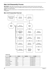
... components, ensure all available cable channels and clips are used and that the cables are replaced in the disassembly procedures may not represent the actual model. Main Unit Disassembly Flowchart Remove External Modules before proceeding Remove Keyboard Remove Upper Cover Upper Cover Remove Function Board Lower Cover Remove Right Speaker Module Remove...
... components, ensure all available cable channels and clips are used and that the cables are replaced in the disassembly procedures may not represent the actual model. Main Unit Disassembly Flowchart Remove External Modules before proceeding Remove Keyboard Remove Upper Cover Upper Cover Remove Function Board Lower Cover Remove Right Speaker Module Remove...
Aspire 5534 Service Guide
Page 70
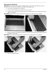
... or damaged during the removal process. Take care not to release the two tabs on page 46. 2. IMPORTANT: The use excessive force when removing the keyboard and replace if any damage occurs. 1. Removing the Keyboard IMPORTANT: The keyboard is still attached. 5. Turn the computer rightside up on the center of the...
... or damaged during the removal process. Take care not to release the two tabs on page 46. 2. IMPORTANT: The use excessive force when removing the keyboard and replace if any damage occurs. 1. Removing the Keyboard IMPORTANT: The keyboard is still attached. 5. Turn the computer rightside up on the center of the...
Aspire 5534 Service Guide
Page 146
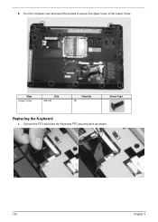
5. Connect the FFC and close the Keyboard FFC securing latch as shown. 136 Chapter 3 Step Upper Cover Size M2.5*8 Quantity 18 Screw Type Replacing the Keyboard 1. Turn the computer over and insert the screws to secure the Upper Cover to the Lower Cover.
5. Connect the FFC and close the Keyboard FFC securing latch as shown. 136 Chapter 3 Step Upper Cover Size M2.5*8 Quantity 18 Screw Type Replacing the Keyboard 1. Turn the computer over and insert the screws to secure the Upper Cover to the Lower Cover.
Aspire 5534 Service Guide
Page 162
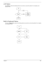
Do not replace a nondefective FRUs: Built-In Keyboard Failure If the built-in Keyboard fails, perform the following actions one at a time to correct the problem. Do not replace a non-defective FRUs: Chapter 4 152 LCD Failure If the LCD fails, perform the following actions one at a time to correct the problem.
Do not replace a nondefective FRUs: Built-In Keyboard Failure If the built-in Keyboard fails, perform the following actions one at a time to correct the problem. Do not replace a non-defective FRUs: Chapter 4 152 LCD Failure If the LCD fails, perform the following actions one at a time to correct the problem.
Aspire 5534 Service Guide
Page 222
Internal Microphone Failure 155 Internal Power Cable 80 Internal Speaker Failure 153 J Jumper and Connector Locations 173 Top View 173 K Keyboard Removing 60 Replacing 136 Keyboard Failure 152 L LCD Bezel Removing 91 Replacing 109 LCD Brackets Removing 98 Replacing 105 LCD Cable Removing 96, 107 LCD Failure 152 LCD Module Disassembly 90 Reassembly 103 Removing 84...
Internal Microphone Failure 155 Internal Power Cable 80 Internal Speaker Failure 153 J Jumper and Connector Locations 173 Top View 173 K Keyboard Removing 60 Replacing 136 Keyboard Failure 152 L LCD Bezel Removing 91 Replacing 109 LCD Brackets Removing 98 Replacing 105 LCD Cable Removing 96, 107 LCD Failure 152 LCD Module Disassembly 90 Reassembly 103 Removing 84...


