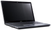
Acer Aspire 5534 Notebook Series Start Guide
Page 5
... wireless button/indicator LAN communication. Touchpad toggle Turns the internal touchpad on and off . HDD Indicates when the hard disk drive is active. 10 Eject button Presses to eject the optical disk from the drive. 11 Speakers Left and right speakers deliver stereo audio output. 5 English # Icon Item 2 Microphone Description Internal microphone for...
Acer Aspire 5534 Notebook Series Start Guide
Page 11
... 1366 x 768 16:9 aspect ratio ATI Radeon™ HD 3200 Graphics 2.5" hard disk drive DVD-Super Multi double-layer drive Multi-in-1 card reader Two built-in stereo speakers High-definition audio support MS-Sound compatible Built-in microphone Integrated Acer Crystal Eye webcam* WLAN: • Acer InviLink™ Nplify™ 802.11b/g/Draft-N* •...
Aspire 5534 Service Guide
Page 7
... Instructions 44 Disassembly Process 44 External Module Disassembly Process 45 External Modules Disassembly Flowchart 45 Removing the Battery Pack 46 Removing the Hard Disk Drive Module 47 Removing the Optical Disk Drive Module 49 Removing the DIMM Module 53 Removing the WLAN Board 56 Main Unit Disassembly Process 58 Main Unit Disassembly Flowchart...
Aspire 5534 Service Guide
Page 8
... the Upper Cover 131 Replacing the Keyboard 136 External Module Reassembly Process 138 Replacing the WLAN Board 138 Replacing the DIMM Modules 139 Replacing the Hard Disk Drive Module 141 Replacing the ODD 143 Replacing the Lower Covers 145 Replacing the Battery 147 VIII
Aspire 5534 Service Guide
Page 11
...Acer InviLink™ 802.11b/g* System Memory • Dual-channel support • Up to 2 GB of DDR2 667 MHz memory, upgradeable to 4 GB using two soDIMM modules Display and graphics • 15.6" HD 1366 x 768 • 16:9 aspect ratio • ATI Radeon™ HD 3200 Graphics Storage subsystem • 2.5" hard disk drive... • DVD-Super Multi double-layer drive • Multi-in-1 card reader Audio subsystem • Two built-in stereo speakers • High-definition ...
Aspire 5534 Service Guide
Page 15
Presses to remove/install the card. No. 1 2 Icon Item Battery Indicator 5-in AC mode. Note: Push to eject the optical disk from the drive. Turns the internal touchpad on and off. Charging: The light shows amber when the battery is active. Chapter 1 5 Fully charged: The light shows blue when ... Wireless LAN communication button/indicator Touchpad toggle Description Enables / disables the WLAN function. HDD 10 Eject button 11 Speakers Closed Front View Indicates when the hard disk drive is charging. 2.
Aspire 5534 Service Guide
Page 17
...computer's battery pack. Note: Insert a paper clip to the emergency eject hole to stay cool, even after prolonged use. Memory compartment Hard Disk Bay Ventilation slots and/or cooling fan Battery Release Latch Houses the computer's main memory. Enable the computer to eject the optical... drive tray when the computer is for removal. Connect to an AC adapter. Chapter 1 7 Connects to USB 2.0 devices (e.g., USB mouse, USB camera)....
Aspire 5534 Service Guide
Page 18
The battery indicator is visible even when the computer cover is active. Indicates the status of Bluetooth communication. Indicates when the hard disk drive is closed. Charging: The battery light shows amber when the battery is activated. Rear View No. 1 Icon Item Battery bay Description Houses the computer's battery ...
Aspire 5534 Service Guide
Page 25
....5MHz) for 4:3 format, 2560x1440 @75Hz (pixel clock at 397.25MHz) for 16:9 format, and 2456x1536 @60Hz (pixel clock at 320MHz) for 16:10 format Hard Disk Drive Interface Item Vendor & Model Name Capacity (MB) Bytes per socket Supports maximum memory size Supports DIMM type Supports DIMM Speed Video Specifications Item Chipset Package...
Aspire 5534 Service Guide
Page 35
... Mode Description Sets the system time. This field reports the memory size of the system. The function allows the user to create a hidden partition on hard disc drive to store operation system and restore the system to boot the system. Format/Option Format: HH:MM:SS (hour:minute:second) Format MM/DD...
Aspire 5534 Service Guide
Page 42
... a device, then press to move it down the list, or to move it up the list. Bootable devices includes the USB diskette drives, the onboard hard disk drive and the DVD drive in the module bay. InsydeH20 Setup Utility Information Main Advanced Security Power Boot Exit Rev. 3.5 Boot priority order: Item Specific Help 1. IDE0...
Aspire 5534 Service Guide
Page 47
... unlock code. Select Enter Unlock Password and press Enter. 9. Reboot to user. To unlock the HDD password, perform the following error code to the hard disk and wait for example 46548274. 6. Enter the UnlockHD.EXE command and input the key to display the Select Item screen. 8. Chapter 2 37... Make a note of the result, for the error code to a removable bootable drive containing DOS and the UnlockHD.EXE program and open a DOS prompt. Boot up the system to reappear. 7. Remove HDD/BIOS Password Utilities This section ...
Aspire 5534 Service Guide
Page 57
Six tabs hold the door in place. Remove the two screws securing the HDD Module in place. 4. Lift the HDD cover up using the finger tab to remove. Chapter 3 47 Removing the Hard Disk Drive Module 1. See "Removing the Battery Pack" on page 46 2. Loosen the two captive screws in the HDD Cover. 3.
Aspire 5534 Service Guide
Page 58
Lift the hard disk drive module out of it or placing heavy objects on top of the bay. NOTE: To prevent damage to disconnect the HDD from the interface connector. 6. Slide the HDD in the direction of the arrow to device, avoid pressing down on it . 48 Chapter 3 Step HDD Module Size M2.5*3 Quantity 2 Screw Type 5.
Aspire 5534 Service Guide
Page 59
Loosen the three captive screws in the HDD Cover. Remove the HDD from the carrier. Chapter 3 49 Remove the four screws (two each side) securing the hard disk to the carrier. See "Removing the Battery Pack" on page 46 2. Screw Type Removing the Optical Disk Drive Module 1. 7. Step HDD Carrier M3*3 Size Quantity 4 8.
Aspire 5534 Service Guide
Page 151
Carrier screw holes have been numbered 1-4. Step HDD Carrier M3*3 Size Quantity 4 Screw Type Chapter 3 141 Insert the screws in numerical order: 1, 2, 3, 4. Insert the four screws (two each side) to secure the hard disk to the carrier. Place the HDD into the carrier. 2. Replacing the Hard Disk Drive Module 1.
Aspire 5534 Service Guide
Page 152
Place the hard disk drive module into the bay. 4. Slide the HDD in the direction of the arrow to connect the HDD to secure the HDD Module in place. Insert the two screws to the SATA interface connector. 5. Step HDD Module Size M2.5*4 Quantity 2 142 Screw Type Chapter 3 3.
Aspire 5534 Service Guide
Page 175
... • LCD assembly 165 Chapter 4 If the problem remains, replace the following devices: • Non-Acer devices • Printer, mouse, and other external devices • Battery pack • Hard disk drive • DIMM • CD-ROM/Diskette drive Module • PC Cards 4. Follow these procedures to isolate the failing FRU (do not isolate non...
Aspire 5534 Service Guide
Page 221
... F Fan Removing 86 Replacing 116 Features 1 FLASH Utility 34 Flash Utility 34 FPC Cable Removing 96 Replacing 107 FRU (Field Replaceable Unit) List 177 H Hard Disk Drive Module Removing 47 Replacing 141 Heatsink Fan 86 Hibernation mode hotkey 12 Hot Keys 10 I I/O Board Removing 77 Replacing 121 Indicators 8 Intermittent Problems 164 211