
Acer Aspire 5534 Notebook Series Start Guide
Page 7
Note: Push to remove/install the card. Charging: The light shows amber when the battery is closed up. Fully charged: The light shows blue when in -1 card reader Accepts Secure Digital (SD), MultiMediaCard (MMC), Memory Stick (MS), Memory...Stick PRO (MS PRO), xDPicture Card (xD). 7 Closed front view English # Icon 1 2 Item Description Battery1 Indicates the computer's battery status. 1. Rear view # Icon 1 Item Battery bay Description Houses the computer's battery pack. Only one card can operate at any given time. 1. The front panel indicators are visible even when the computer...
Note: Push to remove/install the card. Charging: The light shows amber when the battery is closed up. Fully charged: The light shows blue when in -1 card reader Accepts Secure Digital (SD), MultiMediaCard (MMC), Memory Stick (MS), Memory...Stick PRO (MS PRO), xDPicture Card (xD). 7 Closed front view English # Icon 1 2 Item Description Battery1 Indicates the computer's battery status. 1. Rear view # Icon 1 Item Battery bay Description Houses the computer's battery pack. Only one card can operate at any given time. 1. The front panel indicators are visible even when the computer...
Acer Aspire 5534 Notebook Series Start Guide
Page 10
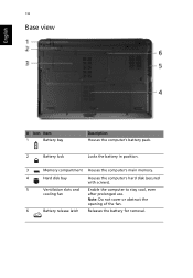
10 Base view English # Icon Item 1 Battery bay Description Houses the computer's battery pack. 2 Battery lock Locks the battery in position. 3 Memory compartment Houses the computer's main memory. 4 Hard disk bay Houses the computer's hard disk (secured with screws). 5 Ventilation slots and Enable the computer to stay cool, even cooling fan after prolonged use. Note: Do not cover or obstruct the opening of the fan. 6 Battery release latch Releases the battery for removal.
10 Base view English # Icon Item 1 Battery bay Description Houses the computer's battery pack. 2 Battery lock Locks the battery in position. 3 Memory compartment Houses the computer's main memory. 4 Hard disk bay Houses the computer's hard disk (secured with screws). 5 Ventilation slots and Enable the computer to stay cool, even cooling fan after prolonged use. Note: Do not cover or obstruct the opening of the fan. 6 Battery release latch Releases the battery for removal.
Aspire 5534 Service Guide
Page 7
... Pre-disassembly Instructions 44 Disassembly Process 44 External Module Disassembly Process 45 External Modules Disassembly Flowchart 45 Removing the Battery Pack 46 Removing the Hard Disk Drive Module 47 Removing the Optical Disk Drive Module 49 Removing the DIMM Module 53 Removing the WLAN Board 56 Main Unit Disassembly Process 58 Main Unit Disassembly Flowchart 58...
... Pre-disassembly Instructions 44 Disassembly Process 44 External Module Disassembly Process 45 External Modules Disassembly Flowchart 45 Removing the Battery Pack 46 Removing the Hard Disk Drive Module 47 Removing the Optical Disk Drive Module 49 Removing the DIMM Module 53 Removing the WLAN Board 56 Main Unit Disassembly Process 58 Main Unit Disassembly Flowchart 58...
Aspire 5534 Service Guide
Page 8
... Removing the Upper Cover 62 Removing the Button Board 66 Removing the Touchpad Bracket 68 Removing the Power Board 70 Removing the Speaker Modules 72 Removing the Media Board 74 Removing the Bluetooth Module 76 Removing the I/O Board 77 Removing the DC-In Cable 80 Removing the Mainboard 81 Removing the LCD Module 84 Removing the Fan 86 Removing the Thermal Module 88 Removing... Board 138 Replacing the DIMM Modules 139 Replacing the Hard Disk Drive Module 141 Replacing the ODD 143 Replacing the Lower Covers 145 Replacing the Battery 147 VIII
... Removing the Upper Cover 62 Removing the Button Board 66 Removing the Touchpad Bracket 68 Removing the Power Board 70 Removing the Speaker Modules 72 Removing the Media Board 74 Removing the Bluetooth Module 76 Removing the I/O Board 77 Removing the DC-In Cable 80 Removing the Mainboard 81 Removing the LCD Module 84 Removing the Fan 86 Removing the Thermal Module 88 Removing... Board 138 Replacing the DIMM Modules 139 Replacing the Hard Disk Drive Module 141 Replacing the ODD 143 Replacing the Lower Covers 145 Replacing the Battery 147 VIII

Aspire 5534 Service Guide
Page 15
... Secure Digital (SD), MultiMediaCard (MMC), Memory Stick (MS), Memory Stick PRO (MS PRO), xDPicture Card (xD). Presses to remove/install the card. No. 1 2 Icon Item Battery Indicator 5-in AC mode. Fully charged: The light shows blue when in -1 card reader Description Indicates the computer...'s battery status. 1. Only one card can operate at any given time. Charging: The light shows amber when the battery is active. Note: Push to eject the optical disk from the drive. No. 9...
... Secure Digital (SD), MultiMediaCard (MMC), Memory Stick (MS), Memory Stick PRO (MS PRO), xDPicture Card (xD). Presses to remove/install the card. No. 1 2 Icon Item Battery Indicator 5-in AC mode. Fully charged: The light shows blue when in -1 card reader Description Indicates the computer...'s battery status. 1. Only one card can operate at any given time. Charging: The light shows amber when the battery is active. Note: Push to eject the optical disk from the drive. No. 9...

Aspire 5534 Service Guide
Page 17
based network. Houses the computer's hard disk (secured with screws). No. 1 2 3 4 5 6 Icon Item Battery bay Battery lock Description Houses the computer's battery pack. Enable the computer to USB 2.0 devices (e.g., USB mouse, USB camera). Note: The battery shown is for removal. 3 4 5 6 Base View Emergency eject hole USB 2.0 port Ethernet (RJ-45) port DC-in position. Note: Do...
based network. Houses the computer's hard disk (secured with screws). No. 1 2 3 4 5 6 Icon Item Battery bay Battery lock Description Houses the computer's battery pack. Enable the computer to USB 2.0 devices (e.g., USB mouse, USB camera). Note: The battery shown is for removal. 3 4 5 6 Base View Emergency eject hole USB 2.0 port Ethernet (RJ-45) port DC-in position. Note: Do...
Aspire 5534 Service Guide
Page 54
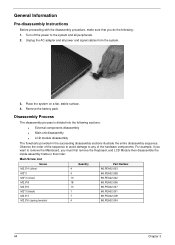
Disassembly Process The disassembly process is divided into the following : 1. Remove the battery pack. Main Screw List Screw M2.5*4 (silver) M3*3 M2*3 (silver) M2.5*8 M2.5*6 M2*3 (black) M2.5*3 M2.5*6 (spring tension) Quantity 4 4 10 18 13 1 7 4...009 86.PEA02.004 44 Chapter 3 General Information Pre-disassembly Instructions Before proceeding with the disassembly procedure, make sure that you must first remove the Keyboard, and LCD Module then disassemble the inside assembly frame in the succeeding disassembly sections illustrate the entire disassembly sequence. Unplug the ...
Disassembly Process The disassembly process is divided into the following : 1. Remove the battery pack. Main Screw List Screw M2.5*4 (silver) M3*3 M2*3 (silver) M2.5*8 M2.5*6 M2*3 (black) M2.5*3 M2.5*6 (spring tension) Quantity 4 4 10 18 13 1 7 4...009 86.PEA02.004 44 Chapter 3 General Information Pre-disassembly Instructions Before proceeding with the disassembly procedure, make sure that you must first remove the Keyboard, and LCD Module then disassemble the inside assembly frame in the succeeding disassembly sections illustrate the entire disassembly sequence. Unplug the ...

Aspire 5534 Service Guide
Page 55
External Modules Disassembly Flowchart Turn off system and peripherals power Disconnect power and signal cables from system Remove Battery Remove Dummy Card Remove Lower Covers Remove DIMMs Remove WLAN Remove HDD Remove ODD Screw List Step HDD Module HDD Carrier WLAN Board ODD Module ODD Bracket Screw M2.5*3 M3*3 M2*3 M2.5*3 M2*3 (silver) Quantity 2 4 1 1 2 Part No. 86....
External Modules Disassembly Flowchart Turn off system and peripherals power Disconnect power and signal cables from system Remove Battery Remove Dummy Card Remove Lower Covers Remove DIMMs Remove WLAN Remove HDD Remove ODD Screw List Step HDD Module HDD Carrier WLAN Board ODD Module ODD Bracket Screw M2.5*3 M3*3 M2*3 M2.5*3 M2*3 (silver) Quantity 2 4 1 1 2 Part No. 86....

Aspire 5534 Service Guide
Page 56
Turn the computer over. 2. Slide the battery lock/unlock latch to the release position (1), then slide out the battery pack from the main unit (2). 2 1 46 Chapter 3 Slide and hold the battery release latch to the unlock position. 3. Removing the Battery Pack 1.
Turn the computer over. 2. Slide the battery lock/unlock latch to the release position (1), then slide out the battery pack from the main unit (2). 2 1 46 Chapter 3 Slide and hold the battery release latch to the unlock position. 3. Removing the Battery Pack 1.

Aspire 5534 Service Guide
Page 57
Six tabs hold the door in the HDD Cover. 3. Loosen the two captive screws in place. 4. See "Removing the Battery Pack" on page 46 2. Chapter 3 47 Lift the HDD cover up using the finger tab to remove. Remove the two screws securing the HDD Module in place. Removing the Hard Disk Drive Module 1.
Six tabs hold the door in the HDD Cover. 3. Loosen the two captive screws in place. 4. See "Removing the Battery Pack" on page 46 2. Chapter 3 47 Lift the HDD cover up using the finger tab to remove. Remove the two screws securing the HDD Module in place. Removing the Hard Disk Drive Module 1.

Aspire 5534 Service Guide
Page 59
7. Step HDD Carrier M3*3 Size Quantity 4 8. Remove the HDD from the carrier. See "Removing the Battery Pack" on page 46 2. Screw Type Removing the Optical Disk Drive Module 1. Chapter 3 49 Remove the four screws (two each side) securing the hard disk to the carrier. Loosen the three captive screws in the HDD Cover.
7. Step HDD Carrier M3*3 Size Quantity 4 8. Remove the HDD from the carrier. See "Removing the Battery Pack" on page 46 2. Screw Type Removing the Optical Disk Drive Module 1. Chapter 3 49 Remove the four screws (two each side) securing the hard disk to the carrier. Loosen the three captive screws in the HDD Cover.

Aspire 5534 Service Guide
Page 63
... the cover in the Memory Cover. 3. Push out the release latches on page 46 2. Identify the SODIMM to remove. See "Removing the Battery Pack" on both sides of SODIMM slot 0 and SODIMM slot 1. Pull up to remove. The image below ) to release the memory module. Loosen the two captive screws in place. 4. Chapter 3 53...
... the cover in the Memory Cover. 3. Push out the release latches on page 46 2. Identify the SODIMM to remove. See "Removing the Battery Pack" on both sides of SODIMM slot 0 and SODIMM slot 1. Pull up to remove. The image below ) to release the memory module. Loosen the two captive screws in place. 4. Chapter 3 53...

Aspire 5534 Service Guide
Page 66
Use the finger tab to remove. NOTE: The HDD is White to the AUX terminal (right) and Black to the MAIN terminal (left). 56 Chapter 3 Disconnect the Antenna cables from the WLAN Board. NOTE: Cable placement is also located under this cover. 4. Loosen the two captive screws in place. Lift the HDD cover up to release the six clips securing the cover in the HDD Cover. 3. Removing the WLAN Board 1. See "Removing the Battery Pack" on page 46. 2.
Use the finger tab to remove. NOTE: The HDD is White to the AUX terminal (right) and Black to the MAIN terminal (left). 56 Chapter 3 Disconnect the Antenna cables from the WLAN Board. NOTE: Cable placement is also located under this cover. 4. Loosen the two captive screws in place. Lift the HDD cover up to release the six clips securing the cover in the HDD Cover. 3. Removing the WLAN Board 1. See "Removing the Battery Pack" on page 46. 2.
Aspire 5534 Service Guide
Page 70
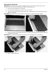
... two tabs on each side and lift the Keyboard away from the Upper Cover; the Keyboard FFC is easily warped or damaged during the removal process. Removing the Keyboard IMPORTANT: The keyboard is still attached. 5. Take care not to the full extent. 3. Pull up and open the lid ...of metal tools may damage the outer casing. IMPORTANT: Do not remove the Keyboard from the Upper Cover as shown. 60 Chapter 3 See "Removing the Battery Pack" on the center of the keyboard. IMPORTANT: The use excessive force when removing the keyboard and replace if any damage occurs. 1. Use plastic tools...
... two tabs on each side and lift the Keyboard away from the Upper Cover; the Keyboard FFC is easily warped or damaged during the removal process. Removing the Keyboard IMPORTANT: The keyboard is still attached. 5. Take care not to the full extent. 3. Pull up and open the lid ...of metal tools may damage the outer casing. IMPORTANT: Do not remove the Keyboard from the Upper Cover as shown. 60 Chapter 3 See "Removing the Battery Pack" on the center of the keyboard. IMPORTANT: The use excessive force when removing the keyboard and replace if any damage occurs. 1. Use plastic tools...
Aspire 5534 Service Guide
Page 160
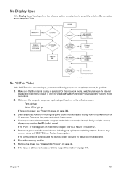
... power, see "Online Support Information" on page 149. 3. Chapter 4 150 On this model). If the computer boots correctly, add the devices one by removing the power cable and battery and holding down the power button for specific model procedures. 2. Reconnect the power and reboot the computer.... 4. Remove any stored power by one of the following occurs: • Fans start up • Status LEDs light up If there is still not resolved,...
... power, see "Online Support Information" on page 149. 3. Chapter 4 150 On this model). If the computer boots correctly, add the devices one by removing the power cable and battery and holding down the power button for specific model procedures. 2. Reconnect the power and reboot the computer.... 4. Remove any stored power by one of the following occurs: • Fans start up • Status LEDs light up If there is still not resolved,...
Aspire 5534 Service Guide
Page 161
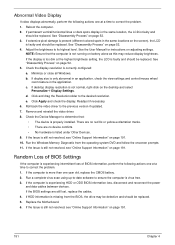
.... 5. Readjust if necessary. 6. There are no red Xs or yellow exclamation marks. • There are still lost, replace the cables. 4. Remove and reinstall the video driver. 8. If the Issue is listed under Other Devices. 9. Click Apply and check the display. If permanent vertical/horizontal ...lines or dark spots display in the same locations on battery alone as this may be defective and should be replaced. 5. Click and drag the Resolution slider to correct the problem. 1. Random...
.... 5. Readjust if necessary. 6. There are no red Xs or yellow exclamation marks. • There are still lost, replace the cables. 4. Remove and reinstall the video driver. 8. If the Issue is listed under Other Devices. 9. Click Apply and check the display. If permanent vertical/horizontal ...lines or dark spots display in the same locations on battery alone as this may be defective and should be replaced. 5. Click and drag the Resolution slider to correct the problem. 1. Random...
Aspire 5534 Service Guide
Page 174
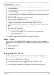
... program experiencing mouse failure. 5. Check the Device Manager to correct the problem. 1. Swap M/B to verify mouse operation. For more errors. Remove and reinstall the mouse driver. 12. Do not replace a non-defective FRUs: 1. Intermittent Problems Intermittent system hang problems can be considered only... to determine that: • The device is a good connection. If the mouse uses a wireless connection, insert new batteries and confirm there is properly installed. Run the Event Viewer to the previous version if updated recently. 11. See the mouse user manual...
... program experiencing mouse failure. 5. Check the Device Manager to correct the problem. 1. Swap M/B to verify mouse operation. For more errors. Remove and reinstall the mouse driver. 12. Do not replace a non-defective FRUs: 1. Intermittent Problems Intermittent system hang problems can be considered only... to determine that: • The device is a good connection. If the mouse uses a wireless connection, insert new batteries and confirm there is properly installed. Run the Event Viewer to the previous version if updated recently. 11. See the mouse user manual...
Aspire 5534 Service Guide
Page 175
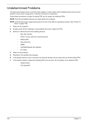
Power-off the computer. 2. If the problem does not recur, reconnect the removed devices one at a time. Follow these procedures to isolate the failing FRU (do not isolate non-defective FRU). NOTE: Verify that all of the following ... supply being used at a time until you find the failing FRU. 7. If the problem remains, replace the following devices: • Non-Acer devices • Printer, mouse, and other external devices • Battery pack • Hard disk drive • DIMM • CD-ROM/Diskette drive Module • PC Cards 4. Visually check them for...
Power-off the computer. 2. If the problem does not recur, reconnect the removed devices one at a time. Follow these procedures to isolate the failing FRU (do not isolate non-defective FRU). NOTE: Verify that all of the following ... supply being used at a time until you find the failing FRU. 7. If the problem remains, replace the following devices: • Non-Acer devices • Printer, mouse, and other external devices • Battery pack • Hard disk drive • DIMM • CD-ROM/Diskette drive Module • PC Cards 4. Visually check them for...
Aspire 5534 Service Guide
Page 185
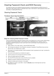
... door. 9. Check the Security screen shows Supervisor and User Passwords are clear. Aspire 5534 provides one Hardware Open Gap on password. Press and hold the power key to enter BIOS. Remove the battery pack and AC adapter. 7. Replace the battery pack and power on , the system prompts to input the password. After power... CMOS Jumper Location Memory Bay Steps for enabling BIOS Recovery. Enter the password set BIOS Password (Supervisor Password and/or User Password) for Aspire 5534. Open the memory door and remove the memory modules. 6. However, once it is complete). 8.
... door. 9. Check the Security screen shows Supervisor and User Passwords are clear. Aspire 5534 provides one Hardware Open Gap on password. Press and hold the power key to enter BIOS. Remove the battery pack and AC adapter. 7. Replace the battery pack and power on , the system prompts to input the password. After power... CMOS Jumper Location Memory Bay Steps for enabling BIOS Recovery. Enter the password set BIOS Password (Supervisor Password and/or User Password) for Aspire 5534. Open the memory door and remove the memory modules. 6. However, once it is complete). 8.
Aspire 5534 Service Guide
Page 221
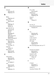
A Antennas Removing 101 Replacing 103 B Battery Replacing 147 Battery Pack Removing 46 BIOS ROM type 18 vendor 18 Version 18 BIOS Utility 23-34 Advanced 28 Boot 32 Exit 33 Navigating 23 Power 31 Save and Exit 33 Security 28 System Security 33 Bluetooth Module Removing 76 Replacing 123 Board Layout Top View 173 brightness hotkeys...
A Antennas Removing 101 Replacing 103 B Battery Replacing 147 Battery Pack Removing 46 BIOS ROM type 18 vendor 18 Version 18 BIOS Utility 23-34 Advanced 28 Boot 32 Exit 33 Navigating 23 Power 31 Save and Exit 33 Security 28 System Security 33 Bluetooth Module Removing 76 Replacing 123 Board Layout Top View 173 brightness hotkeys...


