Acer Aspire 5517 Notebook Series Quick Guide
Page 6
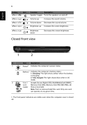
Brightness up Increases the sound volume. Fully charged: The light shows blue when in AC mode. 2 5-in-1 Accepts Secure Digital (SD), MultiMediaCard (MMC), card Memory Stick (MS), Memory Stick PRO (MS PRO), xD- Brightness down Decreases the sound volume. Charging: The light shows amber when the battery is closed up. The front panel...
Brightness up Increases the sound volume. Fully charged: The light shows blue when in AC mode. 2 5-in-1 Accepts Secure Digital (SD), MultiMediaCard (MMC), card Memory Stick (MS), Memory Stick PRO (MS PRO), xD- Brightness down Decreases the sound volume. Charging: The light shows amber when the battery is closed up. The front panel...
Acer Aspire 5517 Notebook Series Quick Guide
Page 9
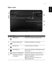
Note: Do not cover or obstruct the opening of the fan. 9 Base view English # Icon Item 1 Battery bay Description Houses the computer's battery pack. 2 Battery release latch Releases the battery for removal. 3 Battery lock Locks the battery in position. 4 Hard disk bay Houses the computer's hard disk (secured with screws). 5 Memory compartment Houses the computer's main memory. 6 Ventilation slots and Enable the computer to stay cool, even cooling fan after prolonged use.
Note: Do not cover or obstruct the opening of the fan. 9 Base view English # Icon Item 1 Battery bay Description Houses the computer's battery pack. 2 Battery release latch Releases the battery for removal. 3 Battery lock Locks the battery in position. 4 Hard disk bay Houses the computer's hard disk (secured with screws). 5 Memory compartment Houses the computer's main memory. 6 Ventilation slots and Enable the computer to stay cool, even cooling fan after prolonged use.
Acer Aspire 5517 Notebook Series Quick Guide
Page 10
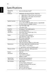
...-definition audio support MS-Sound compatible Integrated webcam* WLAN: IEEE 802.11b/g LAN: Fast Ethernet; 10 English Specifications Operating • system Platform • System memory • • Display • • Graphics • Storage • subsystem • • Audio • • • Communication •...core processor • AMD M780G Chipset • IEEE 802.11b/g Dual-channel support Up to 2 GB of DDR2 667 MHz memory, upgradeable to 4 GB using two soDIMM modules 15.6" HD 1366 x 768 16:9 aspect ratio ATI Radeon™ HD 3200 Graphics...
...-definition audio support MS-Sound compatible Integrated webcam* WLAN: IEEE 802.11b/g LAN: Fast Ethernet; 10 English Specifications Operating • system Platform • System memory • • Display • • Graphics • Storage • subsystem • • Audio • • • Communication •...core processor • AMD M780G Chipset • IEEE 802.11b/g Dual-channel support Up to 2 GB of DDR2 667 MHz memory, upgradeable to 4 GB using two soDIMM modules 15.6" HD 1366 x 768 16:9 aspect ratio ATI Radeon™ HD 3200 Graphics...
Acer Aspire 5517 Series Service Guide
Page 5
...requirements and enhance product competitiveness, your regional office MAY have a DIFFERENT part number code to -date information available on card, modem, or extra memory capability). Please note WHEN ORDERING FRU PARTS, that you should check the most up-to those given in the FRU list of this printed Service... Guide. You MUST use the list provided by your Acer office may have decided to order FRU parts for whatever reason, a part number change is made, it supports, please read the following general ...
...requirements and enhance product competitiveness, your regional office MAY have a DIFFERENT part number code to -date information available on card, modem, or extra memory capability). Please note WHEN ORDERING FRU PARTS, that you should check the most up-to those given in the FRU list of this printed Service... Guide. You MUST use the list provided by your Acer office may have decided to order FRU parts for whatever reason, a part number change is made, it supports, please read the following general ...

Acer Aspire 5517 Series Service Guide
Page 11
...; Vista™ Platform • AMD Athlon™ 64 X2 dual-core processor • AMD Athlon™ 64 single-core processor • AMD M780G Chipset System Memory • Low-latency, high-bandwidth • 128-bit DDR2 SDRAM controller operating at up to 333 MHz • On-board... up to 2 unbuffered SO-DIMM slots supporting DDR II 667/800. • Adjustable Maximum 128MB UMA VGA memory shared from North Bridge • Maximum memory: 2GB per slot; 4GB total • On-board cache up to 1MB Display • 15.6" WXGA, HD 720p, 1366x768 Graphics • ATI Radeon™ HD ...
...; Vista™ Platform • AMD Athlon™ 64 X2 dual-core processor • AMD Athlon™ 64 single-core processor • AMD M780G Chipset System Memory • Low-latency, high-bandwidth • 128-bit DDR2 SDRAM controller operating at up to 333 MHz • On-board... up to 2 unbuffered SO-DIMM slots supporting DDR II 667/800. • Adjustable Maximum 128MB UMA VGA memory shared from North Bridge • Maximum memory: 2GB per slot; 4GB total • On-board cache up to 1MB Display • 15.6" WXGA, HD 720p, 1366x768 Graphics • ATI Radeon™ HD ...
Acer Aspire 5517 Series Service Guide
Page 16
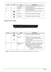
... the computer's battery status. 1. Fully charged: The light shows green when in AC mode. 2 Multi-in-1 card Accepts Secure Digital (SD), MultiMediaCard reader (MMC), Memory Stick (MS), Memory Stick PRO (MS PRO), xD-Picture Card (xD). Num Lock Caps Lock Lights up when Caps Lock is charging. 2. NOTE: 1 The front panel indicators...
... the computer's battery status. 1. Fully charged: The light shows green when in AC mode. 2 Multi-in-1 card Accepts Secure Digital (SD), MultiMediaCard reader (MMC), Memory Stick (MS), Memory Stick PRO (MS PRO), xD-Picture Card (xD). Num Lock Caps Lock Lights up when Caps Lock is charging. 2. NOTE: 1 The front panel indicators...
Acer Aspire 5517 Series Service Guide
Page 19
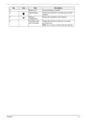
Chapter 1 9 Note: Do not cover or obstruct the fan opening. Houses the computer's main memory. Enable the computer to stay cool, even after prolonged use. Houses the computer's hard disk (secured with screws). No. 3 4 5 5 Icon Item Battery lock Hard disk bay Memory compartment Ventilation slots and cooling fan Description Locks the battery in position.
Chapter 1 9 Note: Do not cover or obstruct the fan opening. Houses the computer's main memory. Enable the computer to stay cool, even after prolonged use. Houses the computer's hard disk (secured with screws). No. 3 4 5 5 Icon Item Battery lock Hard disk bay Memory compartment Ventilation slots and cooling fan Description Locks the battery in position.
Acer Aspire 5517 Series Service Guide
Page 28
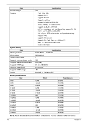
Item BIOS ROM type Features System Memory Item Memory controller Memory size DIMM socket number Supports memory size per socket Supports maximum memory size Supports DIMM type Supports DIMM Speed Supports DIMM voltage Cache Specification Flash • Flash ROM 1MB • Supports ISIPP • Supports Acer UI • Supports multi-boot...ATI SB710 4GB maximum 2 2GB 4GB (total) 200-pin +1.8V DDRII 667/800 MHz 1.8V Upto 1MB L2 Cache on CPU Memory Combinations Slot 1 0MB 0MB 0MB 512MB 512MB 512MB 1024MB 1024MB 1024MB 1024MB 2048MB 2048MB 2048MB 2048MB 512MB 1024MB 2048MB 512MB 1024MB 2048MB ...
Item BIOS ROM type Features System Memory Item Memory controller Memory size DIMM socket number Supports memory size per socket Supports maximum memory size Supports DIMM type Supports DIMM Speed Supports DIMM voltage Cache Specification Flash • Flash ROM 1MB • Supports ISIPP • Supports Acer UI • Supports multi-boot...ATI SB710 4GB maximum 2 2GB 4GB (total) 200-pin +1.8V DDRII 667/800 MHz 1.8V Upto 1MB L2 Cache on CPU Memory Combinations Slot 1 0MB 0MB 0MB 512MB 512MB 512MB 1024MB 1024MB 1024MB 1024MB 2048MB 2048MB 2048MB 2048MB 512MB 1024MB 2048MB 512MB 1024MB 2048MB ...

Acer Aspire 5517 Series Service Guide
Page 30
... 150 5V ±5% 8 MB SATA 395~952 (typical) 300 5V ±5% Super-Multi Drive Item Vendor & model name Performance Specification Transfer rate (MB/sec) Buffer Memory Interface HLDS GT20N With CD Diskette Specification Sony AD7580S With DVD Diskette With CD Diskette Sustained: Sustained: 3,600 KB/s (24x) max. 11.08 Mbytes/s (8x...
... 150 5V ±5% 8 MB SATA 395~952 (typical) 300 5V ±5% Super-Multi Drive Item Vendor & model name Performance Specification Transfer rate (MB/sec) Buffer Memory Interface HLDS GT20N With CD Diskette Specification Sony AD7580S With DVD Diskette With CD Diskette Sustained: Sustained: 3,600 KB/s (24x) max. 11.08 Mbytes/s (8x...

Acer Aspire 5517 Series Service Guide
Page 37
...video graphics. Enables, disables D2D Recovery function. Control the mode in this screen. Parameter System Time System Date System Memory Extended Memory Video Memory Quiet Boot Network Boot F12 Boot Menu D2D Recovery SATA Mode Description Sets the system time. Sets the system date....tests while booting, decreasing the time needed to boot the system. This field shows the memory allocated for your reference only. Information M a i n System Time: System Date: System Memory: Extended Memory: Video Memory: PhoenixBIOS Setup Utility Security Boot Exit [09:00:00] [12/12/2008] 634 ...
...video graphics. Enables, disables D2D Recovery function. Control the mode in this screen. Parameter System Time System Date System Memory Extended Memory Video Memory Quiet Boot Network Boot F12 Boot Menu D2D Recovery SATA Mode Description Sets the system time. Sets the system date....tests while booting, decreasing the time needed to boot the system. This field shows the memory allocated for your reference only. Information M a i n System Time: System Date: System Memory: Extended Memory: Video Memory: PhoenixBIOS Setup Utility Security Boot Exit [09:00:00] [12/12/2008] 634 ...
Acer Aspire 5517 Series Service Guide
Page 43
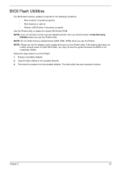
If the battery pack does not contain enough power to run the Phlash utility. The flash utility has auto-execution function. NOTE: Do not install memory-related drivers (XMS, EMS, DPMI) when you use the AC adaptor power supply when you run the Phlash. 1. NOTE: Please use the Phlash. Prepare a bootable ... the system from the bootable diskette. Copy the flash utilities to update the system BIOS flash ROM. Chapter 2 33 BIOS Flash Utilities The BIOS flash memory update is not completely loaded.
If the battery pack does not contain enough power to run the Phlash utility. The flash utility has auto-execution function. NOTE: Do not install memory-related drivers (XMS, EMS, DPMI) when you use the AC adaptor power supply when you run the Phlash. 1. NOTE: Please use the Phlash. Prepare a bootable ... the system from the bootable diskette. Copy the flash utilities to update the system BIOS flash ROM. Chapter 2 33 BIOS Flash Utilities The BIOS flash memory update is not completely loaded.
Acer Aspire 5517 Series Service Guide
Page 49
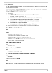
... 2 39 Execute dmitools. Write UUID to EEPROM Input: dmitools /ws 01234567890123456789 4 ). Read DMI Information from Memory Input: dmitools /r Output: Manufacturer (Type1, Offset04h): Acer Product Name (Type1, Offset05h): TravelMate xxxxx Serial Number (Type1, Offset07h): 01234567890123456789 UUID String (Type1, Offset08h): xxxxxxxx...-xxxx-xxxx-xxxx-xxxxxxxxxxxx Asset Tag (Type3, Offset04h): Acet Asstag Write Product Name to EEPROM Input: dmitools /wp Acer Write Serial Number to EEPROM ( Create UUID from bios • dmitools /wm xxxx ==> Write manufacturer name to eeprom (max...
... 2 39 Execute dmitools. Write UUID to EEPROM Input: dmitools /ws 01234567890123456789 4 ). Read DMI Information from Memory Input: dmitools /r Output: Manufacturer (Type1, Offset04h): Acer Product Name (Type1, Offset05h): TravelMate xxxxx Serial Number (Type1, Offset07h): 01234567890123456789 UUID String (Type1, Offset08h): xxxxxxxx...-xxxx-xxxx-xxxx-xxxxxxxxxxxx Asset Tag (Type3, Offset04h): Acet Asstag Write Product Name to EEPROM Input: dmitools /wp Acer Write Serial Number to EEPROM ( Create UUID from bios • dmitools /wm xxxx ==> Write manufacturer name to eeprom (max...
Acer Aspire 5517 Series Service Guide
Page 56
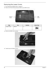
See "Removing the Battery Pack" on page 44. 2. Quantity 3 Screw Type 4. Carefully open the Memory Cover. 46 Chapter 3 Removing the Lower Covers 1. Remove the HDD cover as shown. Memory Cover HDD Cover Step Lower Covers Size M2.5*8 3. Remove the three screws securing the Memory and HDD Covers.
See "Removing the Battery Pack" on page 44. 2. Quantity 3 Screw Type 4. Carefully open the Memory Cover. 46 Chapter 3 Removing the Lower Covers 1. Remove the HDD cover as shown. Memory Cover HDD Cover Step Lower Covers Size M2.5*8 3. Remove the three screws securing the Memory and HDD Covers.

Acer Aspire 5517 Series Service Guide
Page 127
Push the ODD Module into the tray, bottom edge first, to the ODD Module. 3. Chapter 3 117 flush with the two screws. Secure the ODD bracket with the casing. Replace the HDD Cover as shown. 2. IMPORTANT: Press down around the perimeter of the covers to secure the Module. Replace the single screw to ensure that the all the securing tabs are correctly located in the casing. Press the bezel into the ODD bay until it to 2. secure it is 4. Replacing the Lower Covers 1. Replace the Memory Cover as shown. Replacing the ODD Module 1.
Push the ODD Module into the tray, bottom edge first, to the ODD Module. 3. Chapter 3 117 flush with the two screws. Secure the ODD bracket with the casing. Replace the HDD Cover as shown. 2. IMPORTANT: Press down around the perimeter of the covers to secure the Module. Replace the single screw to ensure that the all the securing tabs are correctly located in the casing. Press the bezel into the ODD bay until it to 2. secure it is 4. Replacing the Lower Covers 1. Replace the Memory Cover as shown. Replacing the ODD Module 1.

Acer Aspire 5517 Series Service Guide
Page 128
Memory Cover HDD Cover Replacing the SD Dummy Card 1. Insert the SD Dummy Card into place and is flush with the casing. 118 Chapter 3 Replace the three screws to secure the covers in place. 3. Push until the card clicks into the slot as shown. 2.
Memory Cover HDD Cover Replacing the SD Dummy Card 1. Insert the SD Dummy Card into place and is flush with the casing. 118 Chapter 3 Replace the three screws to secure the covers in place. 3. Push until the card clicks into the slot as shown. 2.
Acer Aspire 5517 Series Service Guide
Page 133
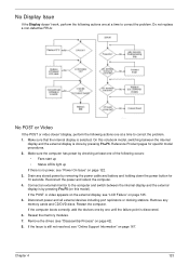
... power, see "LCD Failure" on page 122. 3. Make sure the computer has power by checking at a time to correct the problem. 1. Chapter 4 123 Drain any memory cards and CD/DVD discs. If the POST or video appears on the external display, see "Power On Issue" on page 125. 5. On this model... boots correctly, add the devices one by removing the power cable and battery and holding down the power button for specific model procedures. 2. Reseat the memory modules. 7.
... power, see "LCD Failure" on page 122. 3. Make sure the computer has power by checking at a time to correct the problem. 1. Chapter 4 123 Drain any memory cards and CD/DVD discs. If the POST or video appears on the external display, see "Power On Issue" on page 125. 5. On this model... boots correctly, add the devices one by removing the power cable and battery and holding down the power button for specific model procedures. 2. Reseat the memory modules. 7.

Acer Aspire 5517 Series Service Guide
Page 134
... the onscreen prompts. 11. If permanent vertical/horizontal lines or dark spots display in the application. See "Disassembly Process" on page 42. 4. Run the Windows Memory Diagnostic from the BIOS, the drive may reduce display brightness. If the computer is still not resolved, see "Online Support Information" on page 167. 124...
... the onscreen prompts. 11. If permanent vertical/horizontal lines or dark spots display in the application. See "Disassembly Process" on page 42. 4. Run the Windows Memory Diagnostic from the BIOS, the drive may reduce display brightness. If the computer is still not resolved, see "Online Support Information" on page 167. 124...

Acer Aspire 5517 Series Service Guide
Page 138
... more information see Windows Help and Support. 10. insert the Windows Vista Operating System DVD in the ODD and restart the computer. Run the Windows Memory Diagnostic Tool. Select Startup Repair. Restart the computer and press F2 to locate and resolve issues with the computer. For more information see Windows Help...
... more information see Windows Help and Support. 10. insert the Windows Vista Operating System DVD in the ODD and restart the computer. Run the Windows Memory Diagnostic Tool. Select Startup Repair. Restart the computer and press F2 to locate and resolve issues with the computer. For more information see Windows Help...

Acer Aspire 5517 Series Service Guide
Page 145
...describe the POST codes and descriptions during warm boot Initialize PCI Bus Mastering devices Initialize keyboard controller BIOS ROM checksum Initialize cache before memory autosize 8254 timer initialization 8237 DMA controller initialization Reset Programmable Interrupt Controller Test DRAM refresh Test 8742 Keyboard Controller Set ES segment ... IN POST flag Initialize CPU registers Enable CPU cache Initialize caches to 4 GB Enable A20 line Autosize DRAM Initialize POST Memory Manager Clear 512 KB base RAM RAM failure on address line xxxx* RAM failure on data bits xxxx* of low byte of...
...describe the POST codes and descriptions during warm boot Initialize PCI Bus Mastering devices Initialize keyboard controller BIOS ROM checksum Initialize cache before memory autosize 8254 timer initialization 8237 DMA controller initialization Reset Programmable Interrupt Controller Test DRAM refresh Test 8742 Keyboard Controller Set ES segment ... IN POST flag Initialize CPU registers Enable CPU cache Initialize caches to 4 GB Enable A20 line Autosize DRAM Initialize POST Memory Manager Clear 512 KB base RAM RAM failure on address line xxxx* RAM failure on data bits xxxx* of low byte of...

Acer Aspire 5517 Series Service Guide
Page 146
... interrupts Initialize POST display service Display prompt "Press F2 to enter SETUP" Disable CPU cache Test RAM between 512 and 640 KB Test extended memory Test extended memory address lines Jump to UserPatch1 Configure advanced cache registers Initialize Multi Processor APIC Enable external and CPU caches Setup System Management Mode (SMM) area...
... interrupts Initialize POST display service Display prompt "Press F2 to enter SETUP" Disable CPU cache Test RAM between 512 and 640 KB Test extended memory Test extended memory address lines Jump to UserPatch1 Configure advanced cache registers Initialize Multi Processor APIC Enable external and CPU caches Setup System Management Mode (SMM) area...


