
Aspire 5020 Service Guide
Page 17
...'s battery pack. 5 Cooling fan HNeolptse keep the computer cool. The power, battery and wireless communication status indicators are visible even when the LCD display is closed. Note: Do not cover or obstruct the opening of the fan. 6 Memory and hard disk Houses the computer's main memory and bay hard disk (secured by...
...'s battery pack. 5 Cooling fan HNeolptse keep the computer cool. The power, battery and wireless communication status indicators are visible even when the LCD display is closed. Note: Do not cover or obstruct the opening of the fan. 6 Memory and hard disk Houses the computer's main memory and bay hard disk (secured by...

Aspire 5020 Service Guide
Page 51
... on the entire disassembly sequence and instructs you on the components that order. Start Battery *2 Middle Cover I*4 Lower Case Assembly *2 Wireless LAN Cover *1 Keyboard *4 LCD Module *1 *13 RTC Battery Bluetooth Module Wireless LAN Cover ODD Module *3 DIMM/HDD Cover Memory *4 HDD Module *4 HDD Bracket HDD *3 Upper Case Assembly Lower Case Main Board Assembly Fan Upper...
... on the entire disassembly sequence and instructs you on the components that order. Start Battery *2 Middle Cover I*4 Lower Case Assembly *2 Wireless LAN Cover *1 Keyboard *4 LCD Module *1 *13 RTC Battery Bluetooth Module Wireless LAN Cover ODD Module *3 DIMM/HDD Cover Memory *4 HDD Module *4 HDD Bracket HDD *3 Upper Case Assembly Lower Case Main Board Assembly Fan Upper...

Aspire 5020 Service Guide
Page 54
...antennae. 4. Removing the Memory/the HDD Module/the Wireless LAN Card/the ODD Module and the LCD Module Removing the Memory and the HDD Module 1. Remove the three screws fastening the DIMM/HDD cover. 2. Pull the HDD module backwards then detach it . 48 Chapter 3 Pop out the ...wireless LAN card then remove it . Remove the two screws fastening the wireless LAN cover. 2. Then detach the wireless LAN cover. 3. Pop out the memory then remove it...
...antennae. 4. Removing the Memory/the HDD Module/the Wireless LAN Card/the ODD Module and the LCD Module Removing the Memory and the HDD Module 1. Remove the three screws fastening the DIMM/HDD cover. 2. Pull the HDD module backwards then detach it . 48 Chapter 3 Pop out the ...wireless LAN card then remove it . Remove the two screws fastening the wireless LAN cover. 2. Then detach the wireless LAN cover. 3. Pop out the memory then remove it...

Aspire 5020 Service Guide
Page 55
Removing the ODD Module 1. Open the notebook as shown. 5. Removing the LCD Module 1. Turn over the keyboard as the impage shows. 2. Remove the screws fastening the ODD module as shown. Disconnect the keyboard cable then remove the keyboard. . 6. Pull out the wireless LAN antenna from the main unit as shown. 2. Detach the middle cover carefully as shown. . 3. Use a flat headed screwdriver to push the ODD module outwards then remove it. Remove the screw holding the keyboard. 4. Chapter 3 49
Removing the ODD Module 1. Open the notebook as shown. 5. Removing the LCD Module 1. Turn over the keyboard as the impage shows. 2. Remove the screws fastening the ODD module as shown. Disconnect the keyboard cable then remove the keyboard. . 6. Pull out the wireless LAN antenna from the main unit as shown. 2. Detach the middle cover carefully as shown. . 3. Use a flat headed screwdriver to push the ODD module outwards then remove it. Remove the screw holding the keyboard. 4. Chapter 3 49

Aspire 5020 Service Guide
Page 61
... as shown. 2. Take out the LCD inverter from the LCD cover, then disconnect the LCD cable from the LCD then remove the cable. Disconnect the inverter cable and remove the inverter. 7. Disconnect the LCD cable from the inverter. 6. Remove the two screws fastening the LCD inverter. 5. Remove the four screws fastening the LCD right bracket then remove the...
... as shown. 2. Take out the LCD inverter from the LCD cover, then disconnect the LCD cable from the LCD then remove the cable. Disconnect the inverter cable and remove the inverter. 7. Disconnect the LCD cable from the inverter. 6. Remove the two screws fastening the LCD inverter. 5. Remove the four screws fastening the LCD right bracket then remove the...

Aspire 5020 Service Guide
Page 77
...Sequence See "Save to Disk (S4)" on page 27. The system doesn't enter standby mode after opening the LCD. The system doesn't resume from standby mode after closing the LCD The system doesn't resume from actual size. Action in Sequence See "Check the Battery Pack" on page 61. ...hibernation mode. Touchpad Keyboard Hard disk connection board Hard disk drive System board See "Save to Disk (S4)" on page 27. LCD cover switch System board Chapter 4 71 LCD cover switch System board See "Save to Disk (S4)" on page 27. Keyboard (if control is damaged. Hard disk connection board...
...Sequence See "Save to Disk (S4)" on page 27. The system doesn't enter standby mode after opening the LCD. The system doesn't resume from standby mode after closing the LCD The system doesn't resume from actual size. Action in Sequence See "Check the Battery Pack" on page 61. ...hibernation mode. Touchpad Keyboard Hard disk connection board Hard disk drive System board See "Save to Disk (S4)" on page 27. LCD cover switch System board Chapter 4 71 LCD cover switch System board See "Save to Disk (S4)" on page 27. Keyboard (if control is damaged. Hard disk connection board...
Aspire 5020 User's Guide
Page 15
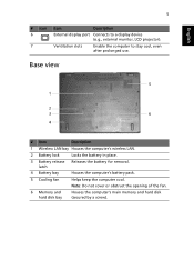
.... 3 Battery release Releases the battery for removal. latch 4 Battery bay Houses the computer's battery pack. 5 Cooling fan Helps keep the computer cool. Note: Do not cover or obstruct the opening of the fan. 6 Memory and hard disk bay Houses the computer's main memory and hard disk (secured by a screw). English 5 # Icon...
.... 3 Battery release Releases the battery for removal. latch 4 Battery bay Houses the computer's battery pack. 5 Cooling fan Helps keep the computer cool. Note: Do not cover or obstruct the opening of the fan. 6 Memory and hard disk bay Houses the computer's main memory and hard disk (secured by a screw). English 5 # Icon...


