
Aspire 4310, 4710, 4710Z Service Guide
Page 73
See "Removing the Battery Pack" on page 62. 3. Carefully insert the flat screwdriver between the middle cover and lower case and gently pry up the middle cover. 5. Open the LCD screen all the way to facilitate the easy removal of the cover releases from the power board, then remove the middle cover. Removing the Middle Cover 1. See "Removing the Keyboard" on page 51. 2. Chapter 3 63 Detach the power board cable from the main unit, then turn it over. 6. Continue prying the middle cover until the full length of the middle cover. 4.
See "Removing the Battery Pack" on page 62. 3. Carefully insert the flat screwdriver between the middle cover and lower case and gently pry up the middle cover. 5. Open the LCD screen all the way to facilitate the easy removal of the cover releases from the power board, then remove the middle cover. Removing the Middle Cover 1. See "Removing the Keyboard" on page 51. 2. Chapter 3 63 Detach the power board cable from the main unit, then turn it over. 6. Continue prying the middle cover until the full length of the middle cover. 4.

Aspire 4310, 4710, 4710Z Service Guide
Page 74
... page 63. 4. See "Removing the Middle Cover" on page 53. 3. Color Black Torque 1.6 kgf-cm Removing the LCD Module 1. See "Removing the Keyboard" on page 63. 5. Step 1~3 Size (Quantity) M2 x L4 (3) 5. Disconnect the microphone cable from the power board. Remove the three screws (A) from the mainboard. 64 Chapter 3 See "Removing the Middle...
... page 63. 4. See "Removing the Middle Cover" on page 53. 3. Color Black Torque 1.6 kgf-cm Removing the LCD Module 1. See "Removing the Keyboard" on page 63. 5. Step 1~3 Size (Quantity) M2 x L4 (3) 5. Disconnect the microphone cable from the power board. Remove the three screws (A) from the mainboard. 64 Chapter 3 See "Removing the Middle...

Aspire 4310, 4710, 4710Z Service Guide
Page 75
Disconnect the LCD coaxial cable from the base of the unit. Step 1~2 Size (Quantity) M2.5 x L8 (2) Color Black Torque 4.0 kgf-cm Chapter 3 65 Pull out the antenna cables as shown. 8. Turn the system over and remove the two screws (F) from the mainboard. 7. 6.
Disconnect the LCD coaxial cable from the base of the unit. Step 1~2 Size (Quantity) M2.5 x L8 (2) Color Black Torque 4.0 kgf-cm Chapter 3 65 Pull out the antenna cables as shown. 8. Turn the system over and remove the two screws (F) from the mainboard. 7. 6.

Aspire 4310, 4710, 4710Z Service Guide
Page 76
.... 12. 9. See "Removing the WLAN Board Module" on page 54. 6. Carefully remove the LCD module from the Lower Case 1. Color Black Torque 4.0 kgf-cm NOTE: Make sure the cables are routed well before connecting the cables back to the unit. Separating the Upper Case from the base unit. See "Removing the... DIMM" on page 55. 7. See "Removing the Optical Drive Module" on page 51. 2. Remove the two screws (F) from the left and right hinge of the LCD module. See "Removing ...
.... 12. 9. See "Removing the WLAN Board Module" on page 54. 6. Carefully remove the LCD module from the Lower Case 1. Color Black Torque 4.0 kgf-cm NOTE: Make sure the cables are routed well before connecting the cables back to the unit. Separating the Upper Case from the base unit. See "Removing the... DIMM" on page 55. 7. See "Removing the Optical Drive Module" on page 51. 2. Remove the two screws (F) from the left and right hinge of the LCD module. See "Removing ...

Aspire 4310, 4710, 4710Z Service Guide
Page 84
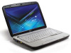
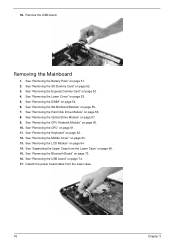
... Board Module" on page 62. 12. See "Removing the Keyboard" on page 55. 7. See "Removing the CPU" on page 64. 14. See "Removing the LCD Module" on page 61. 11. See "Separating the Upper Case from the mainboard. 16. See "Removing the CPU Heatsink Module" on page 54. 6. See "Removing...page 60. 10. See "Removing the Optical Drive Module" on page 52. 3. See "Removing the SD Dummy Card" on page 57. 9. 15. Disconnect the Bluetooth cable from the Lower Case" on page 63. 13. Carefully detach the Bluetooth board from the lower case. See "Removing the Battery Pack" on page 56...
... Board Module" on page 62. 12. See "Removing the Keyboard" on page 55. 7. See "Removing the CPU" on page 64. 14. See "Removing the LCD Module" on page 61. 11. See "Separating the Upper Case from the mainboard. 16. See "Removing the CPU Heatsink Module" on page 54. 6. See "Removing...page 60. 10. See "Removing the Optical Drive Module" on page 52. 3. See "Removing the SD Dummy Card" on page 57. 9. 15. Disconnect the Bluetooth cable from the Lower Case" on page 63. 13. Carefully detach the Bluetooth board from the lower case. See "Removing the Battery Pack" on page 56...
Aspire 4310, 4710, 4710Z Service Guide
Page 86
...page 55. 7. See "Removing the WLAN Board Module" on page 74. 17. See "Removing the Optical Drive Module" on page 64. 14. See "Removing the LCD Module" on page 57. 9. See "Removing the DIMM" on page 66. 15. See "Separating the Upper Case from the lower case. 76 Chapter 3 Detach the... power board cable from the Lower Case" on page 54. 6. See "Removing the CPU Heatsink Module" on page 52. 3. See "Removing the SD Dummy Card" on page 60...
...page 55. 7. See "Removing the WLAN Board Module" on page 74. 17. See "Removing the Optical Drive Module" on page 64. 14. See "Removing the LCD Module" on page 57. 9. See "Removing the DIMM" on page 66. 15. See "Separating the Upper Case from the lower case. 76 Chapter 3 Detach the... power board cable from the Lower Case" on page 54. 6. See "Removing the CPU Heatsink Module" on page 52. 3. See "Removing the SD Dummy Card" on page 60...
Aspire 4310, 4710, 4710Z Service Guide
Page 89
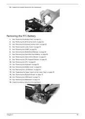
... the Optical Drive Module" on page 61. 11. See "Removing the CPU" on page 57. 9. See "Removing the Mainboard" on page 52. 4. Detach the battery cable from the mainboard. See "Removing the Express Dummy Card" on page 76. 18. See "Removing the CPU Heatsink Module" on page 73. 16. See "Removing... "Removing the DIMM" on page 51. 2. See "Removing the Middle Cover" on page 64. 14. Detach the modem board from the mainboard. See "Removing the LCD Module" on page 63. 13. See "Removing the WLAN Board Module" on page 66. 15. See "Separating the Upper Case from the Lower Case" on...
... the Optical Drive Module" on page 61. 11. See "Removing the CPU" on page 57. 9. See "Removing the Mainboard" on page 52. 4. Detach the battery cable from the mainboard. See "Removing the Express Dummy Card" on page 76. 18. See "Removing the CPU Heatsink Module" on page 73. 16. See "Removing... "Removing the DIMM" on page 51. 2. See "Removing the Middle Cover" on page 64. 14. Detach the modem board from the mainboard. See "Removing the LCD Module" on page 63. 13. See "Removing the WLAN Board Module" on page 66. 15. See "Separating the Upper Case from the Lower Case" on...

Aspire 4310, 4710, 4710Z Service Guide
Page 91
LCD Module Disassembly Process LCD Module Disassembly Flowchart LCD MODULE DISASSEMBLY LCD MODULE Gx6 LCD BEZEL Gx2 INVERTER BOARD LCD FPC CABLE LCD ASSEMBLY Gx2 Hx2 LEFT LCD BRACKET Hx2 RIGHT LCD BRACKET Gx1 LEFT HINGE Gx1 RIGHT HINGE MICROPHONE MAIN ANTENNA AUXILIARY ANTENNA Main Screw List Item G H LCD BACK PANEL Screw M2.5 x L6 M2 x L3 Part No. 86.00E33.736 86.00C07.220 Chapter 3 81
LCD Module Disassembly Process LCD Module Disassembly Flowchart LCD MODULE DISASSEMBLY LCD MODULE Gx6 LCD BEZEL Gx2 INVERTER BOARD LCD FPC CABLE LCD ASSEMBLY Gx2 Hx2 LEFT LCD BRACKET Hx2 RIGHT LCD BRACKET Gx1 LEFT HINGE Gx1 RIGHT HINGE MICROPHONE MAIN ANTENNA AUXILIARY ANTENNA Main Screw List Item G H LCD BACK PANEL Screw M2.5 x L6 M2 x L3 Part No. 86.00E33.736 86.00C07.220 Chapter 3 81

Aspire 4310, 4710, 4710Z Service Guide
Page 94
... 6. See "Removing the Hard Disk Drive Module" on page 62. 10. See "Removing the Optical Drive Module" on page 82. 13. See "Removing the LCD Bezel" on page 57. 7. See "Removing the Battery Pack" on page 83. 84 Chapter 3 See "Removing the Inverter Board" on page 51. 2. Disconnect... the inverter board cable from its connector. 16. See "Removing the Lower Cover" on page 60. 8. See "Removing the CPU Heatsink Module" on page 53. 3. See "Removing the CPU" on page 63. 11. See "Removing the Middle Cover" on page 61. 9. 14. See "Removing the LCD Module" on page...
... 6. See "Removing the Hard Disk Drive Module" on page 62. 10. See "Removing the Optical Drive Module" on page 82. 13. See "Removing the LCD Bezel" on page 57. 7. See "Removing the Battery Pack" on page 83. 84 Chapter 3 See "Removing the Inverter Board" on page 51. 2. Disconnect... the inverter board cable from its connector. 16. See "Removing the Lower Cover" on page 60. 8. See "Removing the CPU Heatsink Module" on page 53. 3. See "Removing the CPU" on page 63. 11. See "Removing the Middle Cover" on page 61. 9. 14. See "Removing the LCD Module" on page...

Aspire 4310, 4710, 4710Z Service Guide
Page 95
14. Remove the two screws (G) securing the left and right LCD brackets to the back panel. Torque 2.5 kgf-cm 16. Step 1~2 Size (Quantity) M2.5 x L6 (2) Color Silver 15. Detach the acetic tapes holding the cables to the LCD back cover. Chapter 3 85 Detach the LCD with the brackets from the back cover, then turn it over.
14. Remove the two screws (G) securing the left and right LCD brackets to the back panel. Torque 2.5 kgf-cm 16. Step 1~2 Size (Quantity) M2.5 x L6 (2) Color Silver 15. Detach the acetic tapes holding the cables to the LCD back cover. Chapter 3 85 Detach the LCD with the brackets from the back cover, then turn it over.

Aspire 4310, 4710, 4710Z Service Guide
Page 96
17. Detach the acetic tape securing the FPC connector. 19. Detach the acetic tapes holding the FPC cable to the edge of the LCD panel. 18. Disconnect the FPC cable from the LCD panel. 86 Chapter 3
17. Detach the acetic tape securing the FPC connector. 19. Detach the acetic tapes holding the FPC cable to the edge of the LCD panel. 18. Disconnect the FPC cable from the LCD panel. 86 Chapter 3

Aspire 4310, 4710, 4710Z Service Guide
Page 100
13. Carefully remove the microphone cable from underneath the adhesive aluminum foil. 17. Remove the microphone. 90 Chapter 3 See "Removing the Antennas" on page 83. 14. See "Removing the Inverter Board" on page 88. 16. See "Removing the LCD with Brackets" on page 84. 15.
13. Carefully remove the microphone cable from underneath the adhesive aluminum foil. 17. Remove the microphone. 90 Chapter 3 See "Removing the Antennas" on page 83. 14. See "Removing the Inverter Board" on page 88. 16. See "Removing the LCD with Brackets" on page 84. 15.

Aspire 4310, 4710, 4710Z Service Guide
Page 106
... Setup Utility. T Reconnect the DIMM T Mainboard T Power source (battery pack and power adapter.) See "Power System Check" on LCD during POST. T Reconnect the LCD connector T Hard disk drive T LCD cable T LCD inverter board T LCD T Mainboard T Reconnect the LCD connectors. T Mainboard T Reconnect the hard disk drive connector. T RTC battery T Run the BIOS Setup Utility to check if the...
... Setup Utility. T Reconnect the DIMM T Mainboard T Power source (battery pack and power adapter.) See "Power System Check" on LCD during POST. T Reconnect the LCD connector T Hard disk drive T LCD cable T LCD inverter board T LCD T Mainboard T Reconnect the LCD connectors. T Mainboard T Reconnect the hard disk drive connector. T RTC battery T Run the BIOS Setup Utility to check if the...

Aspire 4310, 4710, 4710Z Service Guide
Page 107
... LED board T Mainboard No beep, power-on indicator turns on page 93. See "Power System Check" on and LCD is blank. T LCD inverter ID T LCD cable T LCD inverter board T LCD T Mainboard No beep, power-on indicator turns on page 93. T Power source (battery pack and power adapter). ...and correctly. T Speaker T Mainboard Chapter 4 97 T Mainboard No beep during POST. T Reconnect the LCD connector T Hard disk drive T LCD inverter ID T LCD cable T LCD Inverter board T LCD T Mainboard No beep, power-on indicator turns on an external CRT. Error Message List Error Messages Check...
... LED board T Mainboard No beep, power-on indicator turns on page 93. See "Power System Check" on and LCD is blank. T LCD inverter ID T LCD cable T LCD inverter board T LCD T Mainboard No beep, power-on indicator turns on page 93. T Power source (battery pack and power adapter). ...and correctly. T Speaker T Mainboard Chapter 4 97 T Mainboard No beep during POST. T Reconnect the LCD connector T Hard disk drive T LCD inverter ID T LCD cable T LCD Inverter board T LCD T Mainboard No beep, power-on indicator turns on an external CRT. Error Message List Error Messages Check...

Aspire 4310, 4710, 4710Z Service Guide
Page 112
...drive & battery connection board T Mainboard 102 Chapter 4 T LCD inverter ID T LCD cable T LCD inverter board T LCD T Mainboard T Reconnect the LCD connector T LCD inverter ID T LCD cable T LCD inverter board T LCD T Mainboard T LCD inverter ID T LCD inverter board T LCD cable T LCD T Mainboard Indicator-Related Symptoms Symptom / Error Indicator incorrectly remains ... Setup Utility, then reboot system. Check or do the following in characters Abnormal screen Wrong color displayed LCD has extra horizontal or vertical lines displayed. T Battery pack T Power adapter T Hard disk drive &...
...drive & battery connection board T Mainboard 102 Chapter 4 T LCD inverter ID T LCD cable T LCD inverter board T LCD T Mainboard T Reconnect the LCD connector T LCD inverter ID T LCD cable T LCD inverter board T LCD T Mainboard T LCD inverter ID T LCD inverter board T LCD cable T LCD T Mainboard Indicator-Related Symptoms Symptom / Error Indicator incorrectly remains ... Setup Utility, then reboot system. Check or do the following in characters Abnormal screen Wrong color displayed LCD has extra horizontal or vertical lines displayed. T Battery pack T Power adapter T Hard disk drive &...

Aspire 4310, 4710, 4710Z Service Guide
Page 114
...following in BIOS Setup Utility, then reboot system. USB does not work . T Hard disk connection board T Hard disk drive T Mainboard T See "Save to LCD or CRT T Mainboard T Mainboard T Run printer self-test. T Press Fn+F5 to switch to Disk (S4)" on page 44. Battery fuel gauge in... pack T Mainboard T Reconnect hard disk/CD-ROM drives. T Reconnect hard disk/CD-ROM/diskette drives. T Keyboard T Mainboard T Reconnect touchpad cable. T Mainboard T Remove battery pack and let it cool for 2 hours. T Hard disk connection board T Mainboard Peripheral-Related Symptoms Symptom / ...
...following in BIOS Setup Utility, then reboot system. USB does not work . T Hard disk connection board T Hard disk drive T Mainboard T See "Save to LCD or CRT T Mainboard T Mainboard T Run printer self-test. T Press Fn+F5 to switch to Disk (S4)" on page 44. Battery fuel gauge in... pack T Mainboard T Reconnect hard disk/CD-ROM drives. T Reconnect hard disk/CD-ROM/diskette drives. T Keyboard T Mainboard T Reconnect touchpad cable. T Mainboard T Remove battery pack and let it cool for 2 hours. T Hard disk connection board T Mainboard Peripheral-Related Symptoms Symptom / ...

Aspire 4310, 4710, 4710Z Service Guide
Page 120
Board Layout Top View # Item # Item 1 LCD connector 6 Power board cable connector 2 Internal microphone cable connector 7 USB board cable connector 3 Speaker cable connector 8 ExpressCard/54 slot 4 Keyboard cable connector 9 ICH8-M chipset (south bridge) 5 Touchpad cable connector 10 Launch board cable connector 110 Chapter 5
Board Layout Top View # Item # Item 1 LCD connector 6 Power board cable connector 2 Internal microphone cable connector 7 USB board cable connector 3 Speaker cable connector 8 ExpressCard/54 slot 4 Keyboard cable connector 9 ICH8-M chipset (south bridge) 5 Touchpad cable connector 10 Launch board cable connector 110 Chapter 5

Aspire 4310, 4710, 4710Z Service Guide
Page 133
LCD WXGA HL C.A. LCD WXGA MEC Acer Part No. 9J.N5982.V0C 9J.N5982.V0D 9J.N5982.V0E 9J.N5982.V0F 9J.....TK501.001 19.21072.013 19.21066.034 50.4T901.001 50.4T901.011 Chapter 4 123 Category Keyboard (cont.) LCD module Part Name Keyboard 89 key Darfon NSKH3V0C CZ Czech Keyboard 89 key Darfon NSKH3V0D DM Danish Keyboard 89 key Darfon... Inverter board 17" FOXCONN T62I240.02 V.00 Inverter board 17" YEC YNVW06S Inverter board 17" Darfon VK.21189.406 LCD cable 14.1: WXGA HL LCD cable 14.1: WXGA MEC LCD 14.1" camera 0.3M PC+ABS Inverter 17" T62I240.02 V.00 Inverter 17" YNV-W06S Inverter 17" ROHS VK....
LCD WXGA HL C.A. LCD WXGA MEC Acer Part No. 9J.N5982.V0C 9J.N5982.V0D 9J.N5982.V0E 9J.N5982.V0F 9J.....TK501.001 19.21072.013 19.21066.034 50.4T901.001 50.4T901.011 Chapter 4 123 Category Keyboard (cont.) LCD module Part Name Keyboard 89 key Darfon NSKH3V0C CZ Czech Keyboard 89 key Darfon NSKH3V0D DM Danish Keyboard 89 key Darfon... Inverter board 17" FOXCONN T62I240.02 V.00 Inverter board 17" YEC YNVW06S Inverter board 17" Darfon VK.21189.406 LCD cable 14.1: WXGA HL LCD cable 14.1: WXGA MEC LCD 14.1" camera 0.3M PC+ABS Inverter 17" T62I240.02 V.00 Inverter 17" YNV-W06S Inverter 17" ROHS VK....

Aspire 4310, 4710, 4710Z Service Guide
Page 142
LCD WXGA MEC Acer Part No. 9J.N5982.V0C 9J.N5982.V0D 9J.N5982.V0E 9J.N5982.V0F 9J.N5982.V0G...19.TK501.001 19.21072.013 19.21066.034 50.4T901.001 50.4T901.011 132 Chapter 4 Category Keyboard (cont.) LCD module Part Name Keyboard 89 key Darfon NSKH3V0C CZ Czech Keyboard 89 key Darfon NSKH3V0D DM Danish Keyboard 89 key Darfon ...Inverter board 17" FOXCONN T62I240.02 V.00 Inverter board 17" YEC YNVW06 Inverter board 17" Darfon VK.21189.406 LCD cable 14.1: WXGA HL LCD cable 14.1: WXGA MEC LCD 14.1" camera 0.3M PC+ABS Inverter 17" T62I240.02 V.00 Inverter 17" YNV-W06 Inverter 17" ROHS VK....
LCD WXGA MEC Acer Part No. 9J.N5982.V0C 9J.N5982.V0D 9J.N5982.V0E 9J.N5982.V0F 9J.N5982.V0G...19.TK501.001 19.21072.013 19.21066.034 50.4T901.001 50.4T901.011 132 Chapter 4 Category Keyboard (cont.) LCD module Part Name Keyboard 89 key Darfon NSKH3V0C CZ Czech Keyboard 89 key Darfon NSKH3V0D DM Danish Keyboard 89 key Darfon ...Inverter board 17" FOXCONN T62I240.02 V.00 Inverter board 17" YEC YNVW06 Inverter board 17" Darfon VK.21189.406 LCD cable 14.1: WXGA HL LCD cable 14.1: WXGA MEC LCD 14.1" camera 0.3M PC+ABS Inverter 17" T62I240.02 V.00 Inverter 17" YNV-W06 Inverter 17" ROHS VK....

Aspire 4310, 4710, 4710Z Service Guide
Page 151
Category Keyboard (cont.) LCD module Part Name Keyboard 89 key Darfon NSKH3V0C CZ Czech Keyboard 89 key Darfon NSKH3V0D DM Danish Keyboard 89 key Darfon NSKH3V0E IT Italian Keyboard ... 17" YEC YNVW06S Inverter board 17" Darfon VK.21189.406 LCD cable 14.1: WXGA HL LCD cable 14.1: WXGA MEC LCD 14.1" camera 0.3M PC+ABS Inverter 17" T62I240.02 V.00 Inverter 17" YNV-W06S Inverter 17" ROHS VK.21189.406 C.A. LCD WXGA HL C.A. LCD WXGA MEC Acer Part No. 9J.N5982.V0C 9J.N5982.V0D 9J.N5982...
Category Keyboard (cont.) LCD module Part Name Keyboard 89 key Darfon NSKH3V0C CZ Czech Keyboard 89 key Darfon NSKH3V0D DM Danish Keyboard 89 key Darfon NSKH3V0E IT Italian Keyboard ... 17" YEC YNVW06S Inverter board 17" Darfon VK.21189.406 LCD cable 14.1: WXGA HL LCD cable 14.1: WXGA MEC LCD 14.1" camera 0.3M PC+ABS Inverter 17" T62I240.02 V.00 Inverter 17" YNV-W06S Inverter 17" ROHS VK.21189.406 C.A. LCD WXGA HL C.A. LCD WXGA MEC Acer Part No. 9J.N5982.V0C 9J.N5982.V0D 9J.N5982...


