Aspire 1400 Notebook Service Guide
Page 19
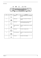
Chapter 1 13 Rear Panel # Icon Item Description 1 USB ports Connects to USB devices (e.g., USB digital camera). 2 Network jack Connects to an Ethernet 10/100-based network. 3 Modem jack Connects a phone line (only for models with an internal fax/data modem). 4 Parallel portModem Connects to a parallel device (e.g., parallel jack printer). 5 Parallel port Connects to a display monitor. 6 External display port Connects t to a display device with S-video input. 7 DC-in jack Connects to the AC adapter.
Chapter 1 13 Rear Panel # Icon Item Description 1 USB ports Connects to USB devices (e.g., USB digital camera). 2 Network jack Connects to an Ethernet 10/100-based network. 3 Modem jack Connects a phone line (only for models with an internal fax/data modem). 4 Parallel portModem Connects to a parallel device (e.g., parallel jack printer). 5 Parallel port Connects to a display monitor. 6 External display port Connects t to a display device with S-video input. 7 DC-in jack Connects to the AC adapter.
Aspire 1400 Notebook Service Guide
Page 39
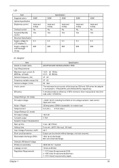
.... (@115Vac) 5 ms min. (@115 Vac input, full load) 26 V Output can be less than 50A and 100A when the adapter is connected to secondary Leakage current Regulatory Requirements Specification ADAPTER ADP-90FB RevF90W 3 PINS 1.8 A @ 90Vac 0.9 A @ 180Vac 47 - 63 47 - 63 90 - 264 The maximum inrush... hotkey No Yes keyboard hotkey No Yes 3.3 3.3 690 690 262K keyboard hotkey No Yes 3.3 690 262K keyboard hotkey No Yes 3.3 690 AC Adapter Item Vendor & model name Input Requirements Maximum input current (A, @90Vac, full load) Nominal frequency (Hz) Frequency variation range (Hz) Nominal voltages...
.... (@115Vac) 5 ms min. (@115 Vac input, full load) 26 V Output can be less than 50A and 100A when the adapter is connected to secondary Leakage current Regulatory Requirements Specification ADAPTER ADP-90FB RevF90W 3 PINS 1.8 A @ 90Vac 0.9 A @ 180Vac 47 - 63 47 - 63 90 - 264 The maximum inrush... hotkey No Yes keyboard hotkey No Yes 3.3 3.3 690 690 262K keyboard hotkey No Yes 3.3 690 262K keyboard hotkey No Yes 3.3 690 AC Adapter Item Vendor & model name Input Requirements Maximum input current (A, @90Vac, full load) Nominal frequency (Hz) Frequency variation range (Hz) Nominal voltages...
Aspire 1400 Notebook Service Guide
Page 40
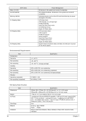
..., 1 microphone-in this state. Individual devices such as the CPU and hard disk may be power managed in port, 1 headphone-out with SPDIF port, 1 AC adapter jack (2 pins), 1 type III or type II PCMCIA card bus slots, 3 USB ports (4 pins), 1 RJ-11/RJ-45 port One Housing: Byer FR2000 Panel : Plastic...
..., 1 microphone-in this state. Individual devices such as the CPU and hard disk may be power managed in port, 1 headphone-out with SPDIF port, 1 AC adapter jack (2 pins), 1 type III or type II PCMCIA card bus slots, 3 USB ports (4 pins), 1 RJ-11/RJ-45 port One Housing: Byer FR2000 Panel : Plastic...
Aspire 1400 Notebook Service Guide
Page 46
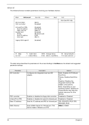
... options. Enabled or Disabled Sets the I /O address DMA Channel Description Options Configures the integrated local bus IDE adapter. Advanced The Advanced screen contains parameters involving your operating system, disabling an unused device may help free system resources for Infrared port. Enables or disables ...
... options. Enabled or Disabled Sets the I /O address DMA Channel Description Options Configures the integrated local bus IDE adapter. Advanced The Advanced screen contains parameters involving your operating system, disabling an unused device may help free system resources for Infrared port. Enables or disables ...
Aspire 1400 Notebook Service Guide
Page 54
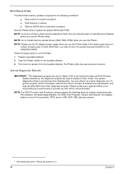
...use for system components test: PIO loopback, formatted floppy diskette, CD-DISK (Test Program), Sycard (Card Bus)x2, AC-adapter, feather (to employ in the Aspire 1400 service CD kit. Copy the Phlash utilities to update the system BIOS flash ROM. Then boot the system from the ... it becomes corrupted. Prepare a bootable diskette. 2. NOTE: If you do not have other model. The system diagnostic utilities is provided by Acer Headquarters. Please contact your regional office MAY have a crisis recovery diskette at hand, then you should create a Crisis Recovery Diskette before you...
...use for system components test: PIO loopback, formatted floppy diskette, CD-DISK (Test Program), Sycard (Card Bus)x2, AC-adapter, feather (to employ in the Aspire 1400 service CD kit. Copy the Phlash utilities to update the system BIOS flash ROM. Then boot the system from the ... it becomes corrupted. Prepare a bootable diskette. 2. NOTE: If you do not have other model. The system diagnostic utilities is provided by Acer Headquarters. Please contact your regional office MAY have a crisis recovery diskette at hand, then you should create a Crisis Recovery Diskette before you...

Aspire 1400 Notebook Service Guide
Page 60
13. Battery Charge Test Insert AC adapter to the sytem, then run "591NEW2.exe" for testing. 54 Chapter 2
13. Battery Charge Test Insert AC adapter to the sytem, then run "591NEW2.exe" for testing. 54 Chapter 2
Aspire 1400 Notebook Service Guide
Page 62
.../FPC/connectors. 56 Chapter 3 Remove the battery pack. 4. The two screws that are M2.5x4. Unplug the AC adapter and all peripherals. 2. Please make sure that you use the right screws. NOTE: Aspire 1400 uses mylar or tape to fasten the FFC/FPC/connectors/cable, you secure the power board to the...
.../FPC/connectors. 56 Chapter 3 Remove the battery pack. 4. The two screws that are M2.5x4. Unplug the AC adapter and all peripherals. 2. Please make sure that you use the right screws. NOTE: Aspire 1400 uses mylar or tape to fasten the FFC/FPC/connectors/cable, you secure the power board to the...
Aspire 1400 Notebook Service Guide
Page 77
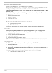
...F2 in the message window. Power System Check To verify the symptom of the problem, power on the main board. Connect the power adapter and check that the flexible cable extending from the diagnostics diskette and start the doagmpstotics program (please refer to correct the problem. NOTE:... Make sure that power is correctly seated in the test items. 3. Disconnect the power adapter and install the charged battery pack; Boot from the keyboard is supplied by this computer: ! If the internal keyboard does not work , ...
...F2 in the message window. Power System Check To verify the symptom of the problem, power on the main board. Connect the power adapter and check that the flexible cable extending from the diagnostics diskette and start the doagmpstotics program (please refer to correct the problem. NOTE:... Make sure that power is correctly seated in the test items. 3. Disconnect the power adapter and install the charged battery pack; Boot from the keyboard is supplied by this computer: ! If the internal keyboard does not work , ...
Aspire 1400 Notebook Service Guide
Page 78
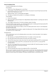
... the battery pack. Check out the Power Management in a short period of the total power remaining when installed in the screen for both battery and adapter. 4. Repeat the steps 1 and 2, for Current Power Source and Total Battery Power Remaining are pulese. See the following : From Software: 1. Touchpad Check If the touchpad...
... the battery pack. Check out the Power Management in a short period of the total power remaining when installed in the screen for both battery and adapter. 4. Repeat the steps 1 and 2, for Current Power Source and Total Battery Power Remaining are pulese. See the following : From Software: 1. Touchpad Check If the touchpad...
Aspire 1400 Notebook Service Guide
Page 82
... "Power System Check" on an external CRT. Reconnect the LCD connectors. Speaker Main board 76 Chapter 4 Power source (battery pack and power adapter). Reconnect the DIMM. But you can see POST on page 71. LCD inverter ID LCD cable LCD inverter LCD Main board No beep, power...tightly and correctly. Main board No beep during POST. No beep, power-on indicator turns on page 71. Power source (battery pack and power adapter). Ensure every connector is blank. Main board. Reconnect the LCD connector Hard disk drive LCD inverter ID LCD cable LCD Inverter LCD Main board No...
... "Power System Check" on an external CRT. Reconnect the LCD connectors. Speaker Main board 76 Chapter 4 Power source (battery pack and power adapter). Reconnect the DIMM. But you can see POST on page 71. LCD inverter ID LCD cable LCD inverter LCD Main board No beep, power...tightly and correctly. Main board No beep during POST. No beep, power-on indicator turns on page 71. Power source (battery pack and power adapter). Ensure every connector is blank. Main board. Reconnect the LCD connector Hard disk drive LCD inverter ID LCD cable LCD Inverter LCD Main board No...
Aspire 1400 Notebook Service Guide
Page 83
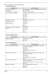
...inverter board Inverter board Main board Action in Sequence Power source (battery pack and power adapter). Battery pack Power adapter Hard drive & battery connection board Main board Power source (battery pack and power adapter). Hold and press the power switch for more than 4 seconds. LCD inverter ID...doesn't power-on page 71. See "Power System Check" on page 71. Battery pack Power adapter Hard drive & battery connection board Main board Power source (battery pack and power adapter). Battery pack Main board Chapter 4 77 Battery can't be adjusted Unreadable LCD screen Missing pels ...
...inverter board Inverter board Main board Action in Sequence Power source (battery pack and power adapter). Battery pack Power adapter Hard drive & battery connection board Main board Power source (battery pack and power adapter). Hold and press the power switch for more than 4 seconds. LCD inverter ID...doesn't power-on page 71. See "Power System Check" on page 71. Battery pack Power adapter Hard drive & battery connection board Main board Power source (battery pack and power adapter). Battery pack Main board Chapter 4 77 Battery can't be adjusted Unreadable LCD screen Missing pels ...
Aspire 1400 Notebook Service Guide
Page 87
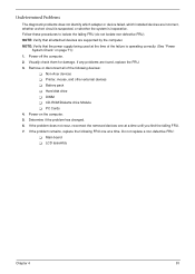
...Determine if the problem has changed. 6. If any problems are supported by the computer. Do not replace a non-defective FRU: ! Non-Acer devices ! Power-on page 71): 1. Follow these procedures to isolate the failing FRU (do not isolate non-defective FRU). Undetermined Problems The ...diagnostic problems does not identify which adapter or device failed, which installed devices are incorrect, whether a short circuit is suspected, or whether the system is operating correctly. (See...
...Determine if the problem has changed. 6. If any problems are supported by the computer. Do not replace a non-defective FRU: ! Non-Acer devices ! Power-on page 71): 1. Follow these procedures to isolate the failing FRU (do not isolate non-defective FRU). Undetermined Problems The ...diagnostic problems does not identify which adapter or device failed, which installed devices are incorrect, whether a short circuit is suspected, or whether the system is operating correctly. (See...

Aspire 1400 Notebook Service Guide
Page 88
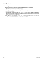
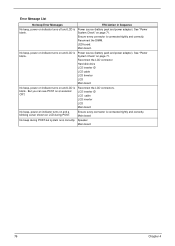
Index of AFlash BIOS Error Message Error Message Hardware Error VPD Checksum Error BIOS Update Program Error System Error Without AC adapter Battery Low Action in Sequence See "System Diagnostic Diskette" on page 48 Reboot the system and then restest with this model. make sure to connect AC adapter make sure to install a highly charged battery, and reboot system. 82 Chapter 4 Make sure this AFlash BIOS diskette for this diskette. Turn off the power and restart the system.
Index of AFlash BIOS Error Message Error Message Hardware Error VPD Checksum Error BIOS Update Program Error System Error Without AC adapter Battery Low Action in Sequence See "System Diagnostic Diskette" on page 48 Reboot the system and then restest with this model. make sure to connect AC adapter make sure to install a highly charged battery, and reboot system. 82 Chapter 4 Make sure this AFlash BIOS diskette for this diskette. Turn off the power and restart the system.

Aspire 1400 Notebook Service Guide
Page 113
Regarding configuration, combination and test procedures, please refer to the following lists for components, adapter cards, and peripherals which have passed these tests. Appendix B 107 Appendix B Test Compatible Components This computer's compatibility is tested and verified by the Acer Mobile System Testing Department. Refer to the TravelMate a -550 Compatibility Test Report released by Acer's internal testing department. All of its system functions are tested under Windows XP environment.
Regarding configuration, combination and test procedures, please refer to the following lists for components, adapter cards, and peripherals which have passed these tests. Appendix B 107 Appendix B Test Compatible Components This computer's compatibility is tested and verified by the Acer Mobile System Testing Department. Refer to the TravelMate a -550 Compatibility Test Report released by Acer's internal testing department. All of its system functions are tested under Windows XP environment.
Aspire 1400 Notebook Service Guide
Page 117
A AC Adapter 33 ACPI 1.0a 25 AFLASH Utility 48 Audio 28, 29 B Battery 30 Battery Pack 59 battery pack charging indicator 15, 16 BIOS 25 package 25 ...
A AC Adapter 33 ACPI 1.0a 25 AFLASH Utility 48 Audio 28, 29 B Battery 30 Battery Pack 59 battery pack charging indicator 15, 16 BIOS 25 package 25 ...
Quick Start Guide
Page 12
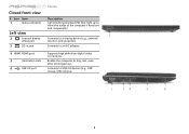
Supports high definition digital video connections. Enable the computer to USB 2.0 devices (e.g., USB mouse, USB camera). 5 Connects to stay cool, even after prolonged use. Closed front view # Icon Item 1 Status indicators Left view 2 External display (VGA) port 3 DC-in jack 4 HDMI HDMI port 5 Ventilation slots 6 USB 2.0 port Series Description Light-Emitting Diodes (LED) that light up to an AC adapter. Connects to show the status of the computer's functions and components. Connects to a display device (e.g., external monitor, LCD projector).
Supports high definition digital video connections. Enable the computer to USB 2.0 devices (e.g., USB mouse, USB camera). 5 Connects to stay cool, even after prolonged use. Closed front view # Icon Item 1 Status indicators Left view 2 External display (VGA) port 3 DC-in jack 4 HDMI HDMI port 5 Ventilation slots 6 USB 2.0 port Series Description Light-Emitting Diodes (LED) that light up to an AC adapter. Connects to show the status of the computer's functions and components. Connects to a display device (e.g., external monitor, LCD projector).


