
Aspire 1360 - 1520 Service Guide
Page 7
... Middle Cover 54 Removing the Launch Board 54 Removing the LCD Module 55 Disassembling the LCD Module 57 Removing the LCD Bezel 57 Removing the Inverter Board (15" LCD 57 Removing the 15" TFT LCD 58 Removing the LCD Brackets 59 Removing the LCD Coaxial Cable 59 Removing the LCD Hinges 60 Disassembling the Main Unit 61 Removing the...
... Middle Cover 54 Removing the Launch Board 54 Removing the LCD Module 55 Disassembling the LCD Module 57 Removing the LCD Bezel 57 Removing the Inverter Board (15" LCD 57 Removing the 15" TFT LCD 58 Removing the LCD Brackets 59 Removing the LCD Coaxial Cable 59 Removing the LCD Hinges 60 Disassembling the Main Unit 61 Removing the...

Aspire 1360 - 1520 Service Guide
Page 13
Board Layout Top View 1 Line-in Port 2 Line-out Port 3 RJ45+RJ11 4 LCD Inverter Cable Connector 5 USB Port 6 USB Port 7 USB Port 8 USB Port 9 VGA Port 10 S-Video Port 11 LCD Coaxial Cable Connector 12 Parallel Port 13 DC-in Port 14 LCD Lid Switch 15 CPU Socket 16 North Bridge 17 Fan Connector 18 Note...: There is no 18 on this main board. 19 Touchpad Cable Connector 20 HDD Connector 21 Keyboard Connector 22 Speaker...
Board Layout Top View 1 Line-in Port 2 Line-out Port 3 RJ45+RJ11 4 LCD Inverter Cable Connector 5 USB Port 6 USB Port 7 USB Port 8 USB Port 9 VGA Port 10 S-Video Port 11 LCD Coaxial Cable Connector 12 Parallel Port 13 DC-in Port 14 LCD Lid Switch 15 CPU Socket 16 North Bridge 17 Fan Connector 18 Note...: There is no 18 on this main board. 19 Touchpad Cable Connector 20 HDD Connector 21 Keyboard Connector 22 Speaker...

Aspire 1360 - 1520 Service Guide
Page 57
...order. Start Battery HDD Module G*2 HDD HDD Holder *2 DIMM Cover Memory *2 Modem Cover Hinge Caps Wireless LAN Board D*2 Modem Board J*2 Middle Cover RTC Battery Keyboard F*6 LCD Module *2 Launch Board Second Fan J*3 Bracket Lower Case Assembly J*2 FDD Module J*5 F*10 D*4 Upper Case Assembly D*4 Wireless LAN Antenna Touchpad Cover J*3 Second Fan *4 ... CPU Heatsink Plate J*7 VGA Thermal Plate Touchpad Button Pad D*2 ODD Bracket ODD *4 Main Board Touchpad Touchpad Scroll Key D*2 DC Board D*4 PCMCIA Slot Touchpad Cable Upper Case *2 Speaker Set Chapter 3 48
...order. Start Battery HDD Module G*2 HDD HDD Holder *2 DIMM Cover Memory *2 Modem Cover Hinge Caps Wireless LAN Board D*2 Modem Board J*2 Middle Cover RTC Battery Keyboard F*6 LCD Module *2 Launch Board Second Fan J*3 Bracket Lower Case Assembly J*2 FDD Module J*5 F*10 D*4 Upper Case Assembly D*4 Wireless LAN Antenna Touchpad Cover J*3 Second Fan *4 ... CPU Heatsink Plate J*7 VGA Thermal Plate Touchpad Button Pad D*2 ODD Bracket ODD *4 Main Board Touchpad Touchpad Scroll Key D*2 DC Board D*4 PCMCIA Slot Touchpad Cable Upper Case *2 Speaker Set Chapter 3 48

Aspire 1360 - 1520 Service Guide
Page 58
LCD Module 4 LCD Cushions E*4 LCD Bezel L*1 Inverter L*4 LCD LCD Panel LCD Coaxial Cable H*8 for 14.1" H*6 for 15.0" LCD Brackets Screw List Item A B C D E F G H I J Description SCREW MAC FLAT M2.5*L4 NI NYLOK (86.00123.630) SCREW M2.0*L10 NYLOK(86.9A352.100) SCREW M2*3 NYLON 1JMCPC420325(86.9A352.3R0) SCREW M2.5X6(86.9A353.6R0) SCREW M3x4 (86.9A524.4R0) SCREW M2X2.0 (86.9A552.2R0) SCREW WAFER NYLOK NI 2ML3 (86.9A552.3R0) SCRW M2*4 WAFER NI (86.9A552.4R0) SCRW M2.5*3 WAFER NI (86.9A553.3R0) SCREW M2.5*4L NI (86.9A553.4R0) 49 Chapter 3
LCD Module 4 LCD Cushions E*4 LCD Bezel L*1 Inverter L*4 LCD LCD Panel LCD Coaxial Cable H*8 for 14.1" H*6 for 15.0" LCD Brackets Screw List Item A B C D E F G H I J Description SCREW MAC FLAT M2.5*L4 NI NYLOK (86.00123.630) SCREW M2.0*L10 NYLOK(86.9A352.100) SCREW M2*3 NYLON 1JMCPC420325(86.9A352.3R0) SCREW M2.5X6(86.9A353.6R0) SCREW M3x4 (86.9A524.4R0) SCREW M2X2.0 (86.9A552.2R0) SCREW WAFER NYLOK NI 2ML3 (86.9A552.3R0) SCRW M2*4 WAFER NI (86.9A552.4R0) SCRW M2.5*3 WAFER NI (86.9A553.3R0) SCREW M2.5*4L NI (86.9A553.4R0) 49 Chapter 3

Aspire 1360 - 1520 Service Guide
Page 63
Removing the Launch Board 1. Remove the screw that secures the middle cover. 4. Detach the middle cover from the machine. 7. Remove the left hinge cap. 5. Chapter 3 54 See "Removing the Battery" on page 50. Disconnect the launch board cable then remove the middle cover off the main unit. . Removing the LCD Module Removing the Middle Cover 1. See "Removing the Battery" on page 50. 2. Then remove the screw holding the middle cover on the other side. 6. To remove the middle cover, first use a plastic flat screwdriver to remove the right hinge cap. 3.
Removing the Launch Board 1. Remove the screw that secures the middle cover. 4. Detach the middle cover from the machine. 7. Remove the left hinge cap. 5. Chapter 3 54 See "Removing the Battery" on page 50. Disconnect the launch board cable then remove the middle cover off the main unit. . Removing the LCD Module Removing the Middle Cover 1. See "Removing the Battery" on page 50. 2. Then remove the screw holding the middle cover on the other side. 6. To remove the middle cover, first use a plastic flat screwdriver to remove the right hinge cap. 3.

Aspire 1360 - 1520 Service Guide
Page 64
Remove the screw that fastens the LCD coaxial cable and disconnect the cable. See "Removing the Battery" on page 54. 4. See "Removing the Launch Board" on page 50. 2. one on the right and the other on the left . 7. Removing the LCD Module 1. See "Removing the Middle Cover" on page 54. 3....then detach the launch board from the main unit. 55 Chapter 3 Then disconnect the LCD inverter cable.Then pull out the wireless antennae from the main unit carefully. 5. 2. Remove the four screws holding the LCD hinge; two on the right and two on the left .Remove the four screws...
Remove the screw that fastens the LCD coaxial cable and disconnect the cable. See "Removing the Battery" on page 54. 4. See "Removing the Launch Board" on page 50. 2. one on the right and the other on the left . 7. Removing the LCD Module 1. See "Removing the Middle Cover" on page 54. 3....then detach the launch board from the main unit. 55 Chapter 3 Then disconnect the LCD inverter cable.Then pull out the wireless antennae from the main unit carefully. 5. 2. Remove the four screws holding the LCD hinge; two on the right and two on the left .Remove the four screws...

Aspire 1360 - 1520 Service Guide
Page 66
...Removing the Inverter Board (15" LCD) 1. See "Removing the Middle Cover" on page 55. 5. See "Removing the Launch Board" on page 54. 3. See "Removing the Middle Cover" on page 54. 4. Disconnect the LCD power cable then disconnect the inverter cable from the LCD module. See "Removing the Launch... Board" on page 57. 6. See "Removing the LCD Bezel" on page 54. 4. See "Removing the Battery" on page 55. 5....
...Removing the Inverter Board (15" LCD) 1. See "Removing the Middle Cover" on page 55. 5. See "Removing the Launch Board" on page 54. 3. See "Removing the Middle Cover" on page 54. 4. Disconnect the LCD power cable then disconnect the inverter cable from the LCD module. See "Removing the Launch... Board" on page 57. 6. See "Removing the LCD Bezel" on page 54. 4. See "Removing the Battery" on page 55. 5....

Aspire 1360 - 1520 Service Guide
Page 67
... See "Removing the Battery" on page 55. 5. See "Removing the LCD Module" on page 50. 2. Removing the 15" TFT LCD 1. See "Removing the LCD Bezel" on page 54. 3. Then take the LCD out of the LCD panel. NOTE: Please arrange the LCD inverter cable well to the LCD panel as the picture below shows when you reassemble the...
... See "Removing the Battery" on page 55. 5. See "Removing the LCD Module" on page 50. 2. Removing the 15" TFT LCD 1. See "Removing the LCD Bezel" on page 54. 3. Then take the LCD out of the LCD panel. NOTE: Please arrange the LCD inverter cable well to the LCD panel as the picture below shows when you reassemble the...

Aspire 1360 - 1520 Service Guide
Page 68
..." on page 54. 3. See "Removing the Inverter Board (15" LCD)" on page 58. 8. See "Removing the 15" TFT LCD" on page 57. 7. Removing the LCD Coaxial Cable 1. See "Removing the LCD Module" on page 57. 6. See "Removing the LCD Bezel" on page 55. 5. See "Removing the Launch Board" on... page 57. 7. See "Removing the Inverter Board (15" LCD)" on page 54. 4. Tear off the mylar fastening the LCD coaxial cable, then disconnect the coaxial cable. 59 Chapter 3 Remove the four screws holding the left bracket.. See "Removing the Middle Cover" on...
..." on page 54. 3. See "Removing the Inverter Board (15" LCD)" on page 58. 8. See "Removing the 15" TFT LCD" on page 57. 7. Removing the LCD Coaxial Cable 1. See "Removing the LCD Module" on page 57. 6. See "Removing the LCD Bezel" on page 55. 5. See "Removing the Launch Board" on... page 57. 7. See "Removing the Inverter Board (15" LCD)" on page 54. 4. Tear off the mylar fastening the LCD coaxial cable, then disconnect the coaxial cable. 59 Chapter 3 Remove the four screws holding the left bracket.. See "Removing the Middle Cover" on...
Aspire 1360 - 1520 Service Guide
Page 74
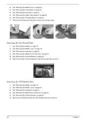
Remove the touchpad scroll key then remove the touchpad cable. See "Removing the Keyboard" on page 54. 3. See "Removing the Middle Cover" on page 61. 4. Remove the seven screws holding the VGA thermal plate then ... the CPU heatsink plate then remove it . See "Removing the Thermal Module" on page 61. 4. See "Removing the Keyboard" on page 62. 6. See "Removing the LCD Module" on page 61. 5. See "Removing the Middle Cover Hook /Fan" on page 55. 4. See "Removing the Middle Cover" on page 54. 3. See "Removing the...
Remove the touchpad scroll key then remove the touchpad cable. See "Removing the Keyboard" on page 54. 3. See "Removing the Middle Cover" on page 61. 4. Remove the seven screws holding the VGA thermal plate then ... the CPU heatsink plate then remove it . See "Removing the Thermal Module" on page 61. 4. See "Removing the Keyboard" on page 62. 6. See "Removing the LCD Module" on page 61. 5. See "Removing the Middle Cover Hook /Fan" on page 55. 4. See "Removing the Middle Cover" on page 54. 3. See "Removing the...

Aspire 1360 - 1520 Service Guide
Page 89
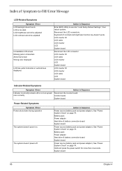
Reconnect the DIMM. Reconnect the LCD connector Hard disk drive LCD inverter ID LCD cable LCD Inverter LCD System board No beep, power-on indicator turns on LCD during POST but system runs correctly. Reconnect the LCD connectors. Speaker System board Chapter 4 80 LCD inverter ID LCD cable LCD inverter LCD System board No beep, power-on indicator turns on and a blinking cursor shown...
Reconnect the DIMM. Reconnect the LCD connector Hard disk drive LCD inverter ID LCD cable LCD Inverter LCD System board No beep, power-on indicator turns on LCD during POST but system runs correctly. Reconnect the LCD connectors. Speaker System board Chapter 4 80 LCD inverter ID LCD cable LCD inverter LCD System board No beep, power-on indicator turns on and a blinking cursor shown...
Aspire 1360 - 1520 Service Guide
Page 94
... board System board Power source (battery pack and power adapter). LCD inverter ID LCD cable LCD inverter LCD System board Reconnect the LCD connector LCD inverter ID LCD cable LCD inverter LCD System board LCD inverter ID LCD inverter LCD cable LCD System board Indicator-Related Symptoms Symptom / Error Action in characters Abnormal screen Wrong color displayed LCD has extra horizontal or vertical lines displayed. See "Power...
... board System board Power source (battery pack and power adapter). LCD inverter ID LCD cable LCD inverter LCD System board Reconnect the LCD connector LCD inverter ID LCD cable LCD inverter LCD System board LCD inverter ID LCD inverter LCD cable LCD System board Indicator-Related Symptoms Symptom / Error Action in characters Abnormal screen Wrong color displayed LCD has extra horizontal or vertical lines displayed. See "Power...
Aspire 1360 - 1520 Service Guide
Page 96
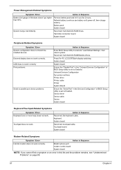
... devices. Touchpad does not work . Refresh battery (continue use battery until power off, then charge battery). Press Fn+F5, LCD/CRT/Both display switching System board System board Ensure the "Parallel Port" in Sequence Enter BIOS Setup Utility to execute "Load ... Configuration" of BIOS Setup Utility is set to Enabled. Printer driver Printer cable Printer System Board Ensure the "Serial Port" in Sequence Reconnect the keyboard cable. Keyboard System board Reconnect touchpad cable. Touchpad board System board Modem-Related Symptoms Symptom / Error Action in Windows...
... devices. Touchpad does not work . Refresh battery (continue use battery until power off, then charge battery). Press Fn+F5, LCD/CRT/Both display switching System board System board Ensure the "Parallel Port" in Sequence Enter BIOS Setup Utility to execute "Load ... Configuration" of BIOS Setup Utility is set to Enabled. Printer driver Printer cable Printer System Board Ensure the "Serial Port" in Sequence Reconnect the keyboard cable. Keyboard System board Reconnect touchpad cable. Touchpad board System board Modem-Related Symptoms Symptom / Error Action in Windows...

Aspire 1360 - 1520 Service Guide
Page 107
... View Chapter 5 1 LIN1 Line-in Port 2 LOUT Line-out Port 3 JK1 RJ45+RJ11 4 INV1 LCD Inverter Cable Connector 5 CN1 USB Port 6 CN2 USB Port 7 CN3 USB Port 8 CN4 USB Port 9 CRT1 VGA Port 10 TV1 S-Video Port 11 LCD1 LCD Coaxial Cable Connector 12 PRT1 Parallel Port 13 DCIN1 DC-in Port 14 CN6... LCD Lid Switch 15 U11 CPU Socket 16 U16 North Bridge 17 FAN1 Fan Connector 18 Note: There is no...
... View Chapter 5 1 LIN1 Line-in Port 2 LOUT Line-out Port 3 JK1 RJ45+RJ11 4 INV1 LCD Inverter Cable Connector 5 CN1 USB Port 6 CN2 USB Port 7 CN3 USB Port 8 CN4 USB Port 9 CRT1 VGA Port 10 TV1 S-Video Port 11 LCD1 LCD Coaxial Cable Connector 12 PRT1 Parallel Port 13 DCIN1 DC-in Port 14 CN6... LCD Lid Switch 15 U11 CPU Socket 16 U16 North Bridge 17 FAN1 Fan Connector 18 Note: There is no...

Aspire 1360 - 1520 Service Guide
Page 117
Aspire 1360 Picture No. Partname And Description LCD BRACKET 15.4" RIGHT Part Number 33.A36V1.001 LCD BRACKET ASSEMBLY 15.1 RIGHT NS LCD BRACKET 15.4" LEFT 33.A36V1.004 33.A36V1.002 LCD BRACKET ASSEMBLY 15.1 LEFT INVERTER CABLE INVERTER CABLE 33.A36V1.003 50.A36V1.004 50.A30V1.001 Chapter 6 LCD COAXIAL CABLE 15.4" LCD COAXIAL CABLE 15.4" 50.A30V1.002 50...
Aspire 1360 Picture No. Partname And Description LCD BRACKET 15.4" RIGHT Part Number 33.A36V1.001 LCD BRACKET ASSEMBLY 15.1 RIGHT NS LCD BRACKET 15.4" LEFT 33.A36V1.004 33.A36V1.002 LCD BRACKET ASSEMBLY 15.1 LEFT INVERTER CABLE INVERTER CABLE 33.A36V1.003 50.A36V1.004 50.A30V1.001 Chapter 6 LCD COAXIAL CABLE 15.4" LCD COAXIAL CABLE 15.4" 50.A30V1.002 50...

Aspire 1360 - 1520 Service Guide
Page 118
... 15" LEFT/RIGHT Part Number 6K.A36V1.001 MAINBOARD W/LAUNCH BOARD CABLE & MODEM CABLE & RTC BATTERY MAINBOARD W/LAUNCH BOARD CABLE & MODEM CABLE & RTC BATTERY & VGA BOARD TBD TBD PCMCIA SLOT TOUCHPAD BUTTON 22.T30V1.001 42.A30V1.005 Memory LCD SCREW CAP LOWER LCD SCREW RUBBER UPPER ICON PLATE LOGO PLATE 47.A16V1.001 47.A16V1...-335C1 SODIMM 512M SAMSUNG M470L6524BT0-CB3 KN.2560B.008 KN.25604.021 KN.25602.012 KN.51202.013 KN.51204.013 KN.5120B.006 Chapter 6 Aspire 1360 Picture Main Board Miscellaneous No.
... 15" LEFT/RIGHT Part Number 6K.A36V1.001 MAINBOARD W/LAUNCH BOARD CABLE & MODEM CABLE & RTC BATTERY MAINBOARD W/LAUNCH BOARD CABLE & MODEM CABLE & RTC BATTERY & VGA BOARD TBD TBD PCMCIA SLOT TOUCHPAD BUTTON 22.T30V1.001 42.A30V1.005 Memory LCD SCREW CAP LOWER LCD SCREW RUBBER UPPER ICON PLATE LOGO PLATE 47.A16V1.001 47.A16V1...-335C1 SODIMM 512M SAMSUNG M470L6524BT0-CB3 KN.2560B.008 KN.25604.021 KN.25602.012 KN.51202.013 KN.51204.013 KN.5120B.006 Chapter 6 Aspire 1360 Picture Main Board Miscellaneous No.


