Aspire X1200 / X3200 Service Guide
Page 7
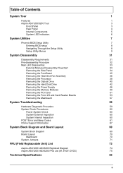
... Removing the Processor 38 Removing the Optical Drive 40 Removing the Hard Disk Drive 42 Removing the Power Supply 46 Removing the Memory Modules 49 Removing the PCI Card 51 Removing the Front I/O and Card Reader Boards 53 Removing the Mainboard 57 System Troubleshooting 59 Hardware Diagnostic Procedure 59 System Check Procedures 60 Power System Check 60 System External Inspection 60 System Internal Inspection 60 POST Error and Beep Codes 61 Online Support Information 67 System Block Diagram and Board Layout 69 System Block Diagram 69 Board Layout...
... Removing the Processor 38 Removing the Optical Drive 40 Removing the Hard Disk Drive 42 Removing the Power Supply 46 Removing the Memory Modules 49 Removing the PCI Card 51 Removing the Front I/O and Card Reader Boards 53 Removing the Mainboard 57 System Troubleshooting 59 Hardware Diagnostic Procedure 59 System Check Procedures 60 Power System Check 60 System External Inspection 60 System Internal Inspection 60 POST Error and Beep Codes 61 Online Support Information 67 System Block Diagram and Board Layout 69 System Block Diagram 69 Board Layout...
Aspire X1200 / X3200 Service Guide
Page 9
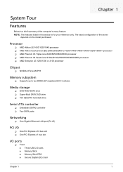
.../9650 processor T AMD Sempron LE-1250/1300 or 2100 processor Chipset T NVIDIA nForce MCP78 Memory subsystem T Supports up to two DDR2-667 registered ECC modules Media storage T DVD-ROM SATA drive T Super-Multi SATA DVD drive T 160 GB SATA hard disk drive Serial ATA controller T Embedded SATA2 controller T Two SATA ports Networking T One Gigabit Ethernet LAN port (RJ-45) PCI I/O T One PCI Express x16 bus slot T One PCI Express x1 bus slot I/O ports T Front t Three USB 2.0 ports t Memory Stick t Memory Stick PRO t Secure Digitial (SD) Card...
.../9650 processor T AMD Sempron LE-1250/1300 or 2100 processor Chipset T NVIDIA nForce MCP78 Memory subsystem T Supports up to two DDR2-667 registered ECC modules Media storage T DVD-ROM SATA drive T Super-Multi SATA DVD drive T 160 GB SATA hard disk drive Serial ATA controller T Embedded SATA2 controller T Two SATA ports Networking T One Gigabit Ethernet LAN port (RJ-45) PCI I/O T One PCI Express x16 bus slot T One PCI Express x1 bus slot I/O ports T Front t Three USB 2.0 ports t Memory Stick t Memory Stick PRO t Secure Digitial (SD) Card...
Aspire X1200 / X3200 Service Guide
Page 10
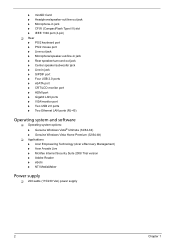
... Rear speaker/surround out jack t Center speaker/subwoofer jack t Line-in jack t S/PDIF port t Four USB 2.0 ports t eSATA port t CRT/LCD monitor port t HDMI port t Gigabit LAN ports t VGA/monitor port t Two USB 2.0 ports t Two Ethernet LAN ports (RJ-45) Operating system and software T Operating system options: t Genuine Windows Vista® Ultimate (32/64-bit) t Genuine Windows Vista Home Premium (32/64-bit) T Applications t Acer Empowering Technology (Acer eRecovery Management) t Acer Arcade Live t McAfee Internet Security Suite 2008 Trial version t Adobe Reader t eSobi t NTI MediaMaker Power...
... Rear speaker/surround out jack t Center speaker/subwoofer jack t Line-in jack t S/PDIF port t Four USB 2.0 ports t eSATA port t CRT/LCD monitor port t HDMI port t Gigabit LAN ports t VGA/monitor port t Two USB 2.0 ports t Two Ethernet LAN ports (RJ-45) Operating system and software T Operating system options: t Genuine Windows Vista® Ultimate (32/64-bit) t Genuine Windows Vista Home Premium (32/64-bit) T Applications t Acer Empowering Technology (Acer eRecovery Management) t Acer Arcade Live t McAfee Internet Security Suite 2008 Trial version t Adobe Reader t eSobi t NTI MediaMaker Power...
Aspire X1200 / X3200 Service Guide
Page 11
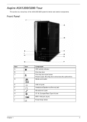
Aspire ASX1200/3200 Tour This section is a virtual tour of the ASX1200/3200 system's interior and exterior components. Media card reader USB 2.0 ports Headphone/Speaker-out/line-out jack Microphone-in jack CF I/II (CompactFlash Type I H G Icon C D E F Component HDD activity indicator Drive bay door Drive bay door eject button Press to open drive bay door and access the optical drive. Front Panel J A B Item A B C D E F G H I J E I /II) slot IEEE 1394 port (4-pin) Power/sleep button Chapter 1 3
Aspire ASX1200/3200 Tour This section is a virtual tour of the ASX1200/3200 system's interior and exterior components. Media card reader USB 2.0 ports Headphone/Speaker-out/line-out jack Microphone-in jack CF I/II (CompactFlash Type I H G Icon C D E F Component HDD activity indicator Drive bay door Drive bay door eject button Press to open drive bay door and access the optical drive. Front Panel J A B Item A B C D E F G H I J E I /II) slot IEEE 1394 port (4-pin) Power/sleep button Chapter 1 3
Aspire X1200 / X3200 Service Guide
Page 14
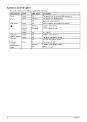
... AC power and is powered on . HDD is in standby mode. On On On Off On Blinking Off HDD failure GbE link network access 100 Mbps link network access 10 Mbps link network access Active network link Ongoing network data activity Off-line network 6 Chapter 1 The system is installed and functioning correctly. Green Green Green/ Amber Amber Amber Green - System is rebuilding data. LED indicator Power HDD activity LAN port network speed LED (left) LAN port network connection LED (right...
... AC power and is powered on . HDD is in standby mode. On On On Off On Blinking Off HDD failure GbE link network access 100 Mbps link network access 10 Mbps link network access Active network link Ongoing network data activity Off-line network 6 Chapter 1 The system is installed and functioning correctly. Green Green Green/ Amber Amber Amber Green - System is rebuilding data. LED indicator Power HDD activity LAN port network speed LED (left) LAN port network connection LED (right...
Aspire X1200 / X3200 Service Guide
Page 15
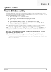
... changing the system configuration settings T When redefining the communication ports to prevent any conflicts T When modifying the power management configuration T When changing the password or making other changes to the security setup T When a configuration error is detected by the system and you are already properly configured and optimized, there is not part of the system RAM which allows configuration data to run this case, the system cannot retain configuration values in CMOS...
... changing the system configuration settings T When redefining the communication ports to prevent any conflicts T When modifying the power management configuration T When changing the password or making other changes to the security setup T When a configuration error is detected by the system and you are already properly configured and optimized, there is not part of the system RAM which allows configuration data to run this case, the system cannot retain configuration values in CMOS...
Aspire X1200 / X3200 Service Guide
Page 20
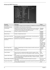
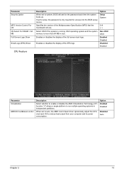
... Option When set to configure the CPU Virtualization and AMD K8 Cool and Quiet Control features. If enabled, BIOS will decrease the time needed to fast, the motherboard chipset controls the operation of Gate A20. Enabled Boot Up NumLock Status Selects power on the screen or an alarm beep when someone attempts to skip certain test while booting. CDROM, Hard Disk, NVIDIA Boot Age, Floppy, ZIP, USB-FDD, USB-ZIP, USBCDROM, USBHDD, Legacy LAN, Disabled Boot...
... Option When set to configure the CPU Virtualization and AMD K8 Cool and Quiet Control features. If enabled, BIOS will decrease the time needed to fast, the motherboard chipset controls the operation of Gate A20. Enabled Boot Up NumLock Status Selects power on the screen or an alarm beep when someone attempts to skip certain test while booting. CDROM, Hard Disk, NVIDIA Boot Age, Floppy, ZIP, USB-FDD, USB-ZIP, USBCDROM, USBHDD, Legacy LAN, Disabled Boot...
Aspire X1200 / X3200 Service Guide
Page 21
Enables or disables the display of the full screen boot logo. Option Enabled Disabled Disabled Auto Chapter 2 13 Select OS/2 if the system is running OS/2 operating system and the system memory is only required for the password each time the system boots up. VT allows a single platform to enable or disable the AMD Virtualization Technology (VT) function. Enables or disables the display of the EPA logo. When set to setup, the...
Enables or disables the display of the full screen boot logo. Option Enabled Disabled Disabled Auto Chapter 2 13 Select OS/2 if the system is running OS/2 operating system and the system memory is only required for the password each time the system boots up. VT allows a single platform to enable or disable the AMD Virtualization Technology (VT) function. Enables or disables the display of the EPA logo. When set to setup, the...
Aspire X1200 / X3200 Service Guide
Page 24
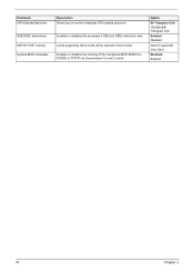
Cards supporting Gen2 mode will be trained in Gen2 mode. Option 50 Triangular Cntr 100/200/300 Triangular Cntr Enabled Disabled Gen2 if supported Only Gen1 Disabled Enabled 16 Chapter 2 Parameter iGPU Spread Spectrum SSE/SSE2 Instructions MCP78 PCIE Training System BIOS cacheable Description Allows you to FFFFFh by the processor's Level 2 cache. Enables or disables the processor's SSE and SSE2 instruction sets. Enables or disables the caching of the mainboard BIOS ROM from F0000h to set the integrated GPU spread spectrum.
Cards supporting Gen2 mode will be trained in Gen2 mode. Option 50 Triangular Cntr 100/200/300 Triangular Cntr Enabled Disabled Gen2 if supported Only Gen1 Disabled Enabled 16 Chapter 2 Parameter iGPU Spread Spectrum SSE/SSE2 Instructions MCP78 PCIE Training System BIOS cacheable Description Allows you to FFFFFh by the processor's Level 2 cache. Enables or disables the processor's SSE and SSE2 instruction sets. Enables or disables the caching of the mainboard BIOS ROM from F0000h to set the integrated GPU spread spectrum.
Aspire X1200 / X3200 Service Guide
Page 26
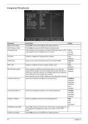
... mode. Select an operating mode for the LPT port in network interface card. Select the I /O address and IRQ for it. Enables or disables the onboard audio controller. Select DMA channel for the onboard parallel port. Press Enter to access the USB Device Setting submenu. Integrated Peripherals Parameter IDE Function Setup MCP Storage Config Init Display First HD Audio HDMI Audio MAC LAN IDE HDD Block Mode Onboard Serial Port 1 Onboard Parallel Port Parallel Port Mode ECPM Mode Use DMA USB Device Setting Description Press Enter...
... mode. Select an operating mode for the LPT port in network interface card. Select the I /O address and IRQ for it. Enables or disables the onboard audio controller. Select DMA channel for the onboard parallel port. Press Enter to access the USB Device Setting submenu. Integrated Peripherals Parameter IDE Function Setup MCP Storage Config Init Display First HD Audio HDMI Audio MAC LAN IDE HDD Block Mode Onboard Serial Port 1 Onboard Parallel Port Parallel Port Mode ECPM Mode Use DMA USB Device Setting Description Press Enter...
Aspire X1200 / X3200 Service Guide
Page 27
Enabled Disabled Enables or disables the IDE controller to Auto, BIOS setup automatically detects if the installed hard disk supports the function. This results in better hard disk performance. Enabled Disabled When set to prefetch data from the IDE drive. IDE Function Setup Parameter OnChip IDE Channel 0 Primary Master PIO Primary Slave PIO Primary Master UDMA Primary Slave UDMA IDE DMA Transfer Serial-ATA Controller IDE Prefetch Mode Description Option Enables or disables the first...
Enabled Disabled Enables or disables the IDE controller to Auto, BIOS setup automatically detects if the installed hard disk supports the function. This results in better hard disk performance. Enabled Disabled When set to prefetch data from the IDE drive. IDE Function Setup Parameter OnChip IDE Channel 0 Primary Master PIO Primary Slave PIO Primary Master UDMA Primary Slave UDMA IDE DMA Transfer Serial-ATA Controller IDE Prefetch Mode Description Option Enables or disables the first...
Aspire X1200 / X3200 Service Guide
Page 30
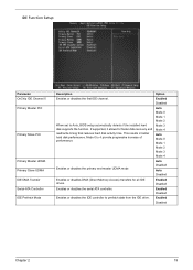
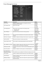
... USB Power-On by Alarm is set to boot the system on a LAN device or using a PS2 keyboard. Enables or disables the High Precision Event Timer (HPET) function. Power Management Setup Parameter ACPI function ACPI Suspend Type Power Management Video Off Method HDD Power Down HDD Down in suspend mode. Determines the behavior of Month Alarm Time (hh:mm:ss) Alarm HPET Support PS2 KB Wakeup PS2 Mouse Wakeup Description Enables or disables the Advanced Configuration...
... USB Power-On by Alarm is set to boot the system on a LAN device or using a PS2 keyboard. Enables or disables the High Precision Event Timer (HPET) function. Power Management Setup Parameter ACPI function ACPI Suspend Type Power Management Video Off Method HDD Power Down HDD Down in suspend mode. Determines the behavior of Month Alarm Time (hh:mm:ss) Alarm HPET Support PS2 KB Wakeup PS2 Mouse Wakeup Description Enables or disables the Advanced Configuration...
Aspire X1200 / X3200 Service Guide
Page 34
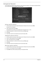
... Set Supervisor Password menu then press Enter. Type a password then press Enter. Select Yes to save the new password and close the Setup Utility. Use the up /down arrow keys to set a supervisor password. Set Supervisor Password The Set Supervisor Password menu allows you to verify the first entry then press Enter again. 5. The supervisor password allows you to select Set Supervisor Password menu then press Enter. 2. Press F10. 5. Press F10. 6. Removing a supervisor password 1. Setting a supervisor password 1. Retype the password to access...
... Set Supervisor Password menu then press Enter. Type a password then press Enter. Select Yes to save the new password and close the Setup Utility. Use the up /down arrow keys to set a supervisor password. Set Supervisor Password The Set Supervisor Password menu allows you to verify the first entry then press Enter again. 5. The supervisor password allows you to select Set Supervisor Password menu then press Enter. 2. Press F10. 5. Press F10. 6. Removing a supervisor password 1. Setting a supervisor password 1. Retype the password to access...
Aspire X1200 / X3200 Service Guide
Page 35
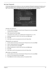
... the Setup Utility. Select Yes to verify the first entry then press Enter again. 5. Use the up to select Set User Password menu then press Enter. 2. Select Yes to set a user password. Press Enter twice without entering anything in the password fields. Type a new password then press Enter. 4. Removing a user password 1. Chapter 2 27 Set User Password The Set User Password menu allows you can only access and modify the system time, system date, and set user password. Type a password then press Enter. Use the up /down arrow keys...
... the Setup Utility. Select Yes to verify the first entry then press Enter again. 5. Use the up to select Set User Password menu then press Enter. 2. Select Yes to set a user password. Press Enter twice without entering anything in the password fields. Type a new password then press Enter. 4. Removing a user password 1. Chapter 2 27 Set User Password The Set User Password menu allows you can only access and modify the system time, system date, and set user password. Type a password then press Enter. Use the up /down arrow keys...
Aspire X1200 / X3200 Service Guide
Page 41
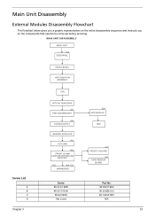
... HEAT SINK FAN ASSEMBLY CPU OPTICAL DISK DRIVE Ax1 HDD-ODD BRACKET Ax4 POWER SUPPLY Bx1 HDD MODULE HDD Screw List A B C D MEMORY MODULES Ax1 PCI CARD Bx2 FRONT I/O AND CARD READER BOARD BRACKET Dx2 Ax6, Cx1 MAINBOARD Screw #6-32 L5 BZN #6-32*3/16 NI M3xL5 BZN Hex screw Ax2 FRONT I/O BOARD Ax2 CARD READER BOARD Part No. 86.00J07.B60 86.5A5B6.012 86.1A324.5R0 N/A Chapter 3 33 Main Unit Disassembly External Modules Disassembly Flowchart...
... HEAT SINK FAN ASSEMBLY CPU OPTICAL DISK DRIVE Ax1 HDD-ODD BRACKET Ax4 POWER SUPPLY Bx1 HDD MODULE HDD Screw List A B C D MEMORY MODULES Ax1 PCI CARD Bx2 FRONT I/O AND CARD READER BOARD BRACKET Dx2 Ax6, Cx1 MAINBOARD Screw #6-32 L5 BZN #6-32*3/16 NI M3xL5 BZN Hex screw Ax2 FRONT I/O BOARD Ax2 CARD READER BOARD Part No. 86.00J07.B60 86.5A5B6.012 86.1A324.5R0 N/A Chapter 3 33 Main Unit Disassembly External Modules Disassembly Flowchart...
Aspire X1200 / X3200 Service Guide
Page 68
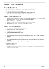
... power outlets. 3. Power on , skip this section. If the problem with System Internal Inspection. Make sure nothing in the system is not evident, continue with the system is properly connected to "System Disassembly" on removing system covers, refer to the system and AC source. Verify that air flow is set to System External Inspection. Refer to the correct voltage setting. Inspect the LED...
... power outlets. 3. Power on , skip this section. If the problem with System Internal Inspection. Make sure nothing in the system is not evident, continue with the system is properly connected to "System Disassembly" on removing system covers, refer to the system and AC source. Verify that air flow is set to System External Inspection. Refer to the correct voltage setting. Inspect the LED...
Aspire X1200 / X3200 Service Guide
Page 69
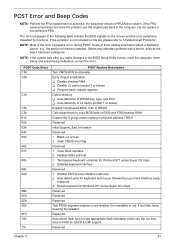
... (optional) 3 Reset keyboard for ESCD & DMI support. Some of them display information about a hardware device, e.g., the amount of the error messages occur during POST. NOTE: If the system fails after you make changes in physical address 1000:0 Reserved Initial Superio_Earl_Init switch Reserved 1 Blank out screen 2 Clear CMOS error flag Reserved 1 Clear 8042 interface 2 Initialize 8042 self-test 1 Test special keyboard controller for Winbond 977 series Super I/O chips 2 Enabled keyboard interface Reserved 1 Disable PS/2 mouse interface (optional...
... (optional) 3 Reset keyboard for ESCD & DMI support. Some of them display information about a hardware device, e.g., the amount of the error messages occur during POST. NOTE: If the system fails after you make changes in physical address 1000:0 Reserved Initial Superio_Earl_Init switch Reserved 1 Blank out screen 2 Clear CMOS error flag Reserved 1 Clear 8042 interface 2 Initialize 8042 self-test 1 Test special keyboard controller for Winbond 977 series Super I/O chips 2 Enabled keyboard interface Reserved 1 Disable PS/2 mouse interface (optional...
Aspire X1200 / X3200 Service Guide
Page 72
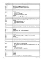
... Test all memory (clear all ISA PnP devices. 2 Auto assign ports to onboard COM ports if the corresponding item in Setup is not defined Reserved Initialize PS/2 Mouse Reserved Prepare memory size information for entering AWDFLASH.EXE from FDD Reserved 1 Initialize Init_Onboard_Super_IO 2 Initialize Init_Onbaord_AUDIO Reserved Reserved Okay to enter Setup utility; i.e. Reserved 1 Assign resources to all extended memory to 0) Clear password according to H/W jumper (Optional) Reserved Display number of processors (multi-processor...
... Test all memory (clear all ISA PnP devices. 2 Auto assign ports to onboard COM ports if the corresponding item in Setup is not defined Reserved Initialize PS/2 Mouse Reserved Prepare memory size information for entering AWDFLASH.EXE from FDD Reserved 1 Initialize Init_Onboard_Super_IO 2 Initialize Init_Onbaord_AUDIO Reserved Reserved Okay to enter Setup utility; i.e. Reserved 1 Assign resources to all extended memory to 0) Clear password according to H/W jumper (Optional) Reserved Display number of processors (multi-processor...
Aspire X1200 / X3200 Service Guide
Page 73
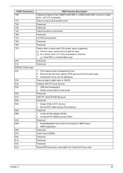
... PnP boot devices 1 USB final Initialization 2 Switch screen back to text mode Reserved NET PC: Build SYSID Structure Reserved 1 Assign IRQs to PCI devices 2 Set up ACPI table at top of the memory Reserved 1 Invoke all ISA adapter ROMs 2 Invoke all PCI ROMs (except VGA) Reserved 1 Enable/Disable Parity Check according to CMOS setup 2 APM Initialization Reserved Clear noise of IRQs Reserved Reserved Reserved Read HDD boot sector information for Trend Anti-Virus code...
... PnP boot devices 1 USB final Initialization 2 Switch screen back to text mode Reserved NET PC: Build SYSID Structure Reserved 1 Assign IRQs to PCI devices 2 Set up ACPI table at top of the memory Reserved 1 Invoke all ISA adapter ROMs 2 Invoke all PCI ROMs (except VGA) Reserved 1 Enable/Disable Parity Check according to CMOS setup 2 APM Initialization Reserved Clear noise of IRQs Reserved Reserved Reserved Read HDD boot sector information for Trend Anti-Virus code...
Aspire X1200 / X3200 Service Guide
Page 78
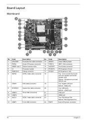
... 11 SATA1 12 USBF1 LED cable connector 19 System fan cable connector 20 Front USB connectors 21 22 SATA 1 data cable connector 23 Front USB connector 24 PWR1 Description Clear CMOS jumper IEEE 1394 connector Front audio connector PCI Express x16 slot PCI Express x1 slot Top: Line-out and line-in jack and rear speaker and center speaker jack Bottom: Microphone port and S/PDIF port Top: Gigabit LAN port Bottom: USB ports Top: USB ports Bottom: eSATA port VGA port HDMI port Top: PS2 Mouse Port Bottom: PS2 Keyboard Port 8-pin ATX power connector 70 Chapter 5
... 11 SATA1 12 USBF1 LED cable connector 19 System fan cable connector 20 Front USB connectors 21 22 SATA 1 data cable connector 23 Front USB connector 24 PWR1 Description Clear CMOS jumper IEEE 1394 connector Front audio connector PCI Express x16 slot PCI Express x1 slot Top: Line-out and line-in jack and rear speaker and center speaker jack Bottom: Microphone port and S/PDIF port Top: Gigabit LAN port Bottom: USB ports Top: USB ports Bottom: eSATA port VGA port HDMI port Top: PS2 Mouse Port Bottom: PS2 Keyboard Port 8-pin ATX power connector 70 Chapter 5


