

AL511 Service Guide
Page 3
... Off Off LED Green Yellow Yellow Off 3 Adjust decrease. 3. Power ON/OFF switch, push to ON and push to C-2 LED definition table) 2. CONTROLS B-1 Control panel (monitor front panel) 1. Function select counter-clockwise. 5. B. Power LED, ( Please refer to OFF. (toggle switch) C. Function select clockwise. 6.
... Off Off LED Green Yellow Yellow Off 3 Adjust decrease. 3. Power ON/OFF switch, push to ON and push to C-2 LED definition table) 2. CONTROLS B-1 Control panel (monitor front panel) 1. Function select counter-clockwise. 5. B. Power LED, ( Please refer to OFF. (toggle switch) C. Function select clockwise. 6.
AL511 Service Guide
Page 7
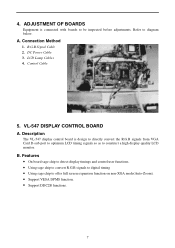
... CONTROL BOARD A. DC Power Cable 3. A. LCD Lamp Cables 4. Description The VL-547 display control board is connected with boards to construct a high display quality LCD monitor. Connection Method 1. B. ADJUSTMENT OF BOARDS Equipment is design to directly convert the R.G.B signals from VGA Card D-sub port to optimum LCD timing signals so as...
... CONTROL BOARD A. DC Power Cable 3. A. LCD Lamp Cables 4. Description The VL-547 display control board is connected with boards to construct a high display quality LCD monitor. Connection Method 1. B. ADJUSTMENT OF BOARDS Equipment is design to directly convert the R.G.B signals from VGA Card D-sub port to optimum LCD timing signals so as...

AL511 Service Guide
Page 8
A new standalone on a single chip. Other features include a brand new high-end scaler, Active Color Management, a flexible OSD, Autoadjust, SureSyncTM and independent monitoring of monitors. 8 The cost-effective s9050-100 is highly-integrated display processors. Block Diagram (Control CKT) System Level Interface with Integrated Timing Controller C-1 Sage Operation The s9050-...
A new standalone on a single chip. Other features include a brand new high-end scaler, Active Color Management, a flexible OSD, Autoadjust, SureSyncTM and independent monitoring of monitors. 8 The cost-effective s9050-100 is highly-integrated display processors. Block Diagram (Control CKT) System Level Interface with Integrated Timing Controller C-1 Sage Operation The s9050-...
AL511 Service Guide
Page 12
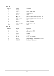
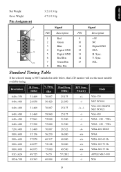
F-3 J2 Pin NO. 1 2 3 4 5 6 7 8 9 10 F-4 J3 Pin NO. 1 2 3 4 5 6 7 Signal NONE LED-Y LED-G GND KEY-UP KEY-Down KEY-R KEY-L KEY-POWER GND Signal +5V +5V GND GND BLON MUTE BRIGHT Comment Power saving mode Monitor is ON GND Function select counter-clockwise key Function select counter-clockwise key Adjust up key Adjust down key Power ON/OFF key GND Comment VL547 power input VL547 power input Ground Ground Back Light ON/OFF. Audio amplifier control signal (No use) Brightness Adjustment. 12
F-3 J2 Pin NO. 1 2 3 4 5 6 7 8 9 10 F-4 J3 Pin NO. 1 2 3 4 5 6 7 Signal NONE LED-Y LED-G GND KEY-UP KEY-Down KEY-R KEY-L KEY-POWER GND Signal +5V +5V GND GND BLON MUTE BRIGHT Comment Power saving mode Monitor is ON GND Function select counter-clockwise key Function select counter-clockwise key Adjust up key Adjust down key Power ON/OFF key GND Comment VL547 power input VL547 power input Ground Ground Back Light ON/OFF. Audio amplifier control signal (No use) Brightness Adjustment. 12

AL511 Service Guide
Page 14
... Definition D1 Green for DC power off mode. 14 D. Connector pin Assignment D-1 J5 Pin NO. 1 2 Signal NONE LED-Y Comment Power saving mode. 3 LED-G 4,10 GND Monitor on mode. Yellow for ON mode;
... Definition D1 Green for DC power off mode. 14 D. Connector pin Assignment D-1 J5 Pin NO. 1 2 Signal NONE LED-Y Comment Power saving mode. 3 LED-G 4,10 GND Monitor on mode. Yellow for ON mode;
AL511 Service Guide
Page 17
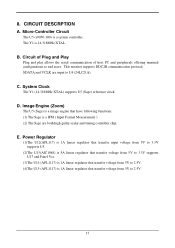
.... (1) The Sage is a image engine that transfer voltage from 5V to 2.5V. 17 Micro-Controller Circuit The U5 (s9050-100) is 14.318MHz XTAL. This monitor supports DDC2B communication protocal. C.
.... (1) The Sage is a image engine that transfer voltage from 5V to 2.5V. 17 Micro-Controller Circuit The U5 (s9050-100) is 14.318MHz XTAL. This monitor supports DDC2B communication protocal. C.
AL511 Service Guide
Page 18
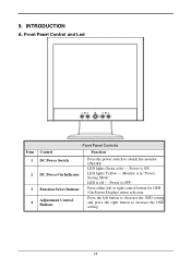
Power is in "Power Saving Mode". Front Panel Control and Led Item 1 2 3 4 Front Panel Controls Control Function DC Power Switch DC Power-On Indicator Function Select Buttons Adjustment Control Buttons Press the power switch to increase the OSD setting. 18 INTRODUCTION A. 9. LED lights Green color --- Monitor is ON. Press either left button to decrease the OSD setting and press the right button to switch the monitor ON/OFF. Press the left or right control button for OSD (On Screen Display) menu selection. LED lights Yellow --- Power is off --- LED is OFF.
Power is in "Power Saving Mode". Front Panel Control and Led Item 1 2 3 4 Front Panel Controls Control Function DC Power Switch DC Power-On Indicator Function Select Buttons Adjustment Control Buttons Press the power switch to increase the OSD setting. 18 INTRODUCTION A. 9. LED lights Green color --- Monitor is ON. Press either left button to decrease the OSD setting and press the right button to switch the monitor ON/OFF. Press the left or right control button for OSD (On Screen Display) menu selection. LED lights Yellow --- Power is off --- LED is OFF.
AL511 User Guide
Page 1
Table of Contents Preface ...2 Chapter 1 Installation 4 Unpacking ...4 Connecting the LCD Monitor and Base 4 Viewing Angle Adjustment ...4 Detaching LCD Monitor from Its Stand 5 Interface for Arm Applications 5 Connecting the Display to your Computer 5 Connecting the AC Power...7 Setting Up the LCD Monitor...7 Power Management System...7 Chapter 2 Display Controls 8 User Controls ...8 Adjusting the Monitor's Display 8 Function Description...10 Chapter 3 Technical Information 12 Specifications...12 Standard Timing Table ...15 Troubleshooting...17
Table of Contents Preface ...2 Chapter 1 Installation 4 Unpacking ...4 Connecting the LCD Monitor and Base 4 Viewing Angle Adjustment ...4 Detaching LCD Monitor from Its Stand 5 Interface for Arm Applications 5 Connecting the Display to your Computer 5 Connecting the AC Power...7 Setting Up the LCD Monitor...7 Power Management System...7 Chapter 2 Display Controls 8 User Controls ...8 Adjusting the Monitor's Display 8 Function Description...10 Chapter 3 Technical Information 12 Specifications...12 Standard Timing Table ...15 Troubleshooting...17

AL511 User Guide
Page 2
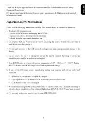
... correctness of the manufacturer. Canadian DOC Notice 2 All rights are designed to provide reasonable protection against harmful interference in setting up and using the LCD Monitor. This equipment generates, uses, and can be used in accordance with the limits for a Class B digital device, pursuant to Part 15 of the following measures...
... correctness of the manufacturer. Canadian DOC Notice 2 All rights are designed to provide reasonable protection against harmful interference in setting up and using the LCD Monitor. This equipment generates, uses, and can be used in accordance with the limits for a Class B digital device, pursuant to Part 15 of the following measures...
AL511 User Guide
Page 3
...75 mm2 must be used. 8. If any nature should be performed by yourself. For a nominal current up to the LCD screen. To clean LCD Monitor screen; -- Do not remove the cover or attempt to a power outlet. Cet appareil numérique de la classe B repecte toutes les exigences du... Règlement sur le matériel brouilleur du Canada. Do not place the LCD Monitor near a window. For use . 1. Excess pressure may cause permanent damage to rain water, moisture or sunlight can severely damage it. 3. ENGLISH This...
...75 mm2 must be used. 8. If any nature should be performed by yourself. For a nominal current up to the LCD screen. To clean LCD Monitor screen; -- Do not remove the cover or attempt to a power outlet. Cet appareil numérique de la classe B repecte toutes les exigences du... Règlement sur le matériel brouilleur du Canada. Do not place the LCD Monitor near a window. For use . 1. Excess pressure may cause permanent damage to rain water, moisture or sunlight can severely damage it. 3. ENGLISH This...
AL511 User Guide
Page 4
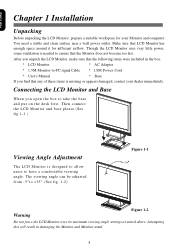
... to take the base and put on the desk first. Make sure that the following items were included in damaging the Monitor and Monitor stand. 4 After you find that the Monitor does not become too hot. You need a stable and clean surface near a wall power outlet. Attempting this will result... designed to allow users to -PC signal Cable * 1.8M Power Cord * User's Manual * Base If you unpack the LCD Monitor, make sure that LCD Monitor has enough space around it for your dealer immediately. The viewing angle can be adjusted from -5°t o +35°. (See fig. 1-2) Figure 1-1 Warning ...
... to take the base and put on the desk first. Make sure that the following items were included in damaging the Monitor and Monitor stand. 4 After you find that the Monitor does not become too hot. You need a stable and clean surface near a wall power outlet. Attempting this will result... designed to allow users to -PC signal Cable * 1.8M Power Cord * User's Manual * Base If you unpack the LCD Monitor, make sure that LCD Monitor has enough space around it for your dealer immediately. The viewing angle can be adjusted from -5°t o +35°. (See fig. 1-2) Figure 1-1 Warning ...

AL511 User Guide
Page 5
...hinge bracket 2. Unscrew screws of the signal cable to the VGA port on your PC. 4. These specifications meet the VESA Flat Panel Monitor Physical Mounting Interface Standard (paragraphs 2.1 and 2.1.3, version 1, dated 13 November 1997). Connect one end of this LCD display has four ...with FCC regulations when a non-ferrite-core video cable is included in order to comply with FCC regulations. ENGLISH Detaching LCD Monitor from LCD monitor (See fig. 1-3) Figure 1-3 Interface for Arm Applications Before installing to mounting device, please refer to Fig.1-3. Figure 1-5 ...
...hinge bracket 2. Unscrew screws of the signal cable to the VGA port on your PC. 4. These specifications meet the VESA Flat Panel Monitor Physical Mounting Interface Standard (paragraphs 2.1 and 2.1.3, version 1, dated 13 November 1997). Connect one end of this LCD display has four ...with FCC regulations when a non-ferrite-core video cable is included in order to comply with FCC regulations. ENGLISH Detaching LCD Monitor from LCD monitor (See fig. 1-3) Figure 1-3 Interface for Arm Applications Before installing to mounting device, please refer to Fig.1-3. Figure 1-5 ...
AL511 User Guide
Page 7
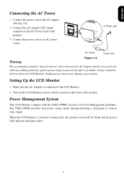
...output connector to the DC Power Jack of sudden voltage variations from reaching the LCD Monitor. Setting Up the LCD Monitor 1. Make sure the AC Adapter is in power saving mode, the monitor screen will be blank and the power LED indicator will light yellow. 7 Warning ...adding protection against power surges to the LCD Monitor. 2. Turn on the LCD Monitor's power switch, located on the bezel of the monitor. When the LCD Monitor is connected to prevent the effects of the monitor. 3. Power Management System This LCD Monitor complies with the VESA DPMS (version 1.0) Power...
...output connector to the DC Power Jack of sudden voltage variations from reaching the LCD Monitor. Setting Up the LCD Monitor 1. Make sure the AC Adapter is in power saving mode, the monitor screen will be blank and the power LED indicator will light yellow. 7 Warning ...adding protection against power surges to the LCD Monitor. 2. Turn on the LCD Monitor's power switch, located on the bezel of the monitor. When the LCD Monitor is connected to prevent the effects of the monitor. 3. Power Management System This LCD Monitor complies with the VESA DPMS (version 1.0) Power...
AL511 User Guide
Page 8
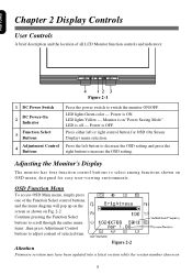
... shown on OSD menu, designed for OSD (On Screen Display) menu selection. Power is in "Power Saving Mode". Adjusting the Monitor's Display The monitor has four function control buttons to increase the OSD setting. LED is ON. LED lights Yellow --- OSD Function Menu To access ...press the right button to select among functions shown on 8 Chapter 2 Display Controls User Controls A brief description and the location of all LCD Monitor function controls and indicators: Figure 2-1 1 DC Power Switch DC Power-On 2 Indicator 3 Function Select Buttons 4 Adjustment Control Buttons Press the ...
... shown on OSD menu, designed for OSD (On Screen Display) menu selection. Power is in "Power Saving Mode". Adjusting the Monitor's Display The monitor has four function control buttons to increase the OSD setting. LED is ON. LED lights Yellow --- OSD Function Menu To access ...press the right button to select among functions shown on 8 Chapter 2 Display Controls User Controls A brief description and the location of all LCD Monitor function controls and indicators: Figure 2-1 1 DC Power Switch DC Power-On 2 Indicator 3 Function Select Buttons 4 Adjustment Control Buttons Press the ...
AL511 User Guide
Page 15
... -/+,-/- XGA 15 Sync. 10 7 Green Rtn 15 SCL 8 Blue Rtn Standard Timing Table If the selected timing is NOT included in table below, this LCD monitor will use the most suitable available timing. Polarity Mode 640 x 350 31.469 70.087 25.175 +/- Sync. 6 Red Rtn 14 V.
... -/+,-/- XGA 15 Sync. 10 7 Green Rtn 15 SCL 8 Blue Rtn Standard Timing Table If the selected timing is NOT included in table below, this LCD monitor will use the most suitable available timing. Polarity Mode 640 x 350 31.469 70.087 25.175 +/- Sync. 6 Red Rtn 14 V.
AL511 User Guide
Page 17
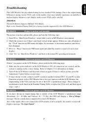
... Hz), the OSD will display a message "No Input Signal". 17 PROBLEM Picture is unclear and unstable The picture is no picture on LCD Monitor If there's no picture, press the Adjustment Control button several times. 3. Check the screen to the normal PC operating environment. PROBLEM There is..., please perform the following steps: 1. Please change to its most clear display. 4. Due to the Standard Timing Table for information on the LCD Monitor, please perform the following steps : 1. If there are secured, and the system is selected. Move to "Phase" function in OSD menu again...
... Hz), the OSD will display a message "No Input Signal". 17 PROBLEM Picture is unclear and unstable The picture is no picture on LCD Monitor If there's no picture, press the Adjustment Control button several times. 3. Check the screen to the normal PC operating environment. PROBLEM There is..., please perform the following steps: 1. Please change to its most clear display. 4. Due to the Standard Timing Table for information on the LCD Monitor, please perform the following steps : 1. If there are secured, and the system is selected. Move to "Phase" function in OSD menu again...


