
Intel Smart Response Installation Guide
Page 1
Intel Smart Response Technology Installation Guide This motherboard supports Intel Smart Response Technology. UI setup instruction: 1. Boot system to show the newly accelerated system configuration. * Intel® will refresh to desktop, open , click on the "Enable Acceleration" button on the GUI panel. 5. Once open RST GUI from either Start Menu or by step instructions below. After clicking OK button, SRT will enable automatically, and the RST GUI will update the new version RST driver in...
Intel Smart Response Technology Installation Guide This motherboard supports Intel Smart Response Technology. UI setup instruction: 1. Boot system to show the newly accelerated system configuration. * Intel® will refresh to desktop, open , click on the "Enable Acceleration" button on the GUI panel. 5. Once open RST GUI from either Start Menu or by step instructions below. After clicking OK button, SRT will enable automatically, and the RST GUI will update the new version RST driver in...
Intel Rapid Storage Guide
Page 13
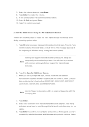
... Intel Rapid Storage Technology driver during text-mode phase). Nothing will temporarily continue loading drivers. This message appears at the beginning of available SCSI adapters. Use the Floppy Configuration Utility to confirm your exit. Press Enter to create a floppy disk with a screen asking you have successfully installed the driver and Windows setup should continue. 7. At the prompt press Y to create the volume. 9. Press Y to load support for mass storage device(s). 2. At this...
... Intel Rapid Storage Technology driver during text-mode phase). Nothing will temporarily continue loading drivers. This message appears at the beginning of available SCSI adapters. Use the Floppy Configuration Utility to confirm your exit. Press Enter to create a floppy disk with a screen asking you have successfully installed the driver and Windows setup should continue. 7. At the prompt press Y to create the volume. 9. Press Y to load support for mass storage device(s). 2. At this...
RAID Installation Guide
Page 7
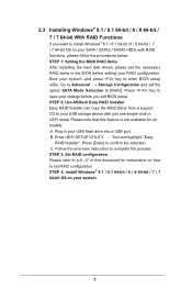
... your SATA / SATA2 / SATA3 HDDs with just one simple click in UEFI setup. Press key to your RAID configuration. STEP 2: Use ASRock Easy RAID Installer Easy RAID Installer can copy the RAID driver from a support CD to save your change before setting your USB storage device with RAID functions, please follow the procedures below. STEP 4: Install Windows® 8.1 / 8.1 64-bit / 8 / 8 64-bit / 7 / 7 64-bit OS on your system, and press key to Advanced Storage Configuration and set RAID configuration. Boot your system. 7 Go to enter BIOS setup utility.
... your SATA / SATA2 / SATA3 HDDs with just one simple click in UEFI setup. Press key to your RAID configuration. STEP 2: Use ASRock Easy RAID Installer Easy RAID Installer can copy the RAID driver from a support CD to save your change before setting your USB storage device with RAID functions, please follow the procedures below. STEP 4: Install Windows® 8.1 / 8.1 64-bit / 8 / 8 64-bit / 7 / 7 64-bit OS on your system, and press key to Advanced Storage Configuration and set RAID configuration. Boot your system. 7 Go to enter BIOS setup utility.
User Manual
Page 4
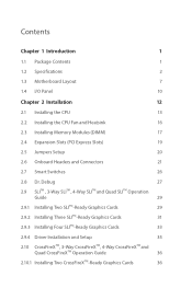
... 1.2 Specifications 2 1.3 Motherboard Layout 7 1.4 I/O Panel 10 Chapter 2 Installation 12 2.1 Installing the CPU 13 2.2 Installing the CPU Fan and Heatsink 16 2.3 Installing Memory Modules (DIMM) 17 2.4 Expansion Slots (PCI Express Slots) 19 2.5 Jumpers Setup 20 2.6 Onboard Headers and Connectors 21 2.7 Smart Switches 26 2.8 Dr. Debug 27 2.9 SLITM , 3-Way SLITM , 4-Way SLITM and Quad SLITM Operation Guide 29 2.9.1 Installing Two SLITM-Ready Graphics Cards 29 2.9.2 Installing Three SLITM-Ready Graphics Cards 31 2.9.3 Installing Four SLITM-Ready Graphics Cards 33...
... 1.2 Specifications 2 1.3 Motherboard Layout 7 1.4 I/O Panel 10 Chapter 2 Installation 12 2.1 Installing the CPU 13 2.2 Installing the CPU Fan and Heatsink 16 2.3 Installing Memory Modules (DIMM) 17 2.4 Expansion Slots (PCI Express Slots) 19 2.5 Jumpers Setup 20 2.6 Onboard Headers and Connectors 21 2.7 Smart Switches 26 2.8 Dr. Debug 27 2.9 SLITM , 3-Way SLITM , 4-Way SLITM and Quad SLITM Operation Guide 29 2.9.1 Installing Two SLITM-Ready Graphics Cards 29 2.9.2 Installing Three SLITM-Ready Graphics Cards 31 2.9.3 Installing Four SLITM-Ready Graphics Cards 33...
User Manual
Page 7
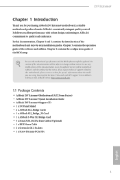
... Motherboard (ATX Form Factor) • ASRock Z97 Extreme9 Quick Installation Guide • ASRock Z97 Extreme9 Support CD • 1 x I/O Panel Shield • 2 x ASRock SLI_Bridge Cards • 1 x ASRock SLI_Bridge_3S Card • 1 x ASRock 3-Way SLI Bridge Card • 4 x Serial ATA (SATA) Data Cables (Optional) • 1 x HDD Saver Cable • 2 x Screws for M.2 Sockets • 1 x Screw for specific information about the model you are using. Chapter 3 contains the operation guide of the BIOS setup. In case any modifications of this documentation will be subject to change...
... Motherboard (ATX Form Factor) • ASRock Z97 Extreme9 Quick Installation Guide • ASRock Z97 Extreme9 Support CD • 1 x I/O Panel Shield • 2 x ASRock SLI_Bridge Cards • 1 x ASRock SLI_Bridge_3S Card • 1 x ASRock 3-Way SLI Bridge Card • 4 x Serial ATA (SATA) Data Cables (Optional) • 1 x HDD Saver Cable • 2 x Screws for M.2 Sockets • 1 x Screw for specific information about the model you are using. Chapter 3 contains the operation guide of the BIOS setup. In case any modifications of this documentation will be subject to change...
User Manual
Page 11
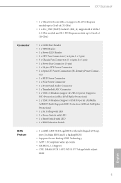
ment English 5 Z97 Extreme9 • 1 x Ultra M.2 Socket (M2_1), supports M.2 PCI Express module up to Gen2 x2 (10 Gb/s) Connector • 1 x COM Port Header • 1 x TPM Header • 1 x Power LED Header • 2 x CPU Fan Connectors (1 x 4-pin, 1 x 3-pin) • 3 x Chassis Fan Connectors (1 x 4-pin, 2 x 3-pin) • 1 x Power Fan Connector (3-pin) • 1 x 24 pin ATX Power Connector • 2 x 8 pin 12V Power Connectors (Hi-Density Power Connec- tor) • 1 x HDD Saver Connector • 1 x PCIe Power Connector • 1 x Front Panel Audio Connector • 1 x ...
ment English 5 Z97 Extreme9 • 1 x Ultra M.2 Socket (M2_1), supports M.2 PCI Express module up to Gen2 x2 (10 Gb/s) Connector • 1 x COM Port Header • 1 x TPM Header • 1 x Power LED Header • 2 x CPU Fan Connectors (1 x 4-pin, 1 x 3-pin) • 3 x Chassis Fan Connectors (1 x 4-pin, 2 x 3-pin) • 1 x Power Fan Connector (3-pin) • 1 x 24 pin ATX Power Connector • 2 x 8 pin 12V Power Connectors (Hi-Density Power Connec- tor) • 1 x HDD Saver Connector • 1 x PCIe Power Connector • 1 x Front Panel Audio Connector • 1 x ...

User Manual
Page 14
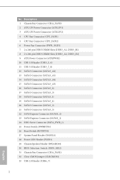
...) 15 SATA3 Connector (SATA3_A3) 16 SATA3 Connector (SATA3_0) 17 SATA3 Connector (SATA3_3) 18 SATA3 Connector (SATA3_1) 19 SATA3 Connector (SATA3_4) 20 SATA3 Connector (SATA3_2) 21 SATA3 Connector (SATA3_5) 22 SATA Express Connector (SATAE_2) 23 SATA Express Connector (SATAE_1) 24 HDD Saver Connector (SATA_PWR_1) 25 Power Switch (PWRBTN1) 26 Reset Switch (RSTBTN1) 27 System Panel Header (PANEL1) 28 Power LED Header (PLED1) 29 Chassis Speaker Header (SPEAKER1) 30 BIOS Selection Switch (BIOS_SEL1) 31 Chassis Fan Connector (CHA_FAN1) 32 Clear CMOS Jumper (CLRCMOS1) 33 USB 2.0 Header (USB6_7...
...) 15 SATA3 Connector (SATA3_A3) 16 SATA3 Connector (SATA3_0) 17 SATA3 Connector (SATA3_3) 18 SATA3 Connector (SATA3_1) 19 SATA3 Connector (SATA3_4) 20 SATA3 Connector (SATA3_2) 21 SATA3 Connector (SATA3_5) 22 SATA Express Connector (SATAE_2) 23 SATA Express Connector (SATAE_1) 24 HDD Saver Connector (SATA_PWR_1) 25 Power Switch (PWRBTN1) 26 Reset Switch (RSTBTN1) 27 System Panel Header (PANEL1) 28 Power LED Header (PLED1) 29 Chassis Speaker Header (SPEAKER1) 30 BIOS Selection Switch (BIOS_SEL1) 31 Chassis Fan Connector (CHA_FAN1) 32 Clear CMOS Jumper (CLRCMOS1) 33 USB 2.0 Header (USB6_7...

User Manual
Page 31
...) Serial Port Header (9-pin COM1) (see p.7, No. 39) 1 PCICLK FRAME PCIRST# LAD3 +3V LAD0 +3VSB GND GND SMB_CLK_MAIN SMB_DATA_MAIN LAD2 LAD1 GND S_PWRDWN# SERIRQ# GND This connector supports Trusted Platform Module (TPM) system, which can securely store keys, digital certificates, passwords, and data. Please connect the HDD Saver Cable to this connector when more than three graphics cards are installed. A TPM system also helps enhance network...
...) Serial Port Header (9-pin COM1) (see p.7, No. 39) 1 PCICLK FRAME PCIRST# LAD3 +3V LAD0 +3VSB GND GND SMB_CLK_MAIN SMB_DATA_MAIN LAD2 LAD1 GND S_PWRDWN# SERIRQ# GND This connector supports Trusted Platform Module (TPM) system, which can securely store keys, digital certificates, passwords, and data. Please connect the HDD Saver Cable to this connector when more than three graphics cards are installed. A TPM system also helps enhance network...

User Manual
Page 33
...-install IDE and SATA devices. Please re-install PCI-E devices or try using another VGA card. If the problem still exists, please install only one memory module or try using other slots. Please re-install the memory and CPU. Code Description 00 Please check if the CPU is used to IDE or SATA devices. Please re-install the CPU and memory then clear CMOS. If the problem still exists, please clear CMOS and try using other memory modules. If the problem still exists, please remove all SATA devices...
...-install IDE and SATA devices. Please re-install PCI-E devices or try using another VGA card. If the problem still exists, please install only one memory module or try using other slots. Please re-install the memory and CPU. Code Description 00 Please check if the CPU is used to IDE or SATA devices. Please re-install the CPU and memory then clear CMOS. If the problem still exists, please clear CMOS and try using other memory modules. If the problem still exists, please remove all SATA devices...

User Manual
Page 42
... motherboard. Download the drivers from the AMD's website: www.amd.com 3. Make sure that your power supply unit (PSU) can provide at least the minimum power your graphics card vendor for details.) English 36 Please refer to PCIE4 slot. Make sure that the cards are supported with Windows® 7 / 7 64-bit / 8 / 8 64-bit / 8.1 / 8.1 64bit OS. 1. Please refer to the AMD's website for detailed installation guide. 2.10.1 Installing Two CrossFireXTM-Ready Graphics Cards...
... motherboard. Download the drivers from the AMD's website: www.amd.com 3. Make sure that your power supply unit (PSU) can provide at least the minimum power your graphics card vendor for details.) English 36 Please refer to PCIE4 slot. Make sure that the cards are supported with Windows® 7 / 7 64-bit / 8 / 8 64-bit / 8.1 / 8.1 64bit OS. 1. Please refer to the AMD's website for detailed installation guide. 2.10.1 Installing Two CrossFireXTM-Ready Graphics Cards...
User Manual
Page 45
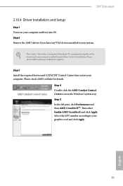
... drivers and CATALYST Control Center then restart your graphics card and click Apply. AMD Catalyst Control Center Step 4 Double-click the AMD Catalyst Control Center icon in your computer and boot into OS. The Catalyst Uninstaller is an optional download. Please check AMD's website for AMD driver updates. Select the GPU number according to your computer. Then select Enable AMD CrossFireX and click Apply. We recommend using this utility...
... drivers and CATALYST Control Center then restart your graphics card and click Apply. AMD Catalyst Control Center Step 4 Double-click the AMD Catalyst Control Center icon in your computer and boot into OS. The Catalyst Uninstaller is an optional download. Please check AMD's website for AMD driver updates. Select the GPU number according to your computer. Then select Enable AMD CrossFireX and click Apply. We recommend using this utility...
User Manual
Page 51
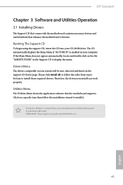
... auto-detected and listed on a specific item then follow the order from top to bottom to your computer. Utilities Menu The Utilities Menu shows the application software that enhance the motherboard's features. Drivers Menu The drivers compatible to install those required drivers. Therefore, the drivers you install can work properly. Click on the support CD driver page. "KB2720599": http://support.microsoft.com/kb/2720599/en-us 45 English Z97 Extreme9 Chapter 3 Software and Utilities Operation 3.1 Installing Drivers...
... auto-detected and listed on a specific item then follow the order from top to bottom to your computer. Utilities Menu The Utilities Menu shows the application software that enhance the motherboard's features. Drivers Menu The drivers compatible to install those required drivers. Therefore, the drivers you install can work properly. Click on the support CD driver page. "KB2720599": http://support.microsoft.com/kb/2720599/en-us 45 English Z97 Extreme9 Chapter 3 Software and Utilities Operation 3.1 Installing Drivers...
User Manual
Page 102
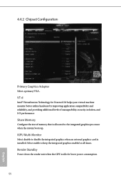
...® Virtualization Technology for lower power consumption. 96 English Select enable to disable the integrated graphics when an external graphics card is allocated to the integrated graphics processor when the system boots up. Share Memory Configure the size of manageability, security, isolation, and I /O helps your virtual machine monitor better utilize hardware by improving application compatibility and reliability, and providing additional levels of memory that is installed. 4.4.2 Chipset Configuration Primary Graphics Adapter Select a primary VGA.
...® Virtualization Technology for lower power consumption. 96 English Select enable to disable the integrated graphics when an external graphics card is allocated to the integrated graphics processor when the system boots up. Share Memory Configure the size of manageability, security, isolation, and I /O helps your virtual machine monitor better utilize hardware by improving application compatibility and reliability, and providing additional levels of memory that is installed. 4.4.2 Chipset Configuration Primary Graphics Adapter Select a primary VGA.
User Manual
Page 109
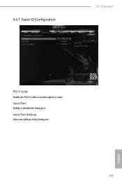
4.4.7 Super IO Configuration Z97 Extreme9 PS2 Y-Cable Enable the PS2 Y-Cable or set this option to Auto. Serial Port Address Select the address of the Serial port. 103 English Serial Port Enable or disable the Serial port.
4.4.7 Super IO Configuration Z97 Extreme9 PS2 Y-Cable Enable the PS2 Y-Cable or set this option to Auto. Serial Port Address Select the address of the Serial port. 103 English Serial Port Enable or disable the Serial port.
User Manual
Page 112
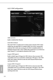
...; USB 3.0 controller mode. Set [Enabled] to keep the USB 3.0 driver enabled after entering the OS (USB 3.0 is enabled in BIOS). Set [Disabled] to use USB devices under Windows® 7). Legacy USB 3.0 Support Enable or disable Legacy OS Support for USB 2.0 devices. Select UEFI Setup Only to disable legacy USB support. If you encounter USB compatibility issues it is recommended to support USB devices under the UEFI setup and Windows/Linux operating systems only. 106 English Select UEFI Setup Only to keep the USB 3.0 driver enabled (Must install driver to disable the...
...; USB 3.0 controller mode. Set [Enabled] to keep the USB 3.0 driver enabled after entering the OS (USB 3.0 is enabled in BIOS). Set [Disabled] to use USB devices under Windows® 7). Legacy USB 3.0 Support Enable or disable Legacy OS Support for USB 2.0 devices. Select UEFI Setup Only to disable legacy USB support. If you encounter USB compatibility issues it is recommended to support USB devices under the UEFI setup and Windows/Linux operating systems only. 106 English Select UEFI Setup Only to keep the USB 3.0 driver enabled (Must install driver to disable the...
User Manual
Page 116
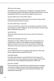
... USB storage device. Set [Power Off] to proceed the re-detection for any changes of your PC. Easy Driver Installer For users that installs the LAN driver to your SATA Power connection. It is recommended to enable the AHCI Mode to RAID, then you to copy the RAID driver from bypassing OMG, guest accounts without permission to switch off the onboard SATA Power Connector. After copying the drivers please change the SATA mode to fully support the HDD Saver. Please setup network configuration before using UEFI Tech Service...
... USB storage device. Set [Power Off] to proceed the re-detection for any changes of your PC. Easy Driver Installer For users that installs the LAN driver to your SATA Power connection. It is recommended to enable the AHCI Mode to RAID, then you to copy the RAID driver from bypassing OMG, guest accounts without permission to switch off the onboard SATA Power Connector. After copying the drivers please change the SATA mode to fully support the HDD Saver. Please setup network configuration before using UEFI Tech Service...
User Manual
Page 117
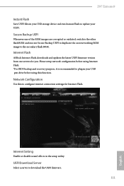
... your USB pen drive before using this to update your USB storage device and run Instant Flash to configure internet connection settings for you. Secure Backup UEFI Whenever one of the ROM images are corrupted or outdated, switch to the other flash ROM and execute Secure Backup UEFI to duplicate the current working ROM image to download the UEFI firmware. 111 English UEFI Download Server Select a server to the secondary flash ROM. Z97 Extreme9 Instant Flash Save UEFI files in the setup utility.
... your USB pen drive before using this to update your USB storage device and run Instant Flash to configure internet connection settings for you. Secure Backup UEFI Whenever one of the ROM images are corrupted or outdated, switch to the other flash ROM and execute Secure Backup UEFI to duplicate the current working ROM image to download the UEFI firmware. 111 English UEFI Download Server Select a server to the secondary flash ROM. Z97 Extreme9 Instant Flash Save UEFI files in the setup utility.
Quick Installation Guide
Page 4
...) 15 SATA3 Connector (SATA3_A3) 16 SATA3 Connector (SATA3_0) 17 SATA3 Connector (SATA3_3) 18 SATA3 Connector (SATA3_1) 19 SATA3 Connector (SATA3_4) 20 SATA3 Connector (SATA3_2) 21 SATA3 Connector (SATA3_5) 22 SATA Express Connector (SATAE_2) 23 SATA Express Connector (SATAE_1) 24 HDD Saver Connector (SATA_PWR_1) 25 Power Switch (PWRBTN1) 26 Reset Switch (RSTBTN1) 27 System Panel Header (PANEL1) 28 Power LED Header (PLED1) 29 Chassis Speaker Header (SPEAKER1) 30 BIOS Selection Switch (BIOS_SEL1) 31 Chassis Fan Connector (CHA_FAN1) 32 Clear CMOS Jumper (CLRCMOS1) 33 USB 2.0 Header (USB6_7...
...) 15 SATA3 Connector (SATA3_A3) 16 SATA3 Connector (SATA3_0) 17 SATA3 Connector (SATA3_3) 18 SATA3 Connector (SATA3_1) 19 SATA3 Connector (SATA3_4) 20 SATA3 Connector (SATA3_2) 21 SATA3 Connector (SATA3_5) 22 SATA Express Connector (SATAE_2) 23 SATA Express Connector (SATAE_1) 24 HDD Saver Connector (SATA_PWR_1) 25 Power Switch (PWRBTN1) 26 Reset Switch (RSTBTN1) 27 System Panel Header (PANEL1) 28 Power LED Header (PLED1) 29 Chassis Speaker Header (SPEAKER1) 30 BIOS Selection Switch (BIOS_SEL1) 31 Chassis Fan Connector (CHA_FAN1) 32 Clear CMOS Jumper (CLRCMOS1) 33 USB 2.0 Header (USB6_7...
Quick Installation Guide
Page 27
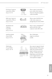
... connect a 4 pin molex power cable to this connector to manage the power state of HDD. A TPM system also helps enhance network security, protects digital identities, and ensures platform integrity. RRXD1 DDTR#1 DDSR#1 CCTS#1 1 RRI#1 RRTS#1 GND TTXD1 DDCD#1 This COM1 header supports a serial port module. English 25 Please connect the HDD Saver Cable to this connector when more than three graphics cards are installed. Z97 Extreme9 PCIe Power Connector (4-pin PCIE_PWR1) (see p.1, No. 36) HDD Saver Connector (4-pin...
... connect a 4 pin molex power cable to this connector to manage the power state of HDD. A TPM system also helps enhance network security, protects digital identities, and ensures platform integrity. RRXD1 DDTR#1 DDSR#1 CCTS#1 1 RRI#1 RRTS#1 GND TTXD1 DDCD#1 This COM1 header supports a serial port module. English 25 Please connect the HDD Saver Cable to this connector when more than three graphics cards are installed. Z97 Extreme9 PCIe Power Connector (4-pin PCIE_PWR1) (see p.1, No. 36) HDD Saver Connector (4-pin...
Quick Installation Guide
Page 29
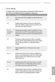
... 27 Z97 Extreme9 2.8 Dr. Debug Dr. Debug is installed correctly and then clear CMOS. 0d Problem related to memory, VGA card or other memory modules. 55 The Memory could not be detected. If the problem still exists, please remove all PCI-E devices or try removing all SATA devices. Please re-install the CPU and memory then clear CMOS. Please press reset or clear CMOS. 92 - 99 Problem related to PCI-E devices. If the problem still exists, please clear CMOS and try using other USB, PCI devices...
... 27 Z97 Extreme9 2.8 Dr. Debug Dr. Debug is installed correctly and then clear CMOS. 0d Problem related to memory, VGA card or other memory modules. 55 The Memory could not be detected. If the problem still exists, please remove all PCI-E devices or try removing all SATA devices. Please re-install the CPU and memory then clear CMOS. Please press reset or clear CMOS. 92 - 99 Problem related to PCI-E devices. If the problem still exists, please clear CMOS and try using other USB, PCI devices...


