User Manual
Page 7
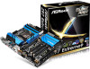
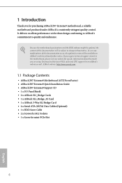
.... It delivers excellent performance with robust design conforming to ASRock's commitment to quality and endurance. ASRock website http://www.asrock.com. 1.1 Package Contents • ASRock Z97 Extreme9 Motherboard (ATX Form Factor) • ASRock Z97 Extreme9 Quick Installation Guide • ASRock Z97 Extreme9 Support CD • 1 x I/O Panel Shield • 2 x ASRock SLI_Bridge Cards • 1 x ASRock SLI_Bridge_3S Card • 1 x ASRock 3-Way SLI Bridge Card • 4 x Serial ATA (SATA) Data...
.... It delivers excellent performance with robust design conforming to ASRock's commitment to quality and endurance. ASRock website http://www.asrock.com. 1.1 Package Contents • ASRock Z97 Extreme9 Motherboard (ATX Form Factor) • ASRock Z97 Extreme9 Quick Installation Guide • ASRock Z97 Extreme9 Support CD • 1 x I/O Panel Shield • 2 x ASRock SLI_Bridge Cards • 1 x ASRock SLI_Bridge_3S Card • 1 x ASRock 3-Way SLI Bridge Card • 4 x Serial ATA (SATA) Data...

User Manual
Page 8
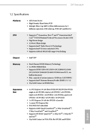
... dual at x8 (PCIE1) / x8 (PCIE2) / x16 (PCIE4); triple at x16 (PCIE1) / x16 (PCIE4); 1.2 Specifications Platform CPU • ATX Form Factor • High Density Glass Fabric PCB • Multiple Filter Cap (MFC) (Filter different noise by 3 different capacitors: DIP solid cap, POSCAP...• Supports Intel® Turbo Boost 2.0 Technology • Supports Intel® K-Series unlocked CPUs • Supports ASRock BCLK Full-range Overclocking Chipset • Intel® Z97 Memory • Dual Channel DDR3 Memory Technology • 4 x DDR3 DIMM Slots • Supports DDR3 3200+(OC)/...
... dual at x8 (PCIE1) / x8 (PCIE2) / x16 (PCIE4); triple at x16 (PCIE1) / x16 (PCIE4); 1.2 Specifications Platform CPU • ATX Form Factor • High Density Glass Fabric PCB • Multiple Filter Cap (MFC) (Filter different noise by 3 different capacitors: DIP solid cap, POSCAP...• Supports Intel® Turbo Boost 2.0 Technology • Supports Intel® K-Series unlocked CPUs • Supports ASRock BCLK Full-range Overclocking Chipset • Intel® Z97 Memory • Dual Channel DDR3 Memory Technology • 4 x DDR3 DIMM Slots • Supports DDR3 3200+(OC)/...
User Manual
Page 11
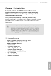
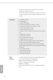
...Z97 Extreme9 • 1 x Ultra M.2 Socket (M2_1), supports M.2 PCI Express module up to Gen2 x2 (10 Gb/s) Connector • 1 x COM Port Header • 1 x TPM Header • 1 x Power LED Header • 2 x CPU Fan Connectors (1 x 4-pin, 1 x 3-pin) • 3 x Chassis Fan Connectors (1 x 4-pin, 2 x 3-pin) • 1 x Power Fan Connector (3-pin) • 1 x 24 pin ATX... 4 USB 2.0 ports) (Supports ESD Protection (ASRock Full Spike Protection)) • 2 x USB 3.0 Headers (Support 4 USB 3.0 ports) (ASMedia ASM1074 hub) (Supports ESD Protection (ASRock Full Spike Protection)) • 1 x Dr....
...Z97 Extreme9 • 1 x Ultra M.2 Socket (M2_1), supports M.2 PCI Express module up to Gen2 x2 (10 Gb/s) Connector • 1 x COM Port Header • 1 x TPM Header • 1 x Power LED Header • 2 x CPU Fan Connectors (1 x 4-pin, 1 x 3-pin) • 3 x Chassis Fan Connectors (1 x 4-pin, 2 x 3-pin) • 1 x Power Fan Connector (3-pin) • 1 x 24 pin ATX... 4 USB 2.0 ports) (Supports ESD Protection (ASRock Full Spike Protection)) • 2 x USB 3.0 Headers (Support 4 USB 3.0 ports) (ASMedia ASM1074 hub) (Supports ESD Protection (ASRock Full Spike Protection)) • 1 x Dr....

User Manual
Page 14
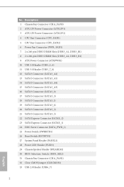
... Fan Connector (CPU_FAN1) 5 CPU Fan Connector (CPU_FAN2) 6 Power Fan Connector (PWR_FAN1) 7 2 x 240-pin DDR3 DIMM Slots (DDR3_A1, DDR3_B1) 8 2 x 240-pin DDR3 DIMM Slots (DDR3_A2, DDR3_B2) 9 ATX Power Connector (ATXPWR1) 10 USB 3.0 Header (USB3_5_6) 11 USB 3.0 Header (USB3_7_8) 12 SATA3 Connector (SATA3_A2) 13 SATA3 Connector (SATA3_A1) 14 SATA3 Connector (SATA3_A4) 15 SATA3...
... Fan Connector (CPU_FAN1) 5 CPU Fan Connector (CPU_FAN2) 6 Power Fan Connector (PWR_FAN1) 7 2 x 240-pin DDR3 DIMM Slots (DDR3_A1, DDR3_B1) 8 2 x 240-pin DDR3 DIMM Slots (DDR3_A2, DDR3_B2) 9 ATX Power Connector (ATXPWR1) 10 USB 3.0 Header (USB3_5_6) 11 USB 3.0 Header (USB3_7_8) 12 SATA3 Connector (SATA3_A2) 13 SATA3 Connector (SATA3_A1) 14 SATA3 Connector (SATA3_A4) 15 SATA3...
User Manual
Page 18
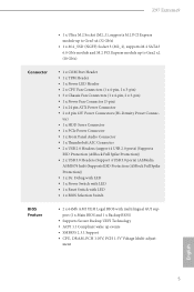
... so may damage the motherboard. 12 English Before you install motherboard components or change any components, place them on a carpet. Chapter 2 Installation This is an ATX form factor motherboard. Doing so may cause physical injuries and damages to motherboard components. • In order to avoid damage from static electricity to the...
... so may damage the motherboard. 12 English Before you install motherboard components or change any components, place them on a carpet. Chapter 2 Installation This is an ATX form factor motherboard. Doing so may cause physical injuries and damages to motherboard components. • In order to avoid damage from static electricity to the...
User Manual
Page 30
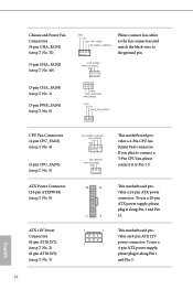
...p.7, No. 6) GND FAN_VOLTAGE FAN_SPEED CPU Fan Connectors (4-pin CPU_FAN1) (see p.7, No. 4) (3-pin CPU_FAN2) (see p.7, No. 5) ATX Power Connector (24-pin ATXPWR1) (see p.7, No. 9) ATX 12V Power Connectors (8-pin ATX12V1) (see p.7, No. 2) (8-pin ATX12V2) (see p.7, No. 40) GND +12V CHA_FAN_SPEED FAN_SPEED_CONTROL Please ... match the black wire to Pin 1-3. 12 24 1 13 8 5 4 1 This motherboard provides a 24-pin ATX power connector. This motherboard provides an 8-pin ATX 12V power connector. Chassis and Power Fan Connectors (4-pin CHA_FAN1) (see p.7, No. 31) (3-pin CHA_FAN2) (see...
...p.7, No. 6) GND FAN_VOLTAGE FAN_SPEED CPU Fan Connectors (4-pin CPU_FAN1) (see p.7, No. 4) (3-pin CPU_FAN2) (see p.7, No. 5) ATX Power Connector (24-pin ATXPWR1) (see p.7, No. 9) ATX 12V Power Connectors (8-pin ATX12V1) (see p.7, No. 2) (8-pin ATX12V2) (see p.7, No. 40) GND +12V CHA_FAN_SPEED FAN_SPEED_CONTROL Please ... match the black wire to Pin 1-3. 12 24 1 13 8 5 4 1 This motherboard provides a 24-pin ATX power connector. This motherboard provides an 8-pin ATX 12V power connector. Chassis and Power Fan Connectors (4-pin CHA_FAN1) (see p.7, No. 31) (3-pin CHA_FAN2) (see...
Quick Installation Guide
Page 4
... Fan Connector (CPU_FAN1) 5 CPU Fan Connector (CPU_FAN2) 6 Power Fan Connector (PWR_FAN1) 7 2 x 240-pin DDR3 DIMM Slots (DDR3_A1, DDR3_B1) 8 2 x 240-pin DDR3 DIMM Slots (DDR3_A2, DDR3_B2) 9 ATX Power Connector (ATXPWR1) 10 USB 3.0 Header (USB3_5_6) 11 USB 3.0 Header (USB3_7_8) 12 SATA3 Connector (SATA3_A2) 13 SATA3 Connector (SATA3_A1) 14 SATA3 Connector (SATA3_A4) 15 SATA3...
... Fan Connector (CPU_FAN1) 5 CPU Fan Connector (CPU_FAN2) 6 Power Fan Connector (PWR_FAN1) 7 2 x 240-pin DDR3 DIMM Slots (DDR3_A1, DDR3_B1) 8 2 x 240-pin DDR3 DIMM Slots (DDR3_A2, DDR3_B2) 9 ATX Power Connector (ATXPWR1) 10 USB 3.0 Header (USB3_5_6) 11 USB 3.0 Header (USB3_7_8) 12 SATA3 Connector (SATA3_A2) 13 SATA3 Connector (SATA3_A1) 14 SATA3 Connector (SATA3_A4) 15 SATA3...
Quick Installation Guide
Page 8
ASRock website http://www.asrock.com. 1.1 Package Contents • ASRock Z97 Extreme9 Motherboard (ATX Form Factor) • ASRock Z97 Extreme9 Quick Installation Guide • ASRock Z97 Extreme9 Support CD • 1 x I/O Panel Shield • 2 x ASRock SLI_Bridge Cards • 1 x ASRock SLI_Bridge_3S Card • 1 x ASRock 3-Way SLI Bridge Card • 4 x Serial ATA (SATA) Data Cables (Optional) • 1 x HDD Saver Cable • 2 x Screws for M.2 Sockets • 1 x Screw for purchasing ASRock Z97 Extreme9 motherboard...
ASRock website http://www.asrock.com. 1.1 Package Contents • ASRock Z97 Extreme9 Motherboard (ATX Form Factor) • ASRock Z97 Extreme9 Quick Installation Guide • ASRock Z97 Extreme9 Support CD • 1 x I/O Panel Shield • 2 x ASRock SLI_Bridge Cards • 1 x ASRock SLI_Bridge_3S Card • 1 x ASRock 3-Way SLI Bridge Card • 4 x Serial ATA (SATA) Data Cables (Optional) • 1 x HDD Saver Cable • 2 x Screws for M.2 Sockets • 1 x Screw for purchasing ASRock Z97 Extreme9 motherboard...
Quick Installation Guide
Page 9
quad at x8 (PCIE1) / x8 (PCIE2) / x16 (PCIE4); Z97 Extreme9 1.2 Specifications Platform CPU • ATX Form Factor • High Density Glass Fabric PCB • Multiple Filter Cap (MFC) (Filter different noise by 3 different capacitors: DIP solid cap...Power Phase design • Supports Intel® Turbo Boost 2.0 Technology • Supports Intel® K-Series unlocked CPUs • Supports ASRock BCLK Full-range Overclocking Chipset • Intel® Z97 Memory • Dual Channel DDR3 Memory Technology • 4 x DDR3 DIMM Slots • Supports DDR3 3200+(OC)/2933+(OC)/2800(...
quad at x8 (PCIE1) / x8 (PCIE2) / x16 (PCIE4); Z97 Extreme9 1.2 Specifications Platform CPU • ATX Form Factor • High Density Glass Fabric PCB • Multiple Filter Cap (MFC) (Filter different noise by 3 different capacitors: DIP solid cap...Power Phase design • Supports Intel® Turbo Boost 2.0 Technology • Supports Intel® K-Series unlocked CPUs • Supports ASRock BCLK Full-range Overclocking Chipset • Intel® Z97 Memory • Dual Channel DDR3 Memory Technology • 4 x DDR3 DIMM Slots • Supports DDR3 3200+(OC)/2933+(OC)/2800(...
Quick Installation Guide
Page 12
...8226; 1 x Thunderbolt AIC Connector • 2 x USB 2.0 Headers (support 4 USB 2.0 ports) (Supports ESD Protection (ASRock Full Spike Protection)) • 2 x USB 3.0 Headers (Support 4 USB 3.0 ports) (ASMedia ASM1074 hub) (Supports ESD Protection (ASRock Full Spike Protection)) • 1 x Dr. Debug with LED • 1 x Power Switch with LED • 1...CPU Fan Connectors (1 x 4-pin, 1 x 3-pin) • 3 x Chassis Fan Connectors (1 x 4-pin, 2 x 3-pin) • 1 x Power Fan Connector (3-pin) • 1 x 24 pin ATX Power Connector • 2 x 8 pin 12V Power Connectors (Hi-Density Power Connec-
...8226; 1 x Thunderbolt AIC Connector • 2 x USB 2.0 Headers (support 4 USB 2.0 ports) (Supports ESD Protection (ASRock Full Spike Protection)) • 2 x USB 3.0 Headers (Support 4 USB 3.0 ports) (ASMedia ASM1074 hub) (Supports ESD Protection (ASRock Full Spike Protection)) • 1 x Dr. Debug with LED • 1 x Power Switch with LED • 1...CPU Fan Connectors (1 x 4-pin, 1 x 3-pin) • 3 x Chassis Fan Connectors (1 x 4-pin, 2 x 3-pin) • 1 x Power Fan Connector (3-pin) • 1 x 24 pin ATX Power Connector • 2 x 8 pin 12V Power Connectors (Hi-Density Power Connec-

Quick Installation Guide
Page 14
... following precautions before you uninstall any motherboard settings. • Make sure to the chassis, please do not overtighten the screws! Chapter 2 Installation This is an ATX form factor motherboard.
... following precautions before you uninstall any motherboard settings. • Make sure to the chassis, please do not overtighten the screws! Chapter 2 Installation This is an ATX form factor motherboard.

Quick Installation Guide
Page 26
...to the fan connectors and match the black wire to Pin 1-3. 12 24 1 13 8 5 4 1 This motherboard provides a 24-pin ATX power connector. To use a 4-pin ATX power supply, please plug it along Pin 1 and Pin 5. English If you plan to connect a 3-Pin CPU fan, please connect it... to the ground pin. This motherboard provides an 8-pin ATX 12V power connector. Chassis and Power Fan Connectors (4-pin CHA_FAN1) (see p.1, No. 31) (3-pin CHA_FAN2) (see p.1, No. 3) 24 FAN_SPEED_CONTROL FAN_SPEED +12V...
...to the fan connectors and match the black wire to Pin 1-3. 12 24 1 13 8 5 4 1 This motherboard provides a 24-pin ATX power connector. To use a 4-pin ATX power supply, please plug it along Pin 1 and Pin 5. English If you plan to connect a 3-Pin CPU fan, please connect it... to the ground pin. This motherboard provides an 8-pin ATX 12V power connector. Chassis and Power Fan Connectors (4-pin CHA_FAN1) (see p.1, No. 31) (3-pin CHA_FAN2) (see p.1, No. 3) 24 FAN_SPEED_CONTROL FAN_SPEED +12V...
Quick Installation Guide
Page 144
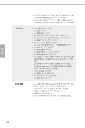
... x 3 ϐϯʣ • 1 x 24 ϐϯ ATX 2 x 8 ϐϯ 12V 1 x HDD 1 x PCIe 1 x 1 x Thunderbolt AIC 2 x USB 2.0 ϔομʔʢ4 ݸͷ USB 2.0 ESD ASRock 2 x USB 3.0 ϔομʔʢ4 ݸͷ... USB 3.0 ASMedia ASM1074 ESD ASRock 1 x Dr. DebugɺLED ͖ • 1 x LED ͖ • ...
... x 3 ϐϯʣ • 1 x 24 ϐϯ ATX 2 x 8 ϐϯ 12V 1 x HDD 1 x PCIe 1 x 1 x Thunderbolt AIC 2 x USB 2.0 ϔομʔʢ4 ݸͷ USB 2.0 ESD ASRock 2 x USB 3.0 ϔομʔʢ4 ݸͷ... USB 3.0 ASMedia ASM1074 ESD ASRock 1 x Dr. DebugɺLED ͖ • 1 x LED ͖ • ...