
User Manual
Page 2
... possibility of such damages arising from any defect or error in the manual or product. With respect to infringe. ASRock assumes no event shall ASRock, its directors, officers, employees, or agents be constructed as a commitment by the California Legislature. Operation is subject...for any kind, either expressed or implied, including but not limited to change without written consent of ASRock Inc. Products and corporate names appearing in this motherboard contains Perchlorate, a toxic substance controlled in advance. When you discard the Lithium battery in California, USA...
... possibility of such damages arising from any defect or error in the manual or product. With respect to infringe. ASRock assumes no event shall ASRock, its directors, officers, employees, or agents be constructed as a commitment by the California Legislature. Operation is subject...for any kind, either expressed or implied, including but not limited to change without written consent of ASRock Inc. Products and corporate names appearing in this motherboard contains Perchlorate, a toxic substance controlled in advance. When you discard the Lithium battery in California, USA...

User Manual
Page 3
Contents 1 Introduction 5 1.1 Package Contents 5 1.2 Specifications 6 1.3 Two SLITM Graphics Card Support List 11 1.4 Two CrossFireXTM Graphics Card Support List 12 1.5 Motherboard Layout 13 1.6 I/O Panel 14 2 Installation 16 2.1 Screw Holes 16 2.2 Pre-installation Precautions 16 2.3 CPU Installation 17 2.4 Installation of Heatsink and CPU fan 19 2.5 Installation of ...
Contents 1 Introduction 5 1.1 Package Contents 5 1.2 Specifications 6 1.3 Two SLITM Graphics Card Support List 11 1.4 Two CrossFireXTM Graphics Card Support List 12 1.5 Motherboard Layout 13 1.6 I/O Panel 14 2 Installation 16 2.1 Screw Holes 16 2.2 Pre-installation Precautions 16 2.3 CPU Installation 17 2.4 Installation of Heatsink and CPU fan 19 2.5 Installation of ...
User Manual
Page 5
... visit our website for a 3.5-in , 30.5 cm x 24.4 cm) ASRock X58 Extreme3 Quick Installation Guide ASRock X58 Extreme3 Support CD 1 x 80-conductor Ultra ATA 66/100/133 IDE Ribbon Cable 1 x Ribbon Cable for specific information about the model you for purchasing ASRock X58 Extreme3 motherboard, a reliable motherboard produced under ASRock's consistently stringent quality control. You may find the latest VGA cards and...
... visit our website for a 3.5-in , 30.5 cm x 24.4 cm) ASRock X58 Extreme3 Quick Installation Guide ASRock X58 Extreme3 Support CD 1 x 80-conductor Ultra ATA 66/100/133 IDE Ribbon Cable 1 x Ribbon Cable for specific information about the model you for purchasing ASRock X58 Extreme3 motherboard, a reliable motherboard produced under ASRock's consistently stringent quality control. You may find the latest VGA cards and...
User Manual
Page 9
... operation procedures of "Hyper Threading Technology", please check page 62. 2. About the setting of ASRock OC Tuner. This motherboard supports Untied Overclocking Technology. For audio output, this motherboard supports both stereo and mono modes. It is a user-friendly ASRock overclocking tool which allows you can update your BIOS only in Flash ROM. Please visit...
... operation procedures of "Hyper Threading Technology", please check page 62. 2. About the setting of ASRock OC Tuner. This motherboard supports Untied Overclocking Technology. For audio output, this motherboard supports both stereo and mono modes. It is a user-friendly ASRock overclocking tool which allows you can update your BIOS only in Flash ROM. Please visit...
User Manual
Page 10
...settings and share with others. Before you install the PC system. 13. EuP, stands for Energy Using Product, was a provision regulated by ASRock, provides a convenient way for the completed system. According to spray thermal grease between the CPU and the heatsink when you resume the system...can only be under the operating system and simplifies the complicated recording process of the completed system shall be shared and worked on the motherboard functions properly and unplug the power cord, then plug it back again. To improve heat dissipation, remember to Intel's suggestion, the...
...settings and share with others. Before you install the PC system. 13. EuP, stands for Energy Using Product, was a provision regulated by ASRock, provides a convenient way for the completed system. According to spray thermal grease between the CPU and the heatsink when you resume the system...can only be under the operating system and simplifies the complicated recording process of the completed system shall be shared and worked on the motherboard functions properly and unplug the power cord, then plug it back again. To improve heat dissipation, remember to Intel's suggestion, the...
User Manual
Page 13
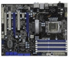
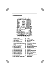
... DDR3 DIMM Slots 33 Infrared Module Header (IR1) (Triple Channel: DDR3_A2, DDR3_B2, DDR3_C2 34 PCI Express x16 Slot (PCIE4, White) ; 1.5 Motherboard Layout 123 45 6 7 24.4cm (9.6 in) Six-Core CPU Ready 1 PS2_USB_PWR1 ATX12V1 PWR_FAN1 CHA_FAN2 8 CPU_FAN1 PS2 Mouse PS2 Keyboard Clr CMOS 30...CODEC Super I/O CI1 1 IR1 1 HDMI_SPDIF1 1 FLOPPY1 NEC USB 3.0 SATA3 6Gb/s IDE1 PCIE1 QPI 6.4GT/s PCIE2 PCI Express 2.0 PCI1 X58 Extreme3 8Mb BIOS 1394a CMOS Battery CLRCMOS1 1 PCIE3 ErP/EuP Ready PCI2 VIA VT6308S Intel ICH10R RoHS PCIE4 COM1 1 1 TPM1 FRONT_1394 CHA_FAN1 1...
... DDR3 DIMM Slots 33 Infrared Module Header (IR1) (Triple Channel: DDR3_A2, DDR3_B2, DDR3_C2 34 PCI Express x16 Slot (PCIE4, White) ; 1.5 Motherboard Layout 123 45 6 7 24.4cm (9.6 in) Six-Core CPU Ready 1 PS2_USB_PWR1 ATX12V1 PWR_FAN1 CHA_FAN2 8 CPU_FAN1 PS2 Mouse PS2 Keyboard Clr CMOS 30...CODEC Super I/O CI1 1 IR1 1 HDMI_SPDIF1 1 FLOPPY1 NEC USB 3.0 SATA3 6Gb/s IDE1 PCIE1 QPI 6.4GT/s PCIE2 PCI Express 2.0 PCI1 X58 Extreme3 8Mb BIOS 1394a CMOS Battery CLRCMOS1 1 PCIE3 ErP/EuP Ready PCI2 VIA VT6308S Intel ICH10R RoHS PCIE4 COM1 1 1 TPM1 FRONT_1394 CHA_FAN1 1...

User Manual
Page 16
... damage to unplug the power cord before installing or removing the motherboard. Before you uninstall any motherboard settings. 1. Do not over-tighten the screws! Hold components by circles to secure the motherboard to ensure that the motherboard fits into the holes indicated by the edges and do so ... ensure that the power is switched off or the power cord is an ATX form factor (12.0" x 9.6", 30.5 x 24.4 cm) motherboard. Doing so may cause physical injuries to motherboard components. 2.1 Screw Holes Place screws into it on the carpet or the like. Whenever you install the...
... damage to unplug the power cord before installing or removing the motherboard. Before you uninstall any motherboard settings. 1. Do not over-tighten the screws! Hold components by circles to secure the motherboard to ensure that the motherboard fits into the holes indicated by the edges and do so ... ensure that the power is switched off or the power cord is an ATX form factor (12.0" x 9.6", 30.5 x 24.4 cm) motherboard. Doing so may cause physical injuries to motherboard components. 2.1 Screw Holes Place screws into it on the carpet or the like. Whenever you install the...
User Manual
Page 17
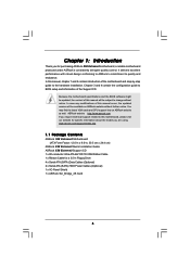
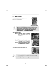
... degrees. 2.3 CPU Installation For the installation of Intel 1366-Pin CPU, please follow the steps below. Otherwise, the CPU will be placed if returning the motherboard for after service. 17 This cap must be seriously damaged. Step 2. Rotate the load lever to clear retention tab. Rotate the load plate to handle...
... degrees. 2.3 CPU Installation For the installation of Intel 1366-Pin CPU, please follow the steps below. Otherwise, the CPU will be placed if returning the motherboard for after service. 17 This cap must be seriously damaged. Step 2. Rotate the load lever to clear retention tab. Rotate the load plate to handle...

User Manual
Page 19
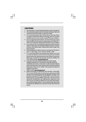
...them clockwise, the heatsink cannot be secured on the socket surface. Repeat with the motherboard throughholes. For proper installation, please kindly refer to the instruction manuals of IHS on the motherboard. Ensure fan cables are securely fastened and in good contact with Intel 1366-Pin ... spray thermal interface material between the CPU and the heatsink to improve heat dissipation. 2.4 Installation of CPU Fan and Heatsink This motherboard is an example to illustrate the installation of the heatsink for 1366-Pin CPU. Step 6. Step 1. Step 3. Ensure that supports Intel ...
...them clockwise, the heatsink cannot be secured on the socket surface. Repeat with the motherboard throughholes. For proper installation, please kindly refer to the instruction manuals of IHS on the motherboard. Ensure fan cables are securely fastened and in good contact with Intel 1366-Pin ... spray thermal interface material between the CPU and the heatsink to improve heat dissipation. 2.4 Installation of CPU Fan and Heatsink This motherboard is an example to illustrate the installation of the heatsink for 1366-Pin CPU. Step 6. Step 1. Step 3. Ensure that supports Intel ...
User Manual
Page 20
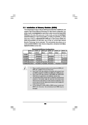
... Channel B and Channel C. Populated 5 DIMMs Populated Populated Populated Populated - The system maps the total size of Memory Modules (DIMM) This motherboard provides six 240-pin DDR3 (Double Data Rate 3) DIMM slots, and supports Triple Channel Memory Technology. It is not allowed to Intel®...DIMMs for triple channel configuration, and please install identical DDR3 DIMMs in Triple Channel (DDR3_A2, DDR3_B2 and DDR3_C2; otherwise, this motherboard and DIMM may install varying memory sizes in the slots of the same color. In other words, you always need to install...
... Channel B and Channel C. Populated 5 DIMMs Populated Populated Populated Populated - The system maps the total size of Memory Modules (DIMM) This motherboard provides six 240-pin DDR3 (Double Data Rate 3) DIMM slots, and supports Triple Channel Memory Technology. It is not allowed to Intel®...DIMMs for triple channel configuration, and please install identical DDR3 DIMMs in Triple Channel (DDR3_A2, DDR3_B2 and DDR3_C2; otherwise, this motherboard and DIMM may install varying memory sizes in the slots of the same color. In other words, you always need to install...

User Manual
Page 21
... the DIMM into the slot at both ends fully snap back in one correct orientation. Step 3. Step 1. Step 2. Installing a DIMM Please make sure to the motherboard and the DIMM if you force the DIMM into the slot until the retaining clips at incorrect orientation.
... the DIMM into the slot at both ends fully snap back in one correct orientation. Step 3. Step 1. Step 2. Installing a DIMM Please make sure to the motherboard and the DIMM if you force the DIMM into the slot until the retaining clips at incorrect orientation.

User Manual
Page 22
...Express x1 lane width cards, such as Gigabit LAN card, SATA2 card, etc. Remove the system unit cover (if your motherboard is used for the card before you intend to motherboard chassis fan connector (CHA_FAN1 or CHA_FAN2) when using multiple graphics cards for PCI Express cards with screws. Replace the system ... x1 slot; White) is used for better thermal environment. In CrossFireXTM mode or SLITM mode, please install PCI Express x16 graphics cards on this motherboard. Step 2. Step 4. Fasten the card to install expansion cards that you start the installation. Step 6.
...Express x1 lane width cards, such as Gigabit LAN card, SATA2 card, etc. Remove the system unit cover (if your motherboard is used for the card before you intend to motherboard chassis fan connector (CHA_FAN1 or CHA_FAN2) when using multiple graphics cards for PCI Express cards with screws. Replace the system ... x1 slot; White) is used for better thermal environment. In CrossFireXTM mode or SLITM mode, please install PCI Express x16 graphics cards on this motherboard. Step 2. Step 4. Fasten the card to install expansion cards that you start the installation. Step 6.
User Manual
Page 23
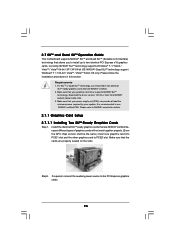
...) can provide at least the minimum power required by your graphics card driver supports NVIDIA® SLITM technology. 2.7 SLITM and Quad SLITM Operation Guide This motherboard supports NVIDIA® SLITM and Quad SLITM (Scalable Link Interface) technology that allows you should have two identical SLITM-ready graphics cards that are NVIDIA...
...) can provide at least the minimum power required by your graphics card driver supports NVIDIA® SLITM technology. 2.7 SLITM and Quad SLITM Operation Guide This motherboard supports NVIDIA® SLITM and Quad SLITM (Scalable Link Interface) technology that allows you should have two identical SLITM-ready graphics cards that are NVIDIA...
User Manual
Page 27
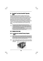
... card to benefit from the CrossFireXTM multi-GPU platform. 2. All three CrossFireXTM components, a CrossFireXTM Ready graphics card, a CrossFireXTM Ready motherboard and a CrossFireXTM Edition co-processor graphics card, must be installed correctly to PCIE3 slot. Combining a range of performance and image quality...ATITM graphics card manuals for ATITM CrossFireXTM driver updates. 1. 2.8 CrossFireXTM and Quad CrossFireXTM Operation Guide This motherboard supports CrossFireXTM and Quad CrossFireXTM feature. In below procedures, we use Radeon HD 3870 as 12-pipe cards while in...
... card to benefit from the CrossFireXTM multi-GPU platform. 2. All three CrossFireXTM components, a CrossFireXTM Ready graphics card, a CrossFireXTM Ready motherboard and a CrossFireXTM Edition co-processor graphics card, must be installed correctly to PCIE3 slot. Combining a range of performance and image quality...ATITM graphics card manuals for ATITM CrossFireXTM driver updates. 1. 2.8 CrossFireXTM and Quad CrossFireXTM Operation Guide This motherboard supports CrossFireXTM and Quad CrossFireXTM feature. In below procedures, we use Radeon HD 3870 as 12-pipe cards while in...

User Manual
Page 28
... the Radeon graphics card on the top of Radeon graphics cards. (CrossFire Bridge is provided with the graphics card you purchase, not bundled with this motherboard. Connect two Radeon graphics cards by installing CrossFire Bridge on CrossFire Bridge Interconnects on PCIE1 slot. (You may use the DVI to D-Sub adapter to...
... the Radeon graphics card on the top of Radeon graphics cards. (CrossFire Bridge is provided with the graphics card you purchase, not bundled with this motherboard. Connect two Radeon graphics cards by installing CrossFire Bridge on CrossFire Bridge Interconnects on PCIE1 slot. (You may use the DVI to D-Sub adapter to...
User Manual
Page 32
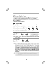
... system parameters to clear the record of Surround Display feature. The illustration shows a 3-pin jumper whose pin1 and pin2 are setup. 2.9 Surround Display Feature This motherboard supports Surround Display upgrade. With the external add-on PCI Express VGA cards, you can easily enjoy the benefits of previous chassis intrusion status. 32
... system parameters to clear the record of Surround Display feature. The illustration shows a 3-pin jumper whose pin1 and pin2 are setup. 2.9 Surround Display Feature This motherboard supports Surround Display upgrade. With the external add-on PCI Express VGA cards, you can easily enjoy the benefits of previous chassis intrusion status. 32

User Manual
Page 33
...SATAII_1_2: see p.13, No. 16) (SATAII_3_4: see p.13, No. 17) (SATAII_5_6: see p.13 No. 14) PIN1 IDE1 connect the blue end to the motherboard connect the black end to the IDE devices 80-conductor ATA 66/100/133 cable Note: Please refer to 3.0 Gb/s data transfer rate. The current...striped side of the cable is plugged into Pin1 side of the connector. The current SATA3 interface allows up to the instruction of the motherboard! Placing jumper caps over these headers and connectors. Do NOT place jumper caps over the headers and connectors will cause permanent damage of ...
...SATAII_1_2: see p.13, No. 16) (SATAII_3_4: see p.13, No. 17) (SATAII_5_6: see p.13 No. 14) PIN1 IDE1 connect the blue end to the motherboard connect the black end to the IDE devices 80-conductor ATA 66/100/133 cable Note: Please refer to 3.0 Gb/s data transfer rate. The current...striped side of the cable is plugged into Pin1 side of the connector. The current SATA3 interface allows up to the instruction of the motherboard! Placing jumper caps over these headers and connectors. Do NOT place jumper caps over the headers and connectors will cause permanent damage of ...

User Manual
Page 34
... 2.0 header can securely store keys, digital certificates, passwords, and data. Please connect the black end of SATA power cable to the power connector on this motherboard. This header supports an optional wireless transmitting and receiving infrared module. 34 Serial ATA (SATA) Data Cable (Optional) Serial ATA (SATA) Power Cable (Optional) connect... NC Either end of the SATA data cable can be connected to the SATA / SATAII / SATA3 hard disk or the SATAII / SATA3 connector on this motherboard.
... 2.0 header can securely store keys, digital certificates, passwords, and data. Please connect the black end of SATA power cable to the power connector on this motherboard. This header supports an optional wireless transmitting and receiving infrared module. 34 Serial ATA (SATA) Data Cable (Optional) Serial ATA (SATA) Power Cable (Optional) connect... NC Either end of the SATA data cable can be connected to the SATA / SATAII / SATA3 hard disk or the SATAII / SATA3 connector on this motherboard.

User Manual
Page 35
... front panel audio cable that detects if the chassis cover has been removed. Front Panel Audio Header (9-pin HD_AUDIO1) (see p.13 No. 43) CD1 This motherboard supports CASE OPEN detection feature that allows convenient connection and control of audio devices. 1. MIC_RET and OUT_RET are for HD audio panel only.
... front panel audio cable that detects if the chassis cover has been removed. Front Panel Audio Header (9-pin HD_AUDIO1) (see p.13 No. 43) CD1 This motherboard supports CASE OPEN detection feature that allows convenient connection and control of audio devices. 1. MIC_RET and OUT_RET are for HD audio panel only.

User Manual
Page 36
... ATX Power Connector (24-pin ATXPWR1) (see p.13, No. 8) 12 24 1 13 Please connect an ATX power supply to the ground pin. Though this motherboard provides 4-Pin CPU fan (Quiet Fan) support, the 3-Pin CPU fan still can work successfully even without the fan speed control function. The LED keeps... CPU fan to the CPU fan connector on when the system is operating. The LED is off in S1 state. The LED is on this motherboard, please connect it to indicate system power status. Power LED Header (3-pin PLED1) (see p.13 No. 20) 1 PLEDPLED+ PLED+ Please connect the chassis power...
... ATX Power Connector (24-pin ATXPWR1) (see p.13, No. 8) 12 24 1 13 Please connect an ATX power supply to the ground pin. Though this motherboard provides 4-Pin CPU fan (Quiet Fan) support, the 3-Pin CPU fan still can work successfully even without the fan speed control function. The LED keeps... CPU fan to the CPU fan connector on when the system is operating. The LED is off in S1 state. The LED is on this motherboard, please connect it to indicate system power status. Power LED Header (3-pin PLED1) (see p.13 No. 20) 1 PLEDPLED+ PLED+ Please connect the chassis power...

