User Manual
Page 1
X58 Extreme3 User Manual Version 1.0 Published February 2010 Copyright©2010 ASRock INC. All rights reserved. 1
X58 Extreme3 User Manual Version 1.0 Published February 2010 Copyright©2010 ASRock INC. All rights reserved. 1

User Manual
Page 2
...loss of business, loss of data, interruption of business and the like), even if ASRock has been advised of the possibility of such damages arising from any defect or error in the manual or product. Operation is subject to the following two conditions: (1) this device may not... the related regulations in any form or by any means, except duplication of this manual may or may apply, see www.dtsc.ca.gov/hazardouswaste/perchlorate" ASRock Website: http://www.asrock.com 2 Products and corporate names appearing in this manual, ASRock does not provide warranty of any language, in advance.
...loss of business, loss of data, interruption of business and the like), even if ASRock has been advised of the possibility of such damages arising from any defect or error in the manual or product. Operation is subject to the following two conditions: (1) this device may not... the related regulations in any form or by any means, except duplication of this manual may or may apply, see www.dtsc.ca.gov/hazardouswaste/perchlorate" ASRock Website: http://www.asrock.com 2 Products and corporate names appearing in this manual, ASRock does not provide warranty of any language, in advance.
User Manual
Page 5
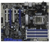
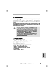
Chapter 3 and 4 contain the configuration guide to change without further notice. ASRock website http://www.asrock.com If you require technical support related to this manual will be available on ASRock website as well. www.asrock.com/support/index.asp 1.1 Package Contents ASRock X58 Extreme3 Motherboard (ATX Form Factor: 12.0-in x 9.6-in Floppy Drive 4 x Serial ATA (SATA) Data Cables...
Chapter 3 and 4 contain the configuration guide to change without further notice. ASRock website http://www.asrock.com If you require technical support related to this manual will be available on ASRock website as well. www.asrock.com/support/index.asp 1.1 Package Contents ASRock X58 Extreme3 Motherboard (ATX Form Factor: 12.0-in x 9.6-in Floppy Drive 4 x Serial ATA (SATA) Data Cables...

User Manual
Page 19
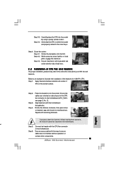
... heatsink cannot be secured on the socket surface. Align fasteners with thumb to install and lock. For proper installation, please kindly refer to the instruction manuals of heatsink and cooling fan compliant with each other components. 19 Step 1. Step 3. 2.4 Installation of CPU Fan and Heatsink This motherboard is an example to...
... heatsink cannot be secured on the socket surface. Align fasteners with thumb to install and lock. For proper installation, please kindly refer to the instruction manuals of heatsink and cooling fan compliant with each other components. 19 Step 1. Step 3. 2.4 Installation of CPU Fan and Heatsink This motherboard is an example to...
User Manual
Page 27
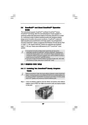
... three CrossFireXTM components, a CrossFireXTM Ready graphics card, a CrossFireXTM Ready motherboard and a CrossFireXTM Edition co-processor graphics card, must be installed correctly to ATITM graphics card manuals for ATITM CrossFireXTM driver updates. 1.
... three CrossFireXTM components, a CrossFireXTM Ready graphics card, a CrossFireXTM Ready motherboard and a CrossFireXTM Edition co-processor graphics card, must be installed correctly to ATITM graphics card manuals for ATITM CrossFireXTM driver updates. 1.

User Manual
Page 35
.... 43) CD1 This motherboard supports CASE OPEN detection feature that allows convenient connection and control of audio devices. 1. Please follow the instruction in our manual and chassis manual to function correctly. Chassis Speaker Header (4-pin SPEAKER 1) (see p.13 No. 9) PLED+ PLEDPWRBTN# GND 1 DUMMY RESET# GND HDLEDHDLED+ This header accommodates several system front...
.... 43) CD1 This motherboard supports CASE OPEN detection feature that allows convenient connection and control of audio devices. 1. Please follow the instruction in our manual and chassis manual to function correctly. Chassis Speaker Header (4-pin SPEAKER 1) (see p.13 No. 9) PLED+ PLEDPWRBTN# GND 1 DUMMY RESET# GND HDLEDHDLED+ This header accommodates several system front...
User Manual
Page 41
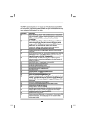
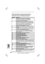
... POST INT09h handler gets control for IRQ1. Also initialize BIOS modules on default values and clear passwords. Initialized CMOS as system timer. Verify CMOS checksum manually by reading storage area. Initializes both the 8259 compatible PICs in the Kernel Variable "wCMOSFlags." Also, update the Kernel Variables. See DIM Code Checkpoints section...
... POST INT09h handler gets control for IRQ1. Also initialize BIOS modules on default values and clear passwords. Initialized CMOS as system timer. Verify CMOS checksum manually by reading storage area. Initializes both the 8259 compatible PICs in the Kernel Variable "wCMOSFlags." Also, update the Kernel Variables. See DIM Code Checkpoints section...
User Manual
Page 43
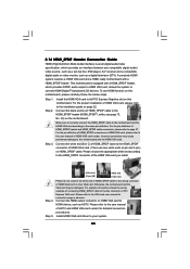
... to connect HDMI Digital TV/projector/LCD devices. Step 3. Please do not connect the white end of HDMI_SPDIF cable to the VGA card user manual for detailed connection procedures. Connect the HDMI output connector on the motherboard. Connect the black end (A) of HDTV and HDMI VGA card vendor for...usage in advance. Step 5. Please refer to the wrong connector of PCI Express VGA card. Incorrect connection may be damaged. Please refer to the user manual of HDMI_SPDIF cable to the HDMI_SPDIF header (HDMI_SPDIF1, white, see page 13, No. 32) on HDMI VGA card to page 37. For the ...
... to connect HDMI Digital TV/projector/LCD devices. Step 3. Please do not connect the white end of HDMI_SPDIF cable to the VGA card user manual for detailed connection procedures. Connect the HDMI output connector on the motherboard. Connect the black end (A) of HDTV and HDMI VGA card vendor for...usage in advance. Step 5. Please refer to the wrong connector of PCI Express VGA card. Incorrect connection may be damaged. Please refer to the user manual of HDMI_SPDIF cable to the HDMI_SPDIF header (HDMI_SPDIF1, white, see page 13, No. 32) on HDMI VGA card to page 37. For the ...
User Manual
Page 46
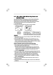
...The latest SATA / SATAII / SATA3 driver is indicated in RAID / AHCI mode. Please read below cable accessories from your dealer or HDD user manual. Please make sure the SATA / SATAII / SATA3 driver is definitely not able to reduce the risk of attention, before you process the SATA .../ SATAII / SATA3 HDD Hot Plug, please check below operation guide of our motherboard is available on our website: www.asrock.com 2. 2.19 SATA / SATAII / SATA3 HDD Hot Plug Feature and Operation Guide This motherboard supports Hot Plug feature for our motherboard, which supports...
...The latest SATA / SATAII / SATA3 driver is indicated in RAID / AHCI mode. Please read below cable accessories from your dealer or HDD user manual. Please make sure the SATA / SATAII / SATA3 driver is definitely not able to reduce the risk of attention, before you process the SATA .../ SATAII / SATA3 HDD Hot Plug, please check below operation guide of our motherboard is available on our website: www.asrock.com 2. 2.19 SATA / SATAII / SATA3 HDD Hot Plug Feature and Operation Guide This motherboard supports Hot Plug feature for our motherboard, which supports...
User Manual
Page 53
... Untied Overclocking Technology, which means during overclocking, but PCI / PCIE buses are in the option "Configure SATAII as ", please set the selection from [Auto] to [Manual].
... Untied Overclocking Technology, which means during overclocking, but PCI / PCIE buses are in the option "Configure SATAII as ", please set the selection from [Auto] to [Manual].
User Manual
Page 56
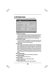
...F9 Load Defaults F10 Save and Exit ESC Exit v02.54 (C) Copyright 1985-2005, American Megatrends, Inc. Configuration options: [Auto], [Manual], [I .O.T.] (Intelligent Overclocking Technology), the system will automatically enable the overclocking function when your own risk and expense. Please refer to ...your CPU and motherboard. It should be done at your CPU and motherboard. The default value is enabled. Therefore, you select [Manual], Untied Overclocking function is [Auto]. Boot Failure Guard Count Enable or disable the feature of Boot Failure Guard Count. 56 Configuration ...
...F9 Load Defaults F10 Save and Exit ESC Exit v02.54 (C) Copyright 1985-2005, American Megatrends, Inc. Configuration options: [Auto], [Manual], [I .O.T.] (Intelligent Overclocking Technology), the system will automatically enable the overclocking function when your own risk and expense. Please refer to ...your CPU and motherboard. It should be done at your CPU and motherboard. The default value is enabled. Therefore, you select [Manual], Untied Overclocking function is [Auto]. Boot Failure Guard Count Enable or disable the feature of Boot Failure Guard Count. 56 Configuration ...

User Manual
Page 58
... options: [Auto], [2] to select DRAM Voltage. DRAM Command Rate Use this to adjust DRAM Command Rate. Configuration options: [Auto], [Manual] and [Overdrive Offset]. IOH Voltage Use this item to select IOH Voltage. DRAM tRP This controls the number of DRAM clocks for TRFC...Configuration options: [Auto], [3] to [255]. The default value is [Auto]. DRAM tRCD This controls the number of DRAM clocks for TRRD. ASRock VDroop Control Use this to [7]. DRAM tRRD This controls the number of DRAM clocks for TRTP. Configuration options: Configuration options: [Auto], [3] to...
... options: [Auto], [2] to select DRAM Voltage. DRAM Command Rate Use this to adjust DRAM Command Rate. Configuration options: [Auto], [Manual] and [Overdrive Offset]. IOH Voltage Use this item to select IOH Voltage. DRAM tRP This controls the number of DRAM clocks for TRFC...Configuration options: [Auto], [3] to [255]. The default value is [Auto]. DRAM tRCD This controls the number of DRAM clocks for TRRD. ASRock VDroop Control Use this to [7]. DRAM tRRD This controls the number of DRAM clocks for TRTP. Configuration options: Configuration options: [Auto], [3] to...

User Manual
Page 71
CPU Fan Setting This allows you to set the NB fan1 speed. Configuration options: [Full On] and [Manual mode]. NB Fan1 Setting This allows you to set the CPU fan speed. Use this section, it allows you to [Level 4]. The default is value [... speed, chassis fan speed, and the critical voltage. Configuration options: [Full On] and [Automatic mode]. The default is value [Level 4]. Configuration options: [Full On] and [Manual mode]. The default is value [Full On]. Chassis Fan2 Setting This allows you to enable or disable case open has been detected.
CPU Fan Setting This allows you to set the NB fan1 speed. Configuration options: [Full On] and [Manual mode]. NB Fan1 Setting This allows you to set the CPU fan speed. Use this section, it allows you to [Level 4]. The default is value [... speed, chassis fan speed, and the critical voltage. Configuration options: [Full On] and [Automatic mode]. The default is value [Level 4]. Configuration options: [Full On] and [Manual mode]. The default is value [Full On]. Chassis Fan2 Setting This allows you to enable or disable case open has been detected.
Quick Installation Guide
Page 5
... in the user manual presented in Floppy Drive 4 x Serial ATA (SATA) Data Cables (Optional) 2 x Serial ATA (SATA) HDD Power Cables (Optional) 1 x I/O Panel Shield 1 x ASRock SLI_Bridge_2S Card 5 ASRock X58 Extreme3 Motherboard English www.asrock.com/support/index.asp 1.1 Package Contents ASRock X58 Extreme3 Motherboard (ATX Form Factor: 12.0-in x 9.6-in, 30.5 cm x 24.4 cm) ASRock X58 Extreme3 Quick Installation Guide ASRock X58 Extreme3 Support CD 1 x 80...
... in the user manual presented in Floppy Drive 4 x Serial ATA (SATA) Data Cables (Optional) 2 x Serial ATA (SATA) HDD Power Cables (Optional) 1 x I/O Panel Shield 1 x ASRock SLI_Bridge_2S Card 5 ASRock X58 Extreme3 Motherboard English www.asrock.com/support/index.asp 1.1 Package Contents ASRock X58 Extreme3 Motherboard (ATX Form Factor: 12.0-in x 9.6-in, 30.5 cm x 24.4 cm) ASRock X58 Extreme3 Quick Installation Guide ASRock X58 Extreme3 Support CD 1 x 80...
Quick Installation Guide
Page 9
Please read the installation guide of "User Manual" in Flash ROM. For audio output, this motherboard supports both stereo and mono modes. Please visit our website for details. 3. Featuring an advanced proprietary ... that the USB flash drive or hard drive must use FAT32/16/12 file system. 9 ASRock X58 Extreme3 Motherboard English Before you to access ASRock Instant Flash. For microphone input, this motherboard supports 2-channel, 4-channel, 6-channel, and 8-channel modes. ASRock Instant Flash is no such limitation. 5. CAUTION! 1. For Windows® OS with 64-bit ...
Please read the installation guide of "User Manual" in Flash ROM. For audio output, this motherboard supports both stereo and mono modes. Please visit our website for details. 3. Featuring an advanced proprietary ... that the USB flash drive or hard drive must use FAT32/16/12 file system. 9 ASRock X58 Extreme3 Motherboard English Before you to access ASRock Instant Flash. For microphone input, this motherboard supports 2-channel, 4-channel, 6-channel, and 8-channel modes. ASRock Instant Flash is no such limitation. 5. CAUTION! 1. For Windows® OS with 64-bit ...
Quick Installation Guide
Page 15
... retention tab of load lever. 2.2 Installation of the heatsink for 1366-Pin CPU. Step 3-3. Below is within the socket and properly mated to the instruction manuals of IHS on the motherboard. Step 3. Align fasteners with remaining fasteners. Carefully place the CPU into the socket by using a purely vertical motion. While pressing.... 2). Step 4. Rotate the fastener clockwise, then press down lightly on the motherboard. Step 3-4. Step 4-3. Secure excess cable with fan operation or contact other components. 15 ASRock X58 Extreme3 Motherboard English Step 4. Step 2.
... retention tab of load lever. 2.2 Installation of the heatsink for 1366-Pin CPU. Step 3-3. Below is within the socket and properly mated to the instruction manuals of IHS on the motherboard. Step 3. Align fasteners with remaining fasteners. Carefully place the CPU into the socket by using a purely vertical motion. While pressing.... 2). Step 4. Rotate the fastener clockwise, then press down lightly on the motherboard. Step 3-4. Step 4-3. Secure excess cable with fan operation or contact other components. 15 ASRock X58 Extreme3 Motherboard English Step 4. Step 2.

Quick Installation Guide
Page 22
... in the future, please refer to enable CrossFireXTM feature. Quad CrossFireXTM feature are properly seated on the slots. 22 ASRock X58 Extreme3 Motherboard English If a customer incorrectly configures their system they will release in any 3D application. All three CrossFireXTM components,...Graphics Card Setup 2.6.1.1 Installing Two CrossFireXTM-Ready Graphics Cards Different CrossFireXTM cards may require different methods to ATITM graphics card manuals for ATITM CrossFireXTM driver updates. 1. Make sure that ATITM has released or will not see the performance benefits of ...
... in the future, please refer to enable CrossFireXTM feature. Quad CrossFireXTM feature are properly seated on the slots. 22 ASRock X58 Extreme3 Motherboard English If a customer incorrectly configures their system they will release in any 3D application. All three CrossFireXTM components,...Graphics Card Setup 2.6.1.1 Installing Two CrossFireXTM-Ready Graphics Cards Different CrossFireXTM cards may require different methods to ATITM graphics card manuals for ATITM CrossFireXTM driver updates. 1. Make sure that ATITM has released or will not see the performance benefits of ...

Quick Installation Guide
Page 29
... sources such as below: A. Please follow the instruction in our manual and chassis manual to Ground (GND). D. Enter BIOS Setup Utility. This connector allows you use AC'97 audio panel, please install it to [Enabled]. Connect Mic_IN (MIC) to this header. 29 ASRock X58 Extreme3 Motherboard C. English Chassis Speaker Header (4-pin SPEAKER 1) (see p.2 No. 21...
... sources such as below: A. Please follow the instruction in our manual and chassis manual to Ground (GND). D. Enter BIOS Setup Utility. This connector allows you use AC'97 audio panel, please install it to [Enabled]. Connect Mic_IN (MIC) to this header. 29 ASRock X58 Extreme3 Motherboard C. English Chassis Speaker Header (4-pin SPEAKER 1) (see p.2 No. 21...
Quick Installation Guide
Page 34
Verify CMOS checksum manually by reading storage area. Initialize status register A. Initialize CH-0 as mentioned in the Kernel Variable "wCMOSFlags." Install the POSTINT1Ch handler. Initializes the CPU. Early CPU ... CH-2 count reg. Disable Cache - Detects the presence of KB/MS using AMI KB-5. Uncompress and initialize any platform specific BIOS modules. Initializes different devices. ASRock X58 Extreme3 Motherboard English Initializes both the 8259 compatible PICs in KBC port. Program the keyboard controller command byte is bad, update CMOS with power-on default...
Verify CMOS checksum manually by reading storage area. Initialize status register A. Initialize CH-0 as mentioned in the Kernel Variable "wCMOSFlags." Install the POSTINT1Ch handler. Initializes the CPU. Early CPU ... CH-2 count reg. Disable Cache - Detects the presence of KB/MS using AMI KB-5. Uncompress and initialize any platform specific BIOS modules. Initializes different devices. ASRock X58 Extreme3 Motherboard English Initializes both the 8259 compatible PICs in KBC port. Program the keyboard controller command byte is bad, update CMOS with power-on default...

Quick Installation Guide
Page 37
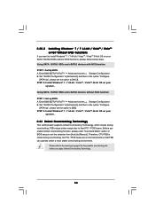
...Windows® 7 / 7 64-bit / VistaTM / VistaTM 64-bit Without RAID Functions If you apply Untied Overclocking Technology. 37 ASRock X58 Extreme3 Motherboard English Enter BIOS SETUP UTILITY Advanced screen Storage Configuration. B. Set "SATAII Configuration" to [Enhanced], and then in the option ...Technology, which means during overclocking, but PCI / PCIE buses are in the option "Configure SATAII as ", please set the selection from [Auto] to [Manual]. STEP 2: Install Windows® 7 / 7 64-bit / VistaTM / VistaTM 64-bit OS on page 8 for the possible overclocking risk before you...
...Windows® 7 / 7 64-bit / VistaTM / VistaTM 64-bit Without RAID Functions If you apply Untied Overclocking Technology. 37 ASRock X58 Extreme3 Motherboard English Enter BIOS SETUP UTILITY Advanced screen Storage Configuration. B. Set "SATAII Configuration" to [Enhanced], and then in the option ...Technology, which means during overclocking, but PCI / PCIE buses are in the option "Configure SATAII as ", please set the selection from [Auto] to [Manual]. STEP 2: Install Windows® 7 / 7 64-bit / VistaTM / VistaTM 64-bit OS on page 8 for the possible overclocking risk before you...
