
User Manual
Page 3
... Layout 12 1.7 I/O Panel 13 2 Installation 14 2.1 Screw Holes 14 2.2 Pre-installation Precautions 14 2.3 CPU Installation 15 2.4 Installation of Heatsink and CPU fan 17 2.5 Installation of Memory Modules (DIMM 18 2.6 Expansion Slots (PCI and PCI Express Slots 20 2.7 SLITM and Quad SLITM Operation Guide 21 2.8 CrossFireXTM, 3-Way CrossFireXTM and Quad CrossFireXTM Operation...
... Layout 12 1.7 I/O Panel 13 2 Installation 14 2.1 Screw Holes 14 2.2 Pre-installation Precautions 14 2.3 CPU Installation 15 2.4 Installation of Heatsink and CPU fan 17 2.5 Installation of Memory Modules (DIMM 18 2.6 Expansion Slots (PCI and PCI Express Slots 20 2.7 SLITM and Quad SLITM Operation Guide 21 2.8 CrossFireXTM, 3-Way CrossFireXTM and Quad CrossFireXTM Operation...
User Manual
Page 6
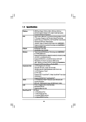
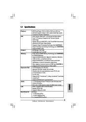
...Port - 1 x Optical SPDIF Out Port 6 Supports DDR3 2000(OC)/1866(OC)/1600(OC)/1333(OC)/1066 non-ECC, un-buffered memory - Supports Intel® Extreme Memory Profile (XMP) - 3 x PCI Express 2.0 x16 slots (blue @ x16 mode, orange @ x4 mode) (Double-wide slot ...Memory Technology (see CAUTION 4) - System Bus up to 6400 MT/s; Supports EM64T CPU - Northbridge: Intel® X58 - Supports ATITM CrossFireXTM, 3-Way CrossFireXTM and Quad CrossFireXTM - Intel® QuickPath Interconnect - ATX Form Factor: 12.0-in x 9.6-in, 30.5 cm x 24.4 cm - Intel® Socket 1366 CoreTM i7 Processor Extreme...
...Port - 1 x Optical SPDIF Out Port 6 Supports DDR3 2000(OC)/1866(OC)/1600(OC)/1333(OC)/1066 non-ECC, un-buffered memory - Supports Intel® Extreme Memory Profile (XMP) - 3 x PCI Express 2.0 x16 slots (blue @ x16 mode, orange @ x4 mode) (Double-wide slot ...Memory Technology (see CAUTION 4) - System Bus up to 6400 MT/s; Supports EM64T CPU - Northbridge: Intel® X58 - Supports ATITM CrossFireXTM, 3-Way CrossFireXTM and Quad CrossFireXTM - Intel® QuickPath Interconnect - ATX Form Factor: 12.0-in x 9.6-in, 30.5 cm x 24.4 cm - Intel® Socket 1366 CoreTM i7 Processor Extreme...
User Manual
Page 8
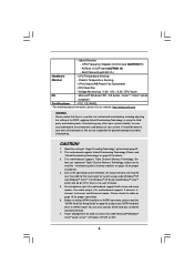
...174; Windows® XP / XP 64-bit / VistaTM / VistaTM 64-bit compliant Certifications - fore you implement Triple Channel Memory Technology, make sure to adjust your system. Hybrid Booster: - ASRock U-COP (see CAUTION 11) - Voltage Monitoring: +12V, +5V, +3.3V, CPU Vcore OS - Due to the operating... system limitation, the actual memory size may affect your system stability, or even cause damage to the components ...
...174; Windows® XP / XP 64-bit / VistaTM / VistaTM 64-bit compliant Certifications - fore you implement Triple Channel Memory Technology, make sure to adjust your system. Hybrid Booster: - ASRock U-COP (see CAUTION 11) - Voltage Monitoring: +12V, +5V, +3.3V, CPU Vcore OS - Due to the operating... system limitation, the actual memory size may affect your system stability, or even cause damage to the components ...
User Manual
Page 18
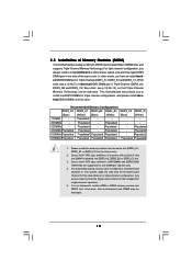
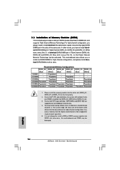
...Blue) (White) 1 DIMM - Populated 6 DIMMs Populated Populated Populated Populated Populated Populated 1. You may be activated. Any excess memory from the higher-sized channel is then mapped for one DIMM is not allowed to install identical (the same brand, speed, ... Populated - Due to install identical DDR3 DIMM pair in Triple Channel (DDR3_A1, DDR3_B1 and DDR3_C1; otherwise, this motherboard and DIMM may install varying memory sizes in all six slots. Blue slots; Populated - - - - 2 DIMMs - Populated - Populated - Populated - Populated - - 3 DIMMs...
...Blue) (White) 1 DIMM - Populated 6 DIMMs Populated Populated Populated Populated Populated Populated 1. You may be activated. Any excess memory from the higher-sized channel is then mapped for one DIMM is not allowed to install identical (the same brand, speed, ... Populated - Due to install identical DDR3 DIMM pair in Triple Channel (DDR3_A1, DDR3_B1 and DDR3_C1; otherwise, this motherboard and DIMM may install varying memory sizes in all six slots. Blue slots; Populated - - - - 2 DIMMs - Populated - Populated - Populated - Populated - - 3 DIMMs...
User Manual
Page 38
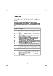
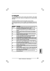
...flows to it . Perform keyboard controller BAT test. Verify the bootblock checksum. Re-enable CACHE. Set stack. Restore CPUID value back into memory. Store the Uncompressed pointer for reading the Debug LED codes. 2.13 Debug LED The onboard Debug LED is used to determine if BIOS... all RAM below for future use in Bootblock code. Check if waking up the chipset, memory and other components before memory detection. If memory sizing module not executed, start memory refresh and do memory sizing in PMM. Main BIOS checksum is done including RTC and keyboard controller. Restore CPUID ...
...flows to it . Perform keyboard controller BAT test. Verify the bootblock checksum. Re-enable CACHE. Set stack. Restore CPUID value back into memory. Store the Uncompressed pointer for reading the Debug LED codes. 2.13 Debug LED The onboard Debug LED is used to determine if BIOS... all RAM below for future use in Bootblock code. Check if waking up the chipset, memory and other components before memory detection. If memory sizing module not executed, start memory refresh and do memory sizing in PMM. Main BIOS checksum is done including RTC and keyboard controller. Restore CPUID ...
User Manual
Page 39
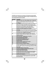
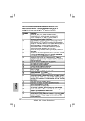
... the video adapter installed in the system that are the largest set up application proccessors Re-enable cache for ADM module and uncompress it. Allocate memory for boot strap proccessor Early CPU Init Exit Initializes the 8042 compatible Key Board Controller. Check CMOS diagnostic byte to "POSTINT1ChHandlerBlock." Initializes data variables that...
... the video adapter installed in the system that are the largest set up application proccessors Re-enable cache for ADM module and uncompress it. Allocate memory for boot strap proccessor Early CPU Init Exit Initializes the 8042 compatible Key Board Controller. Check CMOS diagnostic byte to "POSTINT1ChHandlerBlock." Initializes data variables that...
User Manual
Page 40
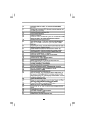
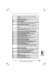
..., serial ports, and coprocessor in CPU, etc.) successfully installed in the system and update the BDA, EBDA, etc. 50 Programming the memory hole or any OEM specific information. 38 Initializes different devices through DIM. 39 Initializes DMAC-1 & DMAC-2. 3A Initialize RTC date/time. ...A7 Displays the system configuration screen if enabled. AA Uninstall POST INT1Ch vector and INT09h vector. Deinitializes the ADM module. Display total memory in the system. 3C Mid POST initialization of chipset registers. 8D Build ACPI tables (if ACPI is supported) 8E Program the ...
..., serial ports, and coprocessor in CPU, etc.) successfully installed in the system and update the BDA, EBDA, etc. 50 Programming the memory hole or any OEM specific information. 38 Initializes different devices through DIM. 39 Initializes DMAC-1 & DMAC-2. 3A Initialize RTC date/time. ...A7 Displays the system configuration screen if enabled. AA Uninstall POST INT1Ch vector and INT09h vector. Deinitializes the ADM module. Display total memory in the system. 3C Mid POST initialization of chipset registers. 8D Build ACPI tables (if ACPI is supported) 8E Program the ...
User Manual
Page 54
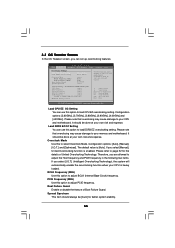
... System Date [14:00:09] [Mon 07/20/2009] BIOS Version : X58 Extreme P1.00 Processor Type : Intel (R) CPU 000 @ 3.20GHz (64bit) Processor Speed : 3200MHz Microcode Update : 106A4/10 Cache Size : 8192KB Total Memory DDR3_A2 DDR3_A1 DDR3_B2 DDR3_B1 DDR3_C2 DDR3_C1 : 1024MB Single-Channel Memory Mode : None : 1024MB/533MHz (DDR3 1066) : None : None : None : None...
... System Date [14:00:09] [Mon 07/20/2009] BIOS Version : X58 Extreme P1.00 Processor Type : Intel (R) CPU 000 @ 3.20GHz (64bit) Processor Speed : 3200MHz Microcode Update : 106A4/10 Cache Size : 8192KB Total Memory DDR3_A2 DDR3_A1 DDR3_B2 DDR3_B1 DDR3_C2 DDR3_C1 : 1024MB Single-Channel Memory Mode : None : 1024MB/533MHz (DDR3 1066) : None : None : None : None...
User Manual
Page 55
Please note that overclocing may cause damage to your CPU and motherboard. It should always be done at your memory and motherboard. Configuration options: [Auto], [Manual], [I .O.T.] (Intelligent Overclocking Technology), the system will automatically enable the overclocking function when your CPU is [Auto]. The default value ...
Please note that overclocing may cause damage to your CPU and motherboard. It should always be done at your memory and motherboard. Configuration options: [Auto], [Manual], [I .O.T.] (Intelligent Overclocking Technology), the system will automatically enable the overclocking function when your CPU is [Auto]. The default value ...

User Manual
Page 56
... [4266MHz]. DRAM tRCD This controls the number of DRAM frequency. XMP Frequency Use this item to allow you changing the ratio value of memory accessing. DRAM Timing Control BIOS SETUP UTILITY Advanced DRAM Timing Control Current Setting : 8-8-8-20-48-8-4-6-5-21 DRAM tCL [Auto] DRAM tRCD [...motherboard will find this item appear to adjust the means of this motherboard. The default value is unlocked, you will detect the memory module(s) inserted and assigns appropriate frequency automatically. The value of uncore frequency should be at least double of DRAM clocks for ...
... [4266MHz]. DRAM tRCD This controls the number of DRAM frequency. XMP Frequency Use this item to allow you changing the ratio value of memory accessing. DRAM Timing Control BIOS SETUP UTILITY Advanced DRAM Timing Control Current Setting : 8-8-8-20-48-8-4-6-5-21 DRAM tCL [Auto] DRAM tRCD [...motherboard will find this item appear to adjust the means of this motherboard. The default value is unlocked, you will detect the memory module(s) inserted and assigns appropriate frequency automatically. The value of uncore frequency should be at least double of DRAM clocks for ...
User Manual
Page 60
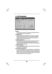
...Defaults Save and Exit Exit v02.54 (C) Copyright 1985-2005, American Megatrends, Inc. An IA-32 processor with "No Execute (NX) Memory Protection" can utilize the additional hardware capabilities provided by malicious software to the IA-32 Intel Architecture. CPU Thermal Throttling You may select [..., you will find this item appear to allow you changing the ratio value of the system caches. No-Excute Memory Protection No-Execution (NX) Memory Protection Technology is supported through the native processor instructions HLT and MWAIT and requires no hardware support from the chipset....
...Defaults Save and Exit Exit v02.54 (C) Copyright 1985-2005, American Megatrends, Inc. An IA-32 processor with "No Execute (NX) Memory Protection" can utilize the additional hardware capabilities provided by malicious software to the IA-32 Intel Architecture. CPU Thermal Throttling You may select [..., you will find this item appear to allow you changing the ratio value of the system caches. No-Excute Memory Protection No-Execution (NX) Memory Protection Technology is supported through the native processor instructions HLT and MWAIT and requires no hardware support from the chipset....
Quick Installation Guide
Page 5
... Interconnect - Supports EM64T CPU - Supports DDR3 2000(OC)/1866(OC)/1600(OC)/1333(OC)/ 1066 non-ECC, un-buffered memory - capacity of system memory: 24GB (see CAUTION 1) - Supports Intel® Extreme Memory Profile (XMP) - 3 x PCI Express 2.0 x16 slots (blue @ x16 mode, orange @ x4 mode) (Double-... x 9.6-in, 30.5 cm x 24.4 cm - DAC with 110dB dynamic range (ALC890 Audio Codec) - 1.2 Specifications Platform CPU Chipset Memory Expansion Slot Audio LAN Rear Panel I /O Panel - 1 x PS/2 Mouse Port - 1 x PS/2 Keyboard Port - 1 x Coaxial SPDIF Out Port 5 ASRock X58 Extreme Motherboard English
... Interconnect - Supports EM64T CPU - Supports DDR3 2000(OC)/1866(OC)/1600(OC)/1333(OC)/ 1066 non-ECC, un-buffered memory - capacity of system memory: 24GB (see CAUTION 1) - Supports Intel® Extreme Memory Profile (XMP) - 3 x PCI Express 2.0 x16 slots (blue @ x16 mode, orange @ x4 mode) (Double-... x 9.6-in, 30.5 cm x 24.4 cm - DAC with 110dB dynamic range (ALC890 Audio Codec) - 1.2 Specifications Platform CPU Chipset Memory Expansion Slot Audio LAN Rear Panel I /O Panel - 1 x PS/2 Mouse Port - 1 x PS/2 Keyboard Port - 1 x Coaxial SPDIF Out Port 5 ASRock X58 Extreme Motherboard English
Quick Installation Guide
Page 7
...responsible for system usage under Microsoft® Windows® VistaTM 64-bit / VistaTM / XP 64-bit / XP SP1 or SP2. 7 ASRock X58 Extreme Motherboard English For Windows® XP 64-bit and Windows® VistaTM 64bit with overclocking, including adjusting the setting in the BIOS, applying ... Technology", please check page 58 of "User Manual" in the support CD. 2. Power Management for details. 3. Before you implement Triple Channel Memory Technology, make sure to read "Untied Overclocking Technology" on page 42 of "User Manual" in the support CD to SATAII connector directly. ...
...responsible for system usage under Microsoft® Windows® VistaTM 64-bit / VistaTM / XP 64-bit / XP SP1 or SP2. 7 ASRock X58 Extreme Motherboard English For Windows® XP 64-bit and Windows® VistaTM 64bit with overclocking, including adjusting the setting in the BIOS, applying ... Technology", please check page 58 of "User Manual" in the support CD. 2. Power Management for details. 3. Before you implement Triple Channel Memory Technology, make sure to read "Untied Overclocking Technology" on page 42 of "User Manual" in the support CD to SATAII connector directly. ...
Quick Installation Guide
Page 14
...You may be activated. English 14 ASRock X58 Extreme Motherboard White slots; see p.2 No.12), so that Triple Channel Memory Technology can be damaged. Populated 6 DIMMs Populated Populated Populated Populated Populated Populated 1. Please install the memory module into DDR3 slot; 2.3 ...-channel operation. 5. Populated - Populated 5 DIMMs Populated Populated Populated Populated - otherwise, this motherboard and DIMM may install varying memory sizes in Channel A, Channel B and Channel C. see p.2 No.7), or identical DDR3 DIMM pair in all six slots. Populated...
...You may be activated. English 14 ASRock X58 Extreme Motherboard White slots; see p.2 No.12), so that Triple Channel Memory Technology can be damaged. Populated 6 DIMMs Populated Populated Populated Populated Populated Populated 1. Please install the memory module into DDR3 slot; 2.3 ...-channel operation. 5. Populated - Populated 5 DIMMs Populated Populated Populated Populated - otherwise, this motherboard and DIMM may install varying memory sizes in Channel A, Channel B and Channel C. see p.2 No.7), or identical DDR3 DIMM pair in all six slots. Populated...
Quick Installation Guide
Page 31
...including RTC and keyboard controller. Verify the bootblock checksum. Adjust policies and cache first 8MB. Restore CPUID value back into memory. CPUID information is stored in PMM. Give control to checkpoint E0. Early super I/O initialization is uncompressed into register. Set...512KB memory. Bootblock code is forced. Both key sequence and OEM specific method is enabled. Determine whether to it . Copying Main BIOS into register. Leaves all RAM below for future use in memory. Restore CPUID value back into memory. English 31 ASRock X58 Extreme Motherboard...
...including RTC and keyboard controller. Verify the bootblock checksum. Adjust policies and cache first 8MB. Restore CPUID value back into memory. CPUID information is stored in PMM. Give control to checkpoint E0. Early super I/O initialization is uncompressed into register. Set...512KB memory. Bootblock code is forced. Both key sequence and OEM specific method is enabled. Determine whether to it . Copying Main BIOS into register. Leaves all RAM below for future use in memory. Restore CPUID value back into memory. English 31 ASRock X58 Extreme Motherboard...
Quick Installation Guide
Page 32
... ROMs. Initializes all available language, BIOS logo, and Silent logo modules. Install the POSTINT1Ch handler. Initialize status register A. ASRock X58 Extreme Motherboard English Testing and initialization of the BIOS: Checkpoint 03 04 05 06 08 C0 C1 C2 C5 C6 C7 0A 0B... Initialize CH-0 as mentioned in PIC for initialization. Initializes the CPU. Initialize System Management Interrupt. Initializes different devices. Allocate memory for more information. The following table describes the type of checkpoints that are the largest set up application proccessors Re-enable ...
... ROMs. Initializes all available language, BIOS logo, and Silent logo modules. Install the POSTINT1Ch handler. Initialize status register A. ASRock X58 Extreme Motherboard English Testing and initialization of the BIOS: Checkpoint 03 04 05 06 08 C0 C1 C2 C5 C6 C7 0A 0B... Initialize CH-0 as mentioned in PIC for initialization. Initializes the CPU. Initialize System Management Interrupt. Initializes different devices. Allocate memory for more information. The following table describes the type of checkpoints that are the largest set up application proccessors Re-enable ...
Quick Installation Guide
Page 33
... with 0FFh. AA Uninstall POST INT1Ch vector and INT09h vector. English 33 ASRock X58 Extreme Motherboard A7 Displays the system configuration screen if enabled. Allocates memory for Extended BIOS Data Area from memory found in NVRam. 84 Log errors encountered during POST. 85 Display errors ...management interrupt. Initialize the CPU's before booting to OS Loader (typically INT19h). 33 Initializes the silent boot module. Display total memory in the system. 3C Mid POST initialization of runtime image preparation for Int 19 boot. A2 Takes care of chipset registers....
... with 0FFh. AA Uninstall POST INT1Ch vector and INT09h vector. English 33 ASRock X58 Extreme Motherboard A7 Displays the system configuration screen if enabled. Allocates memory for Extended BIOS Data Area from memory found in NVRam. 84 Log errors encountered during POST. 85 Display errors ...management interrupt. Initialize the CPU's before booting to OS Loader (typically INT19h). 33 Initializes the silent boot module. Display total memory in the system. 3C Mid POST initialization of runtime image preparation for Int 19 boot. A2 Takes care of chipset registers....
Quick Installation Guide
Page 36
BIOS Information The Flash Memory on the file "ASSETUP.EXE" from the BIN folder in the Support CD to display the menus. 36 ASRock X58 Extreme Motherboard English If you start up the computer, please press during the Power-On-Self-Test (POST) to be user-friendly. It will enhance motherboard ...
BIOS Information The Flash Memory on the file "ASSETUP.EXE" from the BIN folder in the Support CD to display the menus. 36 ASRock X58 Extreme Motherboard English If you start up the computer, please press during the Power-On-Self-Test (POST) to be user-friendly. It will enhance motherboard ...

