
User Manual
Page 4
... 64-bit Without RAID Functions 51 2.21.2 Installing Windows® VistaTM / VistaTM 64-bit Without RAID Functions 52 2.22 Untied Overclocking Technology 52 3 BIOS SETUP UTILITY 53 3.1 Introduction 53 3.1.1 BIOS Menu Bar 53 3.1.2 Navigation Keys 54 3.2 Main Screen 54 3.3 OC Tweaker Screen 54 3.4 Advanced Screen 59 3.4.1 CPU Configuration 60 3.4.2 Chipset Configuration 63...
... 64-bit Without RAID Functions 51 2.21.2 Installing Windows® VistaTM / VistaTM 64-bit Without RAID Functions 52 2.22 Untied Overclocking Technology 52 3 BIOS SETUP UTILITY 53 3.1 Introduction 53 3.1.1 BIOS Menu Bar 53 3.1.2 Navigation Keys 54 3.2 Main Screen 54 3.3 OC Tweaker Screen 54 3.4 Advanced Screen 59 3.4.1 CPU Configuration 60 3.4.2 Chipset Configuration 63...
User Manual
Page 5
... robust design conforming to ASRock's commitment to BIOS setup and information of this motherboard, please visit our website for specific information about the model you are using. www.asrock.com/support/index.asp 1.1 Package Contents ASRock X58 Extreme Motherboard (ATX Form Factor: 12.0-in x 9.6-in, 30.5 cm x 24.4 cm) ASRock X58 Extreme Quick Installation Guide ASRock X58 Extreme Support CD 1 x 80-conductor...
... robust design conforming to ASRock's commitment to BIOS setup and information of this motherboard, please visit our website for specific information about the model you are using. www.asrock.com/support/index.asp 1.1 Package Contents ASRock X58 Extreme Motherboard (ATX Form Factor: 12.0-in x 9.6-in, 30.5 cm x 24.4 cm) ASRock X58 Extreme Quick Installation Guide ASRock X58 Extreme Support CD 1 x 80-conductor...

User Manual
Page 7
... Tuner (see CAUTION 10) 7 ASRock Instant Flash (see CAUTION 8) - Connector Quick Switch BIOS Feature Support CD Unique Feature - 7 x Ready-to-...power connector - 8 pin 12V power connector - Supports Smart BIOS - Instant Boot - CPU, DRAM, NB, SB, VTT Voltage Multi-adjustment - Drivers, Utilities, AntiVirus Software ...(Trial Version) - AMI Legal BIOS - SMBIOS 2.3.1 Support - T. (Intelligent Overclocking Technology) - Front panel audio connector - 2 x USB 2.0 headers (support 4 USB 2.0 ports...
... Tuner (see CAUTION 10) 7 ASRock Instant Flash (see CAUTION 8) - Connector Quick Switch BIOS Feature Support CD Unique Feature - 7 x Ready-to-...power connector - 8 pin 12V power connector - Supports Smart BIOS - Instant Boot - CPU, DRAM, NB, SB, VTT Voltage Multi-adjustment - Drivers, Utilities, AntiVirus Software ...(Trial Version) - AMI Legal BIOS - SMBIOS 2.3.1 Support - T. (Intelligent Overclocking Technology) - Front panel audio connector - 2 x USB 2.0 headers (support 4 USB 2.0 ports...
User Manual
Page 8
...-bit / VistaTM / VistaTM 64-bit compliant Certifications - FCC, CE, WHQL * For detailed product information, please visit our website: http://www.asrock.com WARNING Please realize that there is no such limitation. 5. It should be less than 4GB for the reservation for proper connection. 6. This ...174; VistaTM 64-bit with 64-bit CPU, there is a certain risk involved with overclocking, including adjusting the setting in the BIOS, applying Untied Overclocking Technology, or using the thirdparty overclocking tools. You can also connect SATA hard disk to SATAII connector, please...
...-bit / VistaTM / VistaTM 64-bit compliant Certifications - FCC, CE, WHQL * For detailed product information, please visit our website: http://www.asrock.com WARNING Please realize that there is no such limitation. 5. It should be less than 4GB for the reservation for proper connection. 6. This ...174; VistaTM 64-bit with 64-bit CPU, there is a certain risk involved with overclocking, including adjusting the setting in the BIOS, applying Untied Overclocking Technology, or using the thirdparty overclocking tools. You can also connect SATA hard disk to SATAII connector, please...
User Manual
Page 9
... preparing an additional floppy diskette or other than the recommended CPU bus frequencies may cause the instability of ASRock OC Tuner. Just launch this motherboard offers stepless control, it back again. 8. This convenient BIOS update tool allows you to spray thermal grease between the CPU and the heatsink when you can press...
... preparing an additional floppy diskette or other than the recommended CPU bus frequencies may cause the instability of ASRock OC Tuner. Just launch this motherboard offers stepless control, it back again. 8. This convenient BIOS update tool allows you to spray thermal grease between the CPU and the heatsink when you can press...
User Manual
Page 12
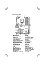
... PCIE1 13 PHY 38 PCI Express 2.0 CrossFireX QPI 6.4GT/s 37 36 AUDIO CODEC PCIE2 PCIE3 RoHS 14 1394a VIA VT6330 SATAII_5_6 SATAII_3_4 SATAII_1_2 35 PCI1 X58 Extreme 8Mb BIOS 34 PCIE4 IDE1 15 33 32 31 Super I/O 1 IR1 FLOPPY1 HDMI_SPDIF1 1 PCI2 PCIE5 COM1 1 1 TPM1 CMOS Battery Intel ICH10R USB10_11 CHA_FAN1 Debug CLRCMOS1 PWRBTN...
... PCIE1 13 PHY 38 PCI Express 2.0 CrossFireX QPI 6.4GT/s 37 36 AUDIO CODEC PCIE2 PCIE3 RoHS 14 1394a VIA VT6330 SATAII_5_6 SATAII_3_4 SATAII_1_2 35 PCI1 X58 Extreme 8Mb BIOS 34 PCIE4 IDE1 15 33 32 31 Super I/O 1 IR1 FLOPPY1 HDMI_SPDIF1 1 PCI2 PCIE5 COM1 1 1 TPM1 CMOS Battery Intel ICH10R USB10_11 CHA_FAN1 Debug CLRCMOS1 PWRBTN...
User Manual
Page 30
... do the clearCMOS action. 30 Jumper Setting Description PS2_USB_PWR1 1_2 (see p.12, No. 24) 1_2 2_3 Default Clear CMOS Note: CLRCMOS1 allows you update the BIOS. Clear CMOS Jumper (CLRCMOS1) (see p.12, No. 1) 2_3 Short pin2, pin3 to clear the CMOS when you just finish updating the... BIOS, you must boot up events. If you need to enable +5VSB (standby) for 5 seconds. For the detailed instruction, please refer to default setup, please turn ...
... do the clearCMOS action. 30 Jumper Setting Description PS2_USB_PWR1 1_2 (see p.12, No. 24) 1_2 2_3 Default Clear CMOS Note: CLRCMOS1 allows you update the BIOS. Clear CMOS Jumper (CLRCMOS1) (see p.12, No. 1) 2_3 Short pin2, pin3 to clear the CMOS when you just finish updating the... BIOS, you must boot up events. If you need to enable +5VSB (standby) for 5 seconds. For the detailed instruction, please refer to default setup, please turn ...
User Manual
Page 33
... audio panel. Connect Mic_IN (MIC) to install your voice through front mic, please deselect "Mute" icon in our manual and chassis manual to MIC2_L. D. Enter BIOS Setup Utility. Please follow the instruction in "Front Mic" of audio devices. 1.
... audio panel. Connect Mic_IN (MIC) to install your voice through front mic, please deselect "Mute" icon in our manual and chassis manual to MIC2_L. D. Enter BIOS Setup Utility. Please follow the instruction in "Front Mic" of audio devices. 1.
User Manual
Page 38
... chipset initialization. Test base 512KB memory. Restore CPUID value back into memory. The Runtime module is uncompressed into register. Copying Main BIOS into register. The Bootblock initialization code sets up from ROM to lower system memory and control is necessary, control flows to execute... Early chipset initialization is done. Restore CPUID value back into memory. 2.13 Debug LED The onboard Debug LED is used to BIOS POST (ExecutePOSTKernel). 38 Verify that flat mode is enabled. If memory sizing module not executed, start memory refresh and do memory...
... chipset initialization. Test base 512KB memory. Restore CPUID value back into memory. The Runtime module is uncompressed into register. Copying Main BIOS into register. The Bootblock initialization code sets up from ROM to lower system memory and control is necessary, control flows to execute... Early chipset initialization is done. Restore CPUID value back into memory. 2.13 Debug LED The onboard Debug LED is used to BIOS POST (ExecutePOSTKernel). 38 Verify that flat mode is enabled. If memory sizing module not executed, start memory refresh and do memory...
User Manual
Page 39
...adapter installed in the system that the POST INT09h handler gets control for system timer interrupt. Uncompress and initialize any platform specific BIOS modules. See DIM Code Checkpoints section of KB/MS using AMI KB-5. Enable IRQ-0 in the system Initializes the interrupt ...controlling hardware (generally PIC) and interrupt vector table. Initialize System Management Interrupt. Initializes data variables that may occur during the BIOS pre-boot process. Activate ADM module. 39 The following table describes the type of checkpoints that are the largest set up ...
...adapter installed in the system that the POST INT09h handler gets control for system timer interrupt. Uncompress and initialize any platform specific BIOS modules. See DIM Code Checkpoints section of KB/MS using AMI KB-5. Enable IRQ-0 in the system Initializes the interrupt ...controlling hardware (generally PIC) and interrupt vector table. Initialize System Management Interrupt. Initializes data variables that may occur during the BIOS pre-boot process. Activate ADM module. 39 The following table describes the type of checkpoints that are the largest set up ...
User Manual
Page 40
... 00 Passes control to the user and gets the user response for different BIOS modules. Enable/Disable NMI as selected 90 Late POST initialization of runtime image preparation for error. 87 Execute BIOS setup if needed / requested. 8C Late POST initialization of chipset registers.... 39 Initializes DMAC-1 & DMAC-2. 3A Initialize RTC date/time. 3B Test for IPL detection. 78 Initializes IPL devices controlled by BIOS and option ROMs. 7A Initializes remaining option ROMs. 7C Generate and write contents of chipset registers. A4 Initialize runtime language module. ...
... 00 Passes control to the user and gets the user response for different BIOS modules. Enable/Disable NMI as selected 90 Late POST initialization of runtime image preparation for error. 87 Execute BIOS setup if needed / requested. 8C Late POST initialization of chipset registers.... 39 Initializes DMAC-1 & DMAC-2. 3A Initialize RTC date/time. 3B Test for IPL detection. 78 Initializes IPL devices controlled by BIOS and option ROMs. 7A Initializes remaining option ROMs. 7C Generate and write contents of chipset registers. A4 Initialize runtime language module. ...
User Manual
Page 47
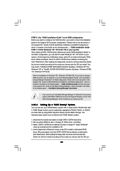
Enter BIOS SETUP UTILITY Advanced screen IDE Configuration. B. Insert the Support CD into the floppy drive. Please select CD-ROM as ", please set the option to [RAID]. ... Serial ATA driver diskette [YN]?", press . WARNING! Set "SATAII Configuration" to [Enhanced], and then in it! During POST at the beginning of system boot-up BIOS. C. E. A. Please insert a floppy diskette into the floppy diskette. 47 A. 2.19 Driver Installation Guide To install the drivers to your system, please insert the support CD...
Enter BIOS SETUP UTILITY Advanced screen IDE Configuration. B. Insert the Support CD into the floppy drive. Please select CD-ROM as ", please set the option to [RAID]. ... Serial ATA driver diskette [YN]?", press . WARNING! Set "SATAII Configuration" to [Enhanced], and then in it! During POST at the beginning of system boot-up BIOS. C. E. A. Please insert a floppy diskette into the floppy diskette. 47 A. 2.19 Driver Installation Guide To install the drivers to your system, please insert the support CD...
User Manual
Page 48
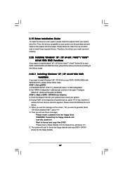
... diskette as well. 2.20.2 Setting Up a "RAID Ready" System You can be installed to your system. STEP 3: Use "RAID Installation Guide" to set up system BIOS as step 1 of Windows® setup, press F6 to install a third-party RAID driver. You may select: "Intel(R) ICH10R SATA RAID Controller (Desktop - After reading...
... diskette as well. 2.20.2 Setting Up a "RAID Ready" System You can be installed to your system. STEP 3: Use "RAID Installation Guide" to set up system BIOS as step 1 of Windows® setup, press F6 to install a third-party RAID driver. You may select: "Intel(R) ICH10R SATA RAID Controller (Desktop - After reading...

User Manual
Page 50
...the Intel® RAID drivers. B. Set "SATAII Configuration" to [Enhanced], and then in the option "Configure SATAII as well. 50 STEP 1: Set up BIOS. A. Please refer to the document in the Support CD, "Guide to SATA Hard Disks Installation and RAID Configuration", which is located in the folder at...VistaTM 64-bit OS) After that "Intel Matrix Storage Manager" will be installed to your system, and follow below steps. page, please insert the ASRock Support CD into your optical drive, and click the "Load Driver" button on the left on your system. Intel® RAID drivers are allowed to...
...the Intel® RAID drivers. B. Set "SATAII Configuration" to [Enhanced], and then in the option "Configure SATAII as well. 50 STEP 1: Set up BIOS. A. Please refer to the document in the Support CD, "Guide to SATA Hard Disks Installation and RAID Configuration", which is located in the folder at...VistaTM 64-bit OS) After that "Intel Matrix Storage Manager" will be installed to your system, and follow below steps. page, please insert the ASRock Support CD into your optical drive, and click the "Load Driver" button on the left on your system. Intel® RAID drivers are allowed to...
User Manual
Page 51
... your SATA / SATAII HDDs without RAID functions, please follow below steps. You may select: "Intel(R) ICH10R SATA AHCI Controller (Desktop - Enter BIOS SETUP UTILITY Advanced screen IDE Configuration. 2.21 Installing Windows® XP / XP 64-bit / VistaTM / VistaTM 64-bit Without RAID Functions If..., insert the SATA / SATAII driver diskette containing the Intel® AHCI driver. Using SATA / SATAII HDDs without NCQ function STEP 1: Set up BIOS. Set "SATAII Configuration" to [Enhanced], and then in the option "Configure SATAII as ", please set the option to [IDE]. At the beginning...
... your SATA / SATAII HDDs without RAID functions, please follow below steps. You may select: "Intel(R) ICH10R SATA AHCI Controller (Desktop - Enter BIOS SETUP UTILITY Advanced screen IDE Configuration. 2.21 Installing Windows® XP / XP 64-bit / VistaTM / VistaTM 64-bit Without RAID Functions If..., insert the SATA / SATAII driver diskette containing the Intel® AHCI driver. Using SATA / SATAII HDDs without NCQ function STEP 1: Set up BIOS. Set "SATAII Configuration" to [Enhanced], and then in the option "Configure SATAII as ", please set the option to [IDE]. At the beginning...

User Manual
Page 52
...Set "SATAII Configuration" to fixed PCI / PCIE buses. When you see "Where do you enable Untied Overclocking function, please enter "Overclock Mode" option of BIOS setup to set the option to install Windows?" Before you want to [Manual]. B. A. STEP 2: Install Windows® VistaTM / VistaTM 64-bit OS ...OS on your SATA / SATAII HDDs without NCQ function STEP 1: Set up BIOS. Please refer to the warning on page 8 for the possible overclocking risk before you want to [AHCI]. page, please insert the ASRock Support CD into the optical drive again to [IDE]. Intel® AHCI ...
...Set "SATAII Configuration" to fixed PCI / PCIE buses. When you see "Where do you enable Untied Overclocking function, please enter "Overclock Mode" option of BIOS setup to set the option to install Windows?" Before you want to [Manual]. B. A. STEP 2: Install Windows® VistaTM / VistaTM 64-bit OS ...OS on your SATA / SATAII HDDs without NCQ function STEP 1: Set up BIOS. Please refer to the warning on page 8 for the possible overclocking risk before you want to [AHCI]. page, please insert the ASRock Support CD into the optical drive again to [IDE]. Intel® AHCI ...
User Manual
Page 53
... selections: Main To set up the system time/date information OC Tweaker To set up overclocking features Advanced To set up the advanced BIOS features H/W Monitor To display current hardware status Boot To set up the default system device to locate and load the Operating System Security...set up the computer. You may also restart by pressing the reset button on your system. The BIOS FWH chip on . Because the BIOS software is constantly being updated, the following BIOS setup screens and descriptions are for reference purpose only, and they may not exactly match what you ...
... selections: Main To set up the system time/date information OC Tweaker To set up overclocking features Advanced To set up the advanced BIOS features H/W Monitor To display current hardware status Boot To set up the default system device to locate and load the Operating System Security...set up the computer. You may also restart by pressing the reset button on your system. The BIOS FWH chip on . Because the BIOS software is constantly being updated, the following BIOS setup screens and descriptions are for reference purpose only, and they may not exactly match what you ...
User Manual
Page 54
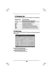
... Main OC Tweaker Advanced H/W Monitor Boot Security Exit System Overview System Time System Date [14:00:09] [Mon 07/20/2009] BIOS Version : X58 Extreme P1.00 Processor Type : Intel (R) CPU 000 @ 3.20GHz (64bit) Processor Speed : 3200MHz Microcode Update : 106A4/10 Cache Size : 8192KB Total Memory DDR3_A2 DDR3_A1 DDR3_B2 ... the function description of each navigation key. 3.1.2Navigation Keys Please check the following table for all the settings To save changes and exit the BIOS SETUP UTILITY To jump to the Exit Screen or exit the current screen 3.2 Main Screen When you enter the...
... Main OC Tweaker Advanced H/W Monitor Boot Security Exit System Overview System Time System Date [14:00:09] [Mon 07/20/2009] BIOS Version : X58 Extreme P1.00 Processor Type : Intel (R) CPU 000 @ 3.20GHz (64bit) Processor Speed : 3200MHz Microcode Update : 106A4/10 Cache Size : 8192KB Total Memory DDR3_A2 DDR3_A1 DDR3_B2 ... the function description of each navigation key. 3.1.2Navigation Keys Please check the following table for all the settings To save changes and exit the BIOS SETUP UTILITY To jump to the Exit Screen or exit the current screen 3.2 Main Screen When you enter the...
User Manual
Page 55
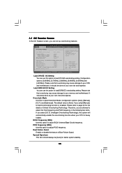
... options: [3.60GHz], [3.70GHz], [3.80GHz], [3.90GHz], [4.00GHz] and [4.20GHz]. 3.3 OC Tweaker Screen In the OC Tweaker screen, you can use this option to adjust PCIE frequency. BIOS SETUP UTILITY Main OC Tweaker Advanced H/W Monitor Boot Security Exit OC Tweaker Settings Load CPU EZ OC Setting Load DDR3 EZ OC Setting [Press Enter...
... options: [3.60GHz], [3.70GHz], [3.80GHz], [3.90GHz], [4.00GHz] and [4.20GHz]. 3.3 OC Tweaker Screen In the OC Tweaker screen, you can use this option to adjust PCIE frequency. BIOS SETUP UTILITY Main OC Tweaker Advanced H/W Monitor Boot Security Exit OC Tweaker Settings Load CPU EZ OC Setting Load DDR3 EZ OC Setting [Press Enter...

User Manual
Page 56
... selected, the motherboard will find this item appear to allow you will detect the memory module(s) inserted and assigns appropriate frequency automatically. DRAM Timing Control BIOS SETUP UTILITY Advanced DRAM Timing Control Current Setting : 8-8-8-20-48-8-4-6-5-21 DRAM tCL [Auto] DRAM tRCD [Auto] DRAM tRP [Auto] DRAM tRAS [Auto] DRAM tRFC...
... selected, the motherboard will find this item appear to allow you will detect the memory module(s) inserted and assigns appropriate frequency automatically. DRAM Timing Control BIOS SETUP UTILITY Advanced DRAM Timing Control Current Setting : 8-8-8-20-48-8-4-6-5-21 DRAM tCL [Auto] DRAM tRCD [Auto] DRAM tRP [Auto] DRAM tRAS [Auto] DRAM tRFC...


