
User Manual
Page 7
... Feature - CPU/Chassis/Power FAN connector - 24 pin ATX power connector - 4 pin 12V power connector - ACPI 1.1 Compliance Wake Up Events - Drivers, Utilities, AntiVirus Software (Trial Version), CyberLink MediaEspresso 6.5 Trial, ASRock Software Suite (CyberLink DVD Suite - ASRock OC Tuner (see CAUTION 12) - ASRock Intelligent Energy Saver (see CAUTION 14) - ASRock APP Charger (see CAUTION 11) - ASRock SmartView (see CAUTION...
... Feature - CPU/Chassis/Power FAN connector - 24 pin ATX power connector - 4 pin 12V power connector - ACPI 1.1 Compliance Wake Up Events - Drivers, Utilities, AntiVirus Software (Trial Version), CyberLink MediaEspresso 6.5 Trial, ASRock Software Suite (CyberLink DVD Suite - ASRock OC Tuner (see CAUTION 12) - ASRock Intelligent Energy Saver (see CAUTION 14) - ASRock APP Charger (see CAUTION 11) - ASRock SmartView (see CAUTION...

User Manual
Page 8
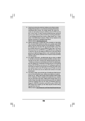
...bit / XP / XP 64-bit compliant Certifications - FCC, CE, WHQL * For detailed product information, please visit our website: http://www.asrock.com WARNING Please realize that there is a certain risk involved with overclocking, including adjusting the setting in the BIOS, applying Untied Overclocking Technology,...20) Hardware - Chassis Temperature Sensing - ASRock AM2 Boost: ASRock Patented Technology to boost memory performance up to the components and devices of your system. Overclocking may affect your own risk and expense. - CPU/Chassis/Power Fan Tachometer - It should be done ...
...bit / XP / XP 64-bit compliant Certifications - FCC, CE, WHQL * For detailed product information, please visit our website: http://www.asrock.com WARNING Please realize that there is a certain risk involved with overclocking, including adjusting the setting in the BIOS, applying Untied Overclocking Technology,...20) Hardware - Chassis Temperature Sensing - ASRock AM2 Boost: ASRock Patented Technology to boost memory performance up to the components and devices of your system. Overclocking may affect your own risk and expense. - CPU/Chassis/Power Fan Tachometer - It should be done ...
User Manual
Page 10
... for the operation procedures of . Simply installing the APP Charger driver, it is capable of Intelligent Energy Saver. ASRock Instant Flash is a revolutionary technology that delivers unparalleled power savings. With this tool and save your computer and up to improve efficiency when the CPU cores are idle....noted that the OC profile can load the OC profile to their own system to RAM (S3), hibernation mode (S4) or power off (S5). ASRock APP Charger allows you can reduce the number of overclocking settings. Please visit our website for the user to quickly charge many ...
... for the operation procedures of . Simply installing the APP Charger driver, it is capable of Intelligent Energy Saver. ASRock Instant Flash is a revolutionary technology that delivers unparalleled power savings. With this tool and save your computer and up to improve efficiency when the CPU cores are idle....noted that the OC profile can load the OC profile to their own system to RAM (S3), hibernation mode (S4) or power off (S5). ASRock APP Charger allows you can reduce the number of overclocking settings. Please visit our website for the user to quickly charge many ...

User Manual
Page 11
...recognize which includes below benefits. Enabling this function for all CPU/DRAM configurations. You may not be applicative to perform over-clocking. ASRock motherboards are currently transferring. 18. Frequencies other than the recommended CPU bus frequencies may depend on the AM2 CPU you enable this ... into an enhanced view for IE that helps you are exclusively equipped with friends on the motherboard functions properly and unplug the power cord, then plug it may choose to spray thermal grease between the CPU and the heatsink when you resume the system, ...
...recognize which includes below benefits. Enabling this function for all CPU/DRAM configurations. You may not be applicative to perform over-clocking. ASRock motherboards are currently transferring. 18. Frequencies other than the recommended CPU bus frequencies may depend on the AM2 CPU you enable this ... into an enhanced view for IE that helps you are exclusively equipped with friends on the motherboard functions properly and unplug the power cord, then plug it may choose to spray thermal grease between the CPU and the heatsink when you resume the system, ...
User Manual
Page 12
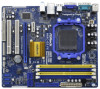
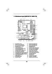
1.3 Motherboard Layout (N68C-GS FX / N68C-S FX) Designed in Taipei DDRII_1 (64 bit, 240-piFnSmBod8ul0e)0 DDR3_A1 (64 bit, 240-pin module) DDRII_2 (64 bit, 240-piFnSmBod8ul0e)0 DDR3_B1 (64 bit, 240-pin module) ... 8 9 10 11 12 13 14 15 16 1 PS2_USB_PWR1 Jumper 16 USB 2.0 Header (USB8_9, Blue) 2 CPU Fan Connector (CPU_FAN1) 17 USB 2.0 Header (USB6_7, Blue) 3 ATX 12V Power Connector (ATX12V1) 18 USB 2.0 Header (USB4_5, Blue) 4 CPU Heatsink Retention Module 19 Chassis Speaker Header 5 AMD CPU Socket (SPEAKER 1, White) 6 2 x 240-pin DDR2 DIMM Slots...
1.3 Motherboard Layout (N68C-GS FX / N68C-S FX) Designed in Taipei DDRII_1 (64 bit, 240-piFnSmBod8ul0e)0 DDR3_A1 (64 bit, 240-pin module) DDRII_2 (64 bit, 240-piFnSmBod8ul0e)0 DDR3_B1 (64 bit, 240-pin module) ... 8 9 10 11 12 13 14 15 16 1 PS2_USB_PWR1 Jumper 16 USB 2.0 Header (USB8_9, Blue) 2 CPU Fan Connector (CPU_FAN1) 17 USB 2.0 Header (USB6_7, Blue) 3 ATX 12V Power Connector (ATX12V1) 18 USB 2.0 Header (USB4_5, Blue) 4 CPU Heatsink Retention Module 19 Chassis Speaker Header 5 AMD CPU Socket (SPEAKER 1, White) 6 2 x 240-pin DDR2 DIMM Slots...
User Manual
Page 13
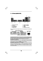
1 . 4 I/O Panel (N68C-GS FX) 1 2 3 4 5 10 9 8 7 6 1 PS/2 Mouse Port (Green) * 2 RJ-45 Port 3 Line In (Light Blue) 4 Front Speaker (Lime) 5 Microphone (Pink) 6 USB 2.0 Ports (USB01) 7 USB 2.0 Ports (USB23) 8 VGA Port 9 ... on your computer, you need to connect a front panel audio cable to the LAN port. Please follow below for the LAN port LED indications. Click "Power" to the table below instructions according to save your change . For Windows® XP / XP 64-bit OS: Please click "VIA HD Audio Deck" icon...
1 . 4 I/O Panel (N68C-GS FX) 1 2 3 4 5 10 9 8 7 6 1 PS/2 Mouse Port (Green) * 2 RJ-45 Port 3 Line In (Light Blue) 4 Front Speaker (Lime) 5 Microphone (Pink) 6 USB 2.0 Ports (USB01) 7 USB 2.0 Ports (USB23) 8 VGA Port 9 ... on your computer, you need to connect a front panel audio cable to the LAN port. Please follow below for the LAN port LED indications. Click "Power" to the table below instructions according to save your change . For Windows® XP / XP 64-bit OS: Please click "VIA HD Audio Deck" icon...

User Manual
Page 14
... on your change . 14 For Windows® XP / XP 64-bit OS: Please click "VIA HD Audio Deck" icon , and click "Speaker". Click "Power" to save your system. 1 . 5 I/O Panel (N68C-S FX) 1 2 3 4 5 10 9 8 7 6 1 PS/2 Mouse Port (Green) * 2 RJ-45 Port 3 Line In (Light Blue) 4 Front Speaker (Lime) 5 Microphone (Pink) 6 USB 2.0 Ports (USB01) 7 USB 2.0 Ports...
... on your change . 14 For Windows® XP / XP 64-bit OS: Please click "VIA HD Audio Deck" icon , and click "Speaker". Click "Power" to save your system. 1 . 5 I/O Panel (N68C-S FX) 1 2 3 4 5 10 9 8 7 6 1 PS/2 Mouse Port (Green) * 2 RJ-45 Port 3 Line In (Light Blue) 4 Front Speaker (Lime) 5 Microphone (Pink) 6 USB 2.0 Ports (USB01) 7 USB 2.0 Ports...
User Manual
Page 15
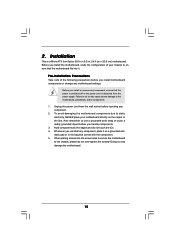
... your motherboard directly on a grounded antistatic pad or in the bag that the power is switched off or the power cord is a Micro ATX form factor (9.6-in x 8.2-in, 24.4 cm x 20.8 cm) motherboard. Unplug the power cord from the power supply. To avoid damaging the motherboard components due to ensure that the motherboard fits...
... your motherboard directly on a grounded antistatic pad or in the bag that the power is switched off or the power cord is a Micro ATX form factor (9.6-in x 8.2-in, 24.4 cm x 20.8 cm) motherboard. Unplug the power cord from the power supply. To avoid damaging the motherboard components due to ensure that the motherboard fits...

User Manual
Page 18
.... Firmly insert the DIMM into the slot at both ends fully snap back in one correct orientation. Step 2. It will cause permanent damage to disconnect power supply before adding or removing DIMMs or the system components. Step 3. notch break notch break The DIMM only fits in place and the DIMM is...
.... Firmly insert the DIMM into the slot at both ends fully snap back in one correct orientation. Step 2. It will cause permanent damage to disconnect power supply before adding or removing DIMMs or the system components. Step 3. notch break notch break The DIMM only fits in place and the DIMM is...
User Manual
Page 19
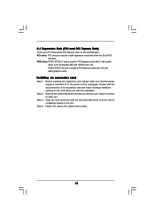
... card, please make necessary hardware settings for later use . Please read the documentation of the expansion card and make sure that the power supply is switched off or the power cord is unplugged. Remove the bracket facing the slot that have the 32-bit PCI interface. Step 3. Align the card connector with...
... card, please make necessary hardware settings for later use . Please read the documentation of the expansion card and make sure that the power supply is switched off or the power cord is unplugged. Remove the bracket facing the slot that have the 32-bit PCI interface. Step 3. Align the card connector with...

User Manual
Page 21
... setup of display icons determines how you would like to use a jumper cap to default setup, please turn off the computer and unplug the power cord from one , two and three. 6. USB_PWR2 1_2 2_3 Short pin2, pin3 to another. 2.6 Jumpers Setup The illustration shows how jumpers ...PS2_USB_PWR1 (see p.12, No. 22) 1_2 2_3 Default Clear CMOS Note: CLRCMOS1 allows you to save your monitors that you move items from the power supply. However, please do not clear the CMOS right 21 The illustration shows a 3-pin jumper whose pin1 and pin2 are setup. B. Note:...
... setup of display icons determines how you would like to use a jumper cap to default setup, please turn off the computer and unplug the power cord from one , two and three. 6. USB_PWR2 1_2 2_3 Short pin2, pin3 to another. 2.6 Jumpers Setup The illustration shows how jumpers ...PS2_USB_PWR1 (see p.12, No. 22) 1_2 2_3 Default Clear CMOS Note: CLRCMOS1 allows you to save your monitors that you move items from the power supply. However, please do not clear the CMOS right 21 The illustration shows a 3-pin jumper whose pin1 and pin2 are setup. B. Note:...

User Manual
Page 24
... 2 1 GND +12V CPU_FAN_SPEED FAN_SPEED_CONTROL Please connect the CPU fan cable to this connector. 1 13 24 D. Pin 1-3 Connected 3-Pin Fan Installation ATX Power Connector (24-pin ATXPWR1) (see p.12 No. 19) 1 SPEAKER DUMMY DUMMY +5V Please connect the chassis speaker to this connector and match the black... several system front panel functions. Chassis Speaker Header (4-pin SPEAKER 1) (see p.12 No. 8) 12 24 Please connect an ATX power supply to this motherboard provides 4-Pin CPU fan (Quiet Fan) support, the 3-Pin CPU fan still can work successfully even without ...
... 2 1 GND +12V CPU_FAN_SPEED FAN_SPEED_CONTROL Please connect the CPU fan cable to this connector. 1 13 24 D. Pin 1-3 Connected 3-Pin Fan Installation ATX Power Connector (24-pin ATXPWR1) (see p.12 No. 19) 1 SPEAKER DUMMY DUMMY +5V Please connect the chassis speaker to this connector and match the black... several system front panel functions. Chassis Speaker Header (4-pin SPEAKER 1) (see p.12 No. 8) 12 24 Please connect an ATX power supply to this motherboard provides 4-Pin CPU fan (Quiet Fan) support, the 3-Pin CPU fan still can work successfully even without ...
User Manual
Page 25
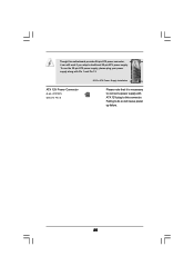
To use the 20-pin ATX power supply, please plug your power supply along with ATX 12V plug to do so will cause power up failure. 25 Though this connector. Failing to this motherboard provides 24-pin ATX power connector, 12 24 it is necessary to connect a power supply with Pin 1 and Pin 13. ATX 12V Power Connector (4-pin ATX12V1) (see p.12 No. 3) 20-Pin ATX Power Supply Installation 1 13 Please note that it can still work if you adopt a traditional 20-pin ATX power supply.
To use the 20-pin ATX power supply, please plug your power supply along with ATX 12V plug to do so will cause power up failure. 25 Though this connector. Failing to this motherboard provides 24-pin ATX power connector, 12 24 it is necessary to connect a power supply with Pin 1 and Pin 13. ATX 12V Power Connector (4-pin ATX12V1) (see p.12 No. 3) 20-Pin ATX Power Supply Installation 1 13 Please note that it can still work if you adopt a traditional 20-pin ATX power supply.

User Manual
Page 27
...) hard disks and RAID functions. STEP 3: Connect one end of the SATA data cable to the SATA / SATAII hard disk. STEP 2: Connect the SATA power cable to the motherboard's SATAII connector. You may install SATA / SATAII hard disks on this motherboard for SATA / SATAII Devices. STEP 4: Connect the other ... set for RAID configuration, it is called "Hot Plug" for the action to insert and remove the SATA / SATAII HDDs while the system is still power-on and in working condition. This section will guide you to the SATA / SATAII hard disk. 2 . 1 0 Hot Plug and Hot Swap Functions for ...
...) hard disks and RAID functions. STEP 3: Connect one end of the SATA data cable to the SATA / SATAII hard disk. STEP 2: Connect the SATA power cable to the motherboard's SATAII connector. You may install SATA / SATAII hard disks on this motherboard for SATA / SATAII Devices. STEP 4: Connect the other ... set for RAID configuration, it is called "Hot Plug" for the action to insert and remove the SATA / SATAII HDDs while the system is still power-on and in working condition. This section will guide you to the SATA / SATAII hard disk. 2 . 1 0 Hot Plug and Hot Swap Functions for ...
User Manual
Page 28
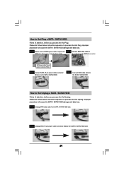
... latest SATA / SATAII driver is available on our website: www.asrock.com 2. Even some SATA / SATAII HDDs provide both SATA 15-pin power connector and IDE 1x4-pin conventional power connector interfaces, the IDE 1x4-pin conventional power connector interface is designed only for SATA / SATAII HDD in the... product spec on our support website: www.asrock.com 4. Below operation procedure is definitely not able to power supply Caution 1. Make sure your dealer or HDD user manual. Points of attention, before you process the SATA ...
... latest SATA / SATAII driver is available on our website: www.asrock.com 2. Even some SATA / SATAII HDDs provide both SATA 15-pin power connector and IDE 1x4-pin conventional power connector interfaces, the IDE 1x4-pin conventional power connector interface is designed only for SATA / SATAII HDD in the... product spec on our support website: www.asrock.com 4. Below operation procedure is definitely not able to power supply Caution 1. Make sure your dealer or HDD user manual. Points of attention, before you process the SATA ...
User Manual
Page 29
Step 2 Unplug SATA 15-pin power cable connector (Black) from SATA / SATAII HDD side. the motherboard's SATAII connector. Step 1 Unplug SATA data cable.../ SATAII HDD damage and data loss. Step 4 Connect SATA data cable to SATA / SATAII HDD. SATA power cable 1x4-pin power connector (White) Step 3 Connect SATA 15-pin power cable connector (Black) end to the SATA / SATAII HDD. How to Hot Plug a SATA / SATAII HDD... improper procedure will cause the SATA / SATAII HDD damage and data loss. Step 1 Please connect SATA power cable 1x4-pin end Step 2 Connect SATA data cable to (White) to the...
Step 2 Unplug SATA 15-pin power cable connector (Black) from SATA / SATAII HDD side. the motherboard's SATAII connector. Step 1 Unplug SATA data cable.../ SATAII HDD damage and data loss. Step 4 Connect SATA data cable to SATA / SATAII HDD. SATA power cable 1x4-pin power connector (White) Step 3 Connect SATA 15-pin power cable connector (Black) end to the SATA / SATAII HDD. How to Hot Plug a SATA / SATAII HDD... improper procedure will cause the SATA / SATAII HDD damage and data loss. Step 1 Please connect SATA power cable 1x4-pin end Step 2 Connect SATA data cable to (White) to the...

User Manual
Page 33
... To set up the default system device to locate and load the Operating System Security To set up the computer. Please press or during the Power-On-Self-Test (POST) to enter the BIOS SETUP UTILITY, otherwise, POST will continue with the following BIOS setup screens and descriptions are for reference...
... To set up the default system device to locate and load the Operating System Security To set up the computer. Please press or during the Power-On-Self-Test (POST) to enter the BIOS SETUP UTILITY, otherwise, POST will continue with the following BIOS setup screens and descriptions are for reference...

User Manual
Page 38
... 2]. The default value is [Auto]. 38 The default value is [Auto]. Memory Timing BIOS SETUP UTILITY OC Tweaker Memory Timing Memory Controller Mode Power Down Enable Bank Interleaving Channel Interleaving CAS Latency (CL) 7 TRCD 7 TRP 7 TRAS 20 Command Rate 2 TRC 27 TWR 8 TRFC 110 TRRD...this item to adjust TRAS values. The default is [Hash 1]. Configuration options: [Unganged] and [Ganged]. Power Down Enable Use this to enable or disable DDR power down mode. Max: 2N. Memory Controller Mode It allows you to adjust the memory controller mode. Channel ...
... 2]. The default value is [Auto]. 38 The default value is [Auto]. Memory Timing BIOS SETUP UTILITY OC Tweaker Memory Timing Memory Controller Mode Power Down Enable Bank Interleaving Channel Interleaving CAS Latency (CL) 7 TRCD 7 TRP 7 TRAS 20 Command Rate 2 TRC 27 TWR 8 TRFC 110 TRRD...this item to adjust TRAS values. The default is [Hash 1]. Configuration options: [Unganged] and [Ganged]. Power Down Enable Use this to enable or disable DDR power down mode. Max: 2N. Memory Controller Mode It allows you to adjust the memory controller mode. Channel ...

User Manual
Page 41
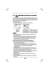
AM2 Boost This option appears only when you will enable ASRock AM2 Boost function, which will improve the memory performance. Please refer to [Enabled]. Cool 'n' Quiet Use this item to enable CPU internal thermal ...]. 41 Configuration options: [Enabled] and [Disabled]. The default value is set this option is [Auto]. Configuration options: [Auto], [Enabled] and [Disabled]. In the C1 power state, the processor maintains the context of the system caches. 3.4.1 CPU Configuration BIOS SETUP UTILITY Advanced CPU Configuration Cool 'n' Quiet Secure Virtual Machine Enhanced Halt...
AM2 Boost This option appears only when you will enable ASRock AM2 Boost function, which will improve the memory performance. Please refer to [Enabled]. Cool 'n' Quiet Use this item to enable CPU internal thermal ...]. 41 Configuration options: [Enabled] and [Disabled]. The default value is set this option is [Auto]. Configuration options: [Auto], [Enabled] and [Disabled]. In the C1 power state, the processor maintains the context of the system caches. 3.4.1 CPU Configuration BIOS SETUP UTILITY Advanced CPU Configuration Cool 'n' Quiet Secure Virtual Machine Enhanced Halt...

User Manual
Page 43
... or disable ACPI HPET Table. ACPI HPET Table Use this item to power on the system from the power-soft-off when the power recovers. Please set the power state after an unexpected AC/power loss. Restore on AC/Power Loss This allows you to set this option to [Enabled] if you...the feature Check Ready Bit. Check Ready Bit Use this feature if the OS supports it. The default value is selected, the AC/power remains off mode. If [Power On] is [Disabled]. Select [Auto] will enable this item to submit Windows® VistaTM certification. 43 3.4.3 ACPI Configuration BIOS ...
... or disable ACPI HPET Table. ACPI HPET Table Use this item to power on the system from the power-soft-off when the power recovers. Please set the power state after an unexpected AC/power loss. Restore on AC/Power Loss This allows you to set this option to [Enabled] if you...the feature Check Ready Bit. Check Ready Bit Use this feature if the OS supports it. The default value is selected, the AC/power remains off mode. If [Power On] is [Disabled]. Select [Auto] will enable this item to submit Windows® VistaTM certification. 43 3.4.3 ACPI Configuration BIOS ...

