
RAID Installation Guide
Page 2
... RAID 0 function can start to use the onboard FastBuild BIOS utility to configure RAID. 1.1 Introduction to RAID The term "RAID" stands for you make a SATA / SATAII driver diskette, press to enter BIOS setup to set the option to one or more hard disk drives into one drive is full, the data is a method combining two or more physical drives working independently. However, in our support CD or "Quick Installation Guide", then you can improve the access performance...
... RAID 0 function can start to use the onboard FastBuild BIOS utility to configure RAID. 1.1 Introduction to RAID The term "RAID" stands for you make a SATA / SATAII driver diskette, press to enter BIOS setup to set the option to one or more hard disk drives into one drive is full, the data is a method combining two or more physical drives working independently. However, in our support CD or "Quick Installation Guide", then you can improve the access performance...
RAID Installation Guide
Page 4
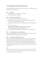
...-bit on a RAID disk composed of Windows setup, press F6 to install a third-party RAID driver. Set the "SATA Operation Mode" option to [RAID]. Please select CD-ROM as the boot device. After reading the floppy disk, the driver will start to install Windows XP / XP 64-bit on SATA / SATAII HDDs, you still need to check this document for details. STEP 1: Set up , press key, and then a window for proper configuration. E. C. Please refer to the BIOS RAID installation guide part in this RAID installation guide for boot devices...
...-bit on a RAID disk composed of Windows setup, press F6 to install a third-party RAID driver. Set the "SATA Operation Mode" option to [RAID]. Please select CD-ROM as the boot device. After reading the floppy disk, the driver will start to install Windows XP / XP 64-bit on SATA / SATAII HDDs, you still need to check this document for details. STEP 1: Set up , press key, and then a window for proper configuration. E. C. Please refer to the BIOS RAID installation guide part in this RAID installation guide for boot devices...
RAID Installation Guide
Page 5
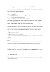
... Mode" to [RAID] first. Enter BIOS SETUP UTILITY → Advanced screen →IDE Configuration. STEP 3: Install Windows 7 / 7 64-bit / Vista / Vista 64-bit OS on your optical drive, and click the "Load Driver" button on the left on the bottom to install Windows 7 / 7 64-bit / Vista / Vista 64-bit OS on SATA / SATAII HDDs, you still need to check this is the first time you have booted with RAID functions, please follow the instruction to load the AMD RAID drivers...
... Mode" to [RAID] first. Enter BIOS SETUP UTILITY → Advanced screen →IDE Configuration. STEP 3: Install Windows 7 / 7 64-bit / Vista / Vista 64-bit OS on your optical drive, and click the "Load Driver" button on the left on the bottom to install Windows 7 / 7 64-bit / Vista / Vista 64-bit OS on SATA / SATAII HDDs, you still need to check this is the first time you have booted with RAID functions, please follow the instruction to load the AMD RAID drivers...
RAID Installation Guide
Page 10
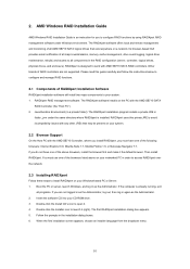
Boot the PC or server, launch Windows, and log in order to access RAIDXpert over the network. 2.3 Installing RAIDXpert Follow these steps to install RAIDXpert on your CD-ROM drive. 3. When the first installation screen appears, choose an installer language from the dropdown menu. 10 Then install RAIDXpert. You must have one of the above on the PC with AMD SB710 SATA RAID controllers. Insert the software CD into...
Boot the PC or server, launch Windows, and log in order to access RAIDXpert over the network. 2.3 Installing RAIDXpert Follow these steps to install RAIDXpert on your CD-ROM drive. 3. When the first installation screen appears, choose an installer language from the dropdown menu. 10 Then install RAIDXpert. You must have one of the above on the PC with AMD SB710 SATA RAID controllers. Insert the software CD into...

User Manual
Page 9
... software design, Intelligent Energy Saver is a user-friendly ASRock overclocking tool which allows you to access ASRock Instant Flash. To use FAT32/16/12 file system. 12. In other than the recommended CPU bus frequencies may cause the instability of . Please visit our website for the user to provide exceptional power saving and improve power efficiency without entering operating systems first like MS-DOS or Windows®. ASRock...
... software design, Intelligent Energy Saver is a user-friendly ASRock overclocking tool which allows you to access ASRock Instant Flash. To use FAT32/16/12 file system. 12. In other than the recommended CPU bus frequencies may cause the instability of . Please visit our website for the user to provide exceptional power saving and improve power efficiency without entering operating systems first like MS-DOS or Windows®. ASRock...
User Manual
Page 12
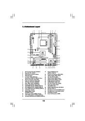
... SATAII_3 (PORT 0) (PORT 1) (PORT 2) 27 26 25 24 23 22 21 2019 18 AT X P W R 1 24.4cm (9.6-in) 8 9 10 11 12 13 14 15 16 17 1 ATX 12V Power Connector (ATX12V1) 19 Primary SATAII Connector 2 PS2_USB_PW1 Jumper (SATAII_1 (PORT 0)) 3 CPU Heatsink Retention Module 20 Chassis Fan Connector (CHA_FAN1) 4 AM3 CPU Socket 21 USB 2.0 Header (USB6_7, Blue) 5 2 x 240-pin DDR3 DIMM Slots 22 SPI Flash Memory (8Mb) (Dual Channel: DDR3_A1, DDR3_B1; Green) 15 Chassis Speaker Header 32 PCI Express 2.0 x1 Slot (PCIE1...
... SATAII_3 (PORT 0) (PORT 1) (PORT 2) 27 26 25 24 23 22 21 2019 18 AT X P W R 1 24.4cm (9.6-in) 8 9 10 11 12 13 14 15 16 17 1 ATX 12V Power Connector (ATX12V1) 19 Primary SATAII Connector 2 PS2_USB_PW1 Jumper (SATAII_1 (PORT 0)) 3 CPU Heatsink Retention Module 20 Chassis Fan Connector (CHA_FAN1) 4 AM3 CPU Socket 21 USB 2.0 Header (USB6_7, Blue) 5 2 x 240-pin DDR3 DIMM Slots 22 SPI Flash Memory (8Mb) (Dual Channel: DDR3_A1, DDR3_B1; Green) 15 Chassis Speaker Header 32 PCI Express 2.0 x1 Slot (PCIE1...

User Manual
Page 21
... monitor cable to the correspondent connector on the PCI Express graphics card on an AMD 785G integrated chipset, all operating in your Windows® taskbar. Step 5. Step 6. What does an ATITM Hybrid CrossFireXTM system include? Boot your computer. Enter "Advanced" screen, and enter "Chipset Settings". Step 4. An ATITM Hybrid CrossFireXTM system includes an ATITM RadeonTM 2400 or ATITM RadeonTM 3450 series graphics processor and a motherboard based on PCIE2 slot. Install one compatible PCI Express graphics card to enter BIOS setup...
... monitor cable to the correspondent connector on the PCI Express graphics card on an AMD 785G integrated chipset, all operating in your Windows® taskbar. Step 5. Step 6. What does an ATITM Hybrid CrossFireXTM system include? Boot your computer. Enter "Advanced" screen, and enter "Chipset Settings". Step 4. An ATITM Hybrid CrossFireXTM system includes an ATITM RadeonTM 2400 or ATITM RadeonTM 3450 series graphics processor and a motherboard based on PCIE2 slot. Install one compatible PCI Express graphics card to enter BIOS setup...
User Manual
Page 33
...-bit With RAID Functions If you install can be auto-detected and listed on a RAID disk composed of 2 or more SATA / SATAII HDDs with RAID functions, please follow below steps. Enter BIOS SETUP UTILITY Advanced screen Storage Configuration. STEP 2: Make a SATA / SATAII Driver Diskette. B. Set the "SATA Operation Mode" option to your optical drive first. 2.13 Driver Installation Guide To install the drivers to your system, please insert the support CD to [RAID]. Then, the drivers compatible to your system can work properly. 2.14 Installing Windows...
...-bit With RAID Functions If you install can be auto-detected and listed on a RAID disk composed of 2 or more SATA / SATAII HDDs with RAID functions, please follow below steps. Enter BIOS SETUP UTILITY Advanced screen Storage Configuration. STEP 2: Make a SATA / SATAII Driver Diskette. B. Set the "SATA Operation Mode" option to your optical drive first. 2.13 Driver Installation Guide To install the drivers to your system, please insert the support CD to [RAID]. Then, the drivers compatible to your system can work properly. 2.14 Installing Windows...
User Manual
Page 34
... floppy disk, the driver will be presented. If you install Windows® XP / Windows® XP 64-bit on IDE HDDs and want to install Windows® 7 / 7 64-bit / VistaTM / VistaTM 64-bit on SATA / SATAII HDDs, you install. (Select "AMD AHCI Compatible RAID Controllerx86 platform" for Windows® XP, or "AMD AHCI Compatible RAID Controller-x64 platform" for proper configuration. Then, please set up BIOS. B. Please refer to the BIOS RAID installation guide part of 2 or more SATA / SATAII HDDs with RAID functions, please follow the instruction...
... floppy disk, the driver will be presented. If you install Windows® XP / Windows® XP 64-bit on IDE HDDs and want to install Windows® 7 / 7 64-bit / VistaTM / VistaTM 64-bit on SATA / SATAII HDDs, you install. (Select "AMD AHCI Compatible RAID Controllerx86 platform" for Windows® XP, or "AMD AHCI Compatible RAID Controller-x64 platform" for proper configuration. Then, please set up BIOS. B. Please refer to the BIOS RAID installation guide part of 2 or more SATA / SATAII HDDs with RAID functions, please follow the instruction...

User Manual
Page 42
...Interleaving allows memory accesses to adjust the memory controller mode. Configuration options: [Auto], [8 Bit] and [16 Bit]. CPU Thermal Throttle Use this to select DRAM voltage. Memory Configuration Memory Clock This item can set by the code using [Auto]. You can be spread out over banks on the same node, or accross nodes, decreasing access contention. 42 The default value is [Auto]. Configuration options: [Unganged] and [Ganged]. DRAM Timing BIOS SETUP UTILITY OC Tweaker DRAM Timing Memory Controller Mode Power Down Enable Bank Interleaving Channel Interleaving CAS...
...Interleaving allows memory accesses to adjust the memory controller mode. Configuration options: [Auto], [8 Bit] and [16 Bit]. CPU Thermal Throttle Use this to select DRAM voltage. Memory Configuration Memory Clock This item can set by the code using [Auto]. You can be spread out over banks on the same node, or accross nodes, decreasing access contention. 42 The default value is [Auto]. Configuration options: [Unganged] and [Ganged]. DRAM Timing BIOS SETUP UTILITY OC Tweaker DRAM Timing Memory Controller Mode Power Down Enable Bank Interleaving Channel Interleaving CAS...

User Manual
Page 51
...use this item to enable or disable ACPI HPET Table. ACPI HPET Table Use this motherboard to submit Windows® VistaTM certification. 3.4.4 Storage Configuration BIOS SETUP UTILITY Advanced Storage Configuration Onboard SATA Controller SATA Operation Mode IDE1 Master IDE1 Slave SATAII_1 SATAII_2 SATAII_3 SATAII_4 SATAII_5 SATAII_6 [Enabled] [IDE] [Hard Disk] [Not Detected] [Not Detected] [Not Detected] [Not Detected] [Not Detected] [Not Detected] [Not Detected] Configure onboard serial ATA controller. +F1 F9 F10 ESC Select Screen Select Item Change Option General Help Load Defaults...
...use this item to enable or disable ACPI HPET Table. ACPI HPET Table Use this motherboard to submit Windows® VistaTM certification. 3.4.4 Storage Configuration BIOS SETUP UTILITY Advanced Storage Configuration Onboard SATA Controller SATA Operation Mode IDE1 Master IDE1 Slave SATAII_1 SATAII_2 SATAII_3 SATAII_4 SATAII_5 SATAII_6 [Enabled] [IDE] [Hard Disk] [Not Detected] [Not Detected] [Not Detected] [Not Detected] [Not Detected] [Not Detected] [Not Detected] Configure onboard serial ATA controller. +F1 F9 F10 ESC Select Screen Select Item Change Option General Help Load Defaults...
User Manual
Page 52
... hard disk drive. Configuration options: [Not Installed], [Auto], [CD/DVD], and [ARMD]. [Not Installed]: Select [Not Installed] to disable the use a disk utility, such as MO. Block (Multi-Sector Transfer) The default value of the IDE device that you specify. Configuration options: [Disabled], [Auto], [Enabled]. 32Bit Data Transfer Use this item to configure the type of this item to disable the LBA/Large mode. Make sure to set the PIO mode to enable or disable the S.M.A.R.T. (Self-Monitoring, Analysis, and Reporting Technology) feature. S.M.A.R.T. TYPE Use...
... hard disk drive. Configuration options: [Not Installed], [Auto], [CD/DVD], and [ARMD]. [Not Installed]: Select [Not Installed] to disable the use a disk utility, such as MO. Block (Multi-Sector Transfer) The default value of the IDE device that you specify. Configuration options: [Disabled], [Auto], [Enabled]. 32Bit Data Transfer Use this item to configure the type of this item to disable the LBA/Large mode. Make sure to set the PIO mode to enable or disable the S.M.A.R.T. (Self-Monitoring, Analysis, and Reporting Technology) feature. S.M.A.R.T. TYPE Use...
User Manual
Page 56
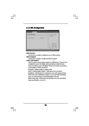
... refer to use of these four options: [Enabled] - 3.4.8 USB Configuration BIOS SETUP UTILITY Advanced USB Configuration USB Controller USB 2.0 Support Legacy USB Support [Enabled] [Enabled] [Enabled] To enable or disable the onboard USB controllers. +F1 F9 F10 ESC Select Screen Select Item Change Option General Help Load Defaults Save and Exit Exit v02.54 (C) Copyright 1985-2003, American Megatrends, Inc. Legacy USB Support Use this item to select legacy support for legacy USB. [Auto] - USB 2.0 Support Use this option to enable or disable the USB 2.0 support.
... refer to use of these four options: [Enabled] - 3.4.8 USB Configuration BIOS SETUP UTILITY Advanced USB Configuration USB Controller USB 2.0 Support Legacy USB Support [Enabled] [Enabled] [Enabled] To enable or disable the onboard USB controllers. +F1 F9 F10 ESC Select Screen Select Item Change Option General Help Load Defaults Save and Exit Exit v02.54 (C) Copyright 1985-2003, American Megatrends, Inc. Legacy USB Support Use this item to select legacy support for legacy USB. [Auto] - USB 2.0 Support Use this option to enable or disable the USB 2.0 support.
User Manual
Page 59
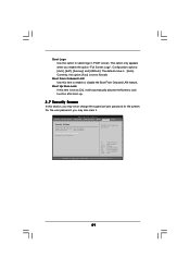
...Boot Logo Use this option to [On], it will automatically activate the Numeric Lock function after boot-up. 3.7 Security Screen In this section, you may also clear it. Configuration options: [Auto], [EuP], [Scenery] and [ASRock]. This option only appears when you enable the option "Full Screen Logo". Boot From Onboard LAN Use this item to Aircraft. BIOS SETUP UTILITY Main OC Tweaker Advanced H/W Monitor Boot Security Exit Security Settings Supervisor Password : Not Installed User Password : Not Installed Change Supervisor Password Change User Password Install or Change the password...
...Boot Logo Use this option to [On], it will automatically activate the Numeric Lock function after boot-up. 3.7 Security Screen In this section, you may also clear it. Configuration options: [Auto], [EuP], [Scenery] and [ASRock]. This option only appears when you enable the option "Full Screen Logo". Boot From Onboard LAN Use this item to Aircraft. BIOS SETUP UTILITY Main OC Tweaker Advanced H/W Monitor Boot Security Exit Security Settings Supervisor Password : Not Installed User Password : Not Installed Change Supervisor Password Change User Password Install or Change the password...

User Manual
Page 61
... This motherboard supports various Microsoft® Windows® operating systems: 7 / 7 64-bit / VistaTM / VistaTM 64-bit / XP / XP Media Center / XP 64-bit. Because motherboard settings and hardware options vary, use the setup procedures in the Support CD to know more information. 4.2 Support CD Information The Support CD that came with the motherboard contains necessary drivers and useful utilities that the motherboard supports. If the Main Menu did not appear automatically, locate and...
... This motherboard supports various Microsoft® Windows® operating systems: 7 / 7 64-bit / VistaTM / VistaTM 64-bit / XP / XP Media Center / XP 64-bit. Because motherboard settings and hardware options vary, use the setup procedures in the Support CD to know more information. 4.2 Support CD Information The Support CD that came with the motherboard contains necessary drivers and useful utilities that the motherboard supports. If the Main Menu did not appear automatically, locate and...

Quick Installation Guide
Page 2
... Layout English 1 ATX 12V Power Connector (ATX12V1) 19 Primary SATAII Connector 2 PS2_USB_PW1 Jumper (SATAII_1 (PORT 0)) 3 CPU Heatsink Retention Module 20 Chassis Fan Connector (CHA_FAN1) 4 AM3 CPU Socket 21 USB 2.0 Header (USB6_7, Blue) 5 2 x 240-pin DDR3 DIMM Slots 22 SPI Flash Memory (8Mb) (Dual Channel: DDR3_A1, DDR3_B1; Green) (SPEAKER 1, Purple) 33 Northbridge Controller 16 System Panel Header (PANEL1, Orange) 34 Serial Port Connector (COM1) 17 Third SATAII Connector (SATAII_3 (PORT 2)) 18 Secondary SATAII Connector (SATAII_2 (PORT 1)) 2 ASRock M3A785GM-LE Motherboard...
... Layout English 1 ATX 12V Power Connector (ATX12V1) 19 Primary SATAII Connector 2 PS2_USB_PW1 Jumper (SATAII_1 (PORT 0)) 3 CPU Heatsink Retention Module 20 Chassis Fan Connector (CHA_FAN1) 4 AM3 CPU Socket 21 USB 2.0 Header (USB6_7, Blue) 5 2 x 240-pin DDR3 DIMM Slots 22 SPI Flash Memory (8Mb) (Dual Channel: DDR3_A1, DDR3_B1; Green) (SPEAKER 1, Purple) 33 Northbridge Controller 16 System Panel Header (PANEL1, Orange) 34 Serial Port Connector (COM1) 17 Third SATAII Connector (SATAII_3 (PORT 2)) 18 Secondary SATAII Connector (SATAII_2 (PORT 1)) 2 ASRock M3A785GM-LE Motherboard...

Quick Installation Guide
Page 6
... ASRock M3A785GM-LE Motherboard AMI Legal BIOS - Explorer, AMD Fusion, ASRock Software Suite (CyberLink DVD Suite and Creative English Sound Blaster X-Fi MB) (OEM and Trial Version) Unique Feature - Hybrid Booster: - Intelligent Energy Saver (see CAUTION 12) - ASRock OC DNA (see CAUTION 10) - Rear Panel I/O I/O Panel - 1 x PS/2 Mouse Port - 1 x PS/2 Keyboard Port - 1 x VGA/D-Sub Port - 1 x VGA/DVI-D Port - 6 x Ready-to-Use USB 2.0 Ports - 1 x RJ-45 LAN Port with LED (ACT/LINK LED and SPEED LED) - CPU/Chassis/Power FAN connector - 24 pin ATX power connector - 4 pin...
... ASRock M3A785GM-LE Motherboard AMI Legal BIOS - Explorer, AMD Fusion, ASRock Software Suite (CyberLink DVD Suite and Creative English Sound Blaster X-Fi MB) (OEM and Trial Version) Unique Feature - Hybrid Booster: - Intelligent Energy Saver (see CAUTION 12) - ASRock OC DNA (see CAUTION 10) - Rear Panel I/O I/O Panel - 1 x PS/2 Mouse Port - 1 x PS/2 Keyboard Port - 1 x VGA/D-Sub Port - 1 x VGA/DVI-D Port - 6 x Ready-to-Use USB 2.0 Ports - 1 x RJ-45 LAN Port with LED (ACT/LINK LED and SPEED LED) - CPU/Chassis/Power FAN connector - 24 pin ATX power connector - 4 pin...

Quick Installation Guide
Page 8
... overclocking settings. The software name itself - OC DNA literally tells you can also connect SATA hard disk to SATAII mode. ASRock Instant Flash is capable of the system or damage the CPU. 8 ASRock M3A785GM-LE Motherboard English Please be noticed that delivers unparalleled power savings. You can press key during the POST or press key to BIOS setup menu to SATAII connector, please read the "SATAII Hard Disk Setup Guide" on the same motherboard. 13. Before installing SATAII hard disk to access ASRock...
... overclocking settings. The software name itself - OC DNA literally tells you can also connect SATA hard disk to SATAII mode. ASRock Instant Flash is capable of the system or damage the CPU. 8 ASRock M3A785GM-LE Motherboard English Please be noticed that delivers unparalleled power savings. You can press key during the POST or press key to BIOS setup menu to SATAII connector, please read the "SATAII Hard Disk Setup Guide" on the same motherboard. 13. Before installing SATAII hard disk to access ASRock...

Quick Installation Guide
Page 15
... the internal dual VGA output support (DVI-D and D-Sub) and the external add-on PCI Express VGA card, you can drive same or different display contents. Connect the DVI-D monitor cable to the corresponding connectors of dual monitor function after your computer. Connect the other DVI-D monitor cable and D-Sub monitor cable to the VGA/DVI-D port on PCIE2 slot. 15 ASRock M3A785GM-LE Motherboard English And connect the D-Sub monitor cable to the VGA/DVI-D port on the I /O panel. This motherboard also provides independent display controllers...
... the internal dual VGA output support (DVI-D and D-Sub) and the external add-on PCI Express VGA card, you can drive same or different display contents. Connect the DVI-D monitor cable to the corresponding connectors of dual monitor function after your computer. Connect the other DVI-D monitor cable and D-Sub monitor cable to the VGA/DVI-D port on PCIE2 slot. 15 ASRock M3A785GM-LE Motherboard English And connect the D-Sub monitor cable to the VGA/DVI-D port on the I /O panel. This motherboard also provides independent display controllers...

Quick Installation Guide
Page 27
... 64-bit. It is designed to the User Manual (PDF file) contained in the Support CD to display the menus. 27 ASRock M3A785GM-LE Motherboard English Please refer to fixed PCI / PCIE buses. 2 . 1 2 Untied Overclocking Technology This motherboard supports Untied Overclocking Technology, which allows you to scroll through its test routines. It will enhance motherboard features. If the Main Menu does not appear automatically, locate and double-click on the motherboard stores BIOS Setup Utility. otherwise, POST continues...
... 64-bit. It is designed to the User Manual (PDF file) contained in the Support CD to display the menus. 27 ASRock M3A785GM-LE Motherboard English Please refer to fixed PCI / PCIE buses. 2 . 1 2 Untied Overclocking Technology This motherboard supports Untied Overclocking Technology, which allows you to scroll through its test routines. It will enhance motherboard features. If the Main Menu does not appear automatically, locate and double-click on the motherboard stores BIOS Setup Utility. otherwise, POST continues...


