User Manual
Page 4
...1 1.1 Package Contents 1 1.2 Specifications 2 1.3 Motherboard Layout 5 1.4 I/O Panel 7 Chapter 2 Installation 9 2.1 Installation of Memory Modules (SO-DIMM) 10 2.2 Expansion Slot (PCI Express Slot) 12 2.3 Jumpers Setup 13 2.4 Onboard Headers and Connectors 14 2.5 M.2 WiFi/BT Module and Intel® CNVi (Integrated WiFi/BT) Installation Guide 17 Chapter 3 Software and Utilities Operation 19 3.1 Installing Drivers 19 3.2 ASRock Live Update & APP Shop 20 3.2.1 UI Overview 20 3.2.2 Apps 21 3.2.3 BIOS & Drivers 24 3.2.4 Setting 25 Chapter 4 UEFI SETUP UTILITY 26...
...1 1.1 Package Contents 1 1.2 Specifications 2 1.3 Motherboard Layout 5 1.4 I/O Panel 7 Chapter 2 Installation 9 2.1 Installation of Memory Modules (SO-DIMM) 10 2.2 Expansion Slot (PCI Express Slot) 12 2.3 Jumpers Setup 13 2.4 Onboard Headers and Connectors 14 2.5 M.2 WiFi/BT Module and Intel® CNVi (Integrated WiFi/BT) Installation Guide 17 Chapter 3 Software and Utilities Operation 19 3.1 Installing Drivers 19 3.2 ASRock Live Update & APP Shop 20 3.2.1 UI Overview 20 3.2.2 Apps 21 3.2.3 BIOS & Drivers 24 3.2.4 Setting 25 Chapter 4 UEFI SETUP UTILITY 26...

User Manual
Page 6
Chapter 4 contains the configuration guide of the motherboard and step-by-step installation guides. Because the motherboard specifications and the BIOS software might be updated, the content of this manual, Chapter 1 and 2 contains the introduction of the BIOS setup. ASRock website http://www.asrock.com. 1.1 Package Contents • ASRock J5040-ITX/J4125-ITX Motherboard (Mini-ITX Form Factor) • ASRock J5040-ITX/J4125-ITX Quick Installation Guide • ASRock J5040-ITX/J4125-ITX Support CD • 2 x Serial ATA (SATA) Data Cables (Optional) • 1 x I/O Panel Shield • ...
Chapter 4 contains the configuration guide of the motherboard and step-by-step installation guides. Because the motherboard specifications and the BIOS software might be updated, the content of this manual, Chapter 1 and 2 contains the introduction of the BIOS setup. ASRock website http://www.asrock.com. 1.1 Package Contents • ASRock J5040-ITX/J4125-ITX Motherboard (Mini-ITX Form Factor) • ASRock J5040-ITX/J4125-ITX Quick Installation Guide • ASRock J5040-ITX/J4125-ITX Support CD • 2 x Serial ATA (SATA) Data Cables (Optional) • 1 x I/O Panel Shield • ...

User Manual
Page 7
... Memory Technology • 2 x DDR4 SO-DIMM Slots * 2GB DRAM per module is required) 2 English 1.2 Specifications Platform • Mini-ITX Form Factor • Solid Capacitor design CPU • Intel® Quad-Core Pentium® Silver Processor J5040 (up to 3.2 GHz) (for J5040-ITX) • Intel® Quad-Core Processor J4125 (up to 1920x1200 @ 60Hz • Supports D-Sub with max. capacity of system memory: 8GB Expansion Slot • 1 x PCI Express 2.0 x1 Slot • 1 x M.2 Socket (Key E), supports type...
... Memory Technology • 2 x DDR4 SO-DIMM Slots * 2GB DRAM per module is required) 2 English 1.2 Specifications Platform • Mini-ITX Form Factor • Solid Capacitor design CPU • Intel® Quad-Core Pentium® Silver Processor J5040 (up to 3.2 GHz) (for J5040-ITX) • Intel® Quad-Core Processor J4125 (up to 1920x1200 @ 60Hz • Supports D-Sub with max. capacity of system memory: 8GB Expansion Slot • 1 x PCI Express 2.0 x1 Slot • 1 x M.2 Socket (Key E), supports type...

User Manual
Page 8
...) • 2 x USB 3.2 Gen1 Ports (Supports ESD Protection) • 1 x RJ-45 LAN Port with LED (ACT/LINK LED and SPEED LED) • HD Audio Jacks: Rear Speaker / Central / Bass / Line in / Front Speaker / Microphone Storage • 2 x SATA3 6.0 Gb/s Connectors, support NCQ, AHCI and Hot Plug • 2 x SATA3 6.0 Gb/s Connectors by ASMedia ASM1061, support NCQ, AHCI and Hot Plug Connector • 1 x COM Port Header • 1 x Chassis Intrusion and Speaker Header • 1 x CPU Fan Connector (3-pin) • 1 x Chassis Fan Connector (3-pin) • 1 x 24 pin ATX Power Connector •...
...) • 2 x USB 3.2 Gen1 Ports (Supports ESD Protection) • 1 x RJ-45 LAN Port with LED (ACT/LINK LED and SPEED LED) • HD Audio Jacks: Rear Speaker / Central / Bass / Line in / Front Speaker / Microphone Storage • 2 x SATA3 6.0 Gb/s Connectors, support NCQ, AHCI and Hot Plug • 2 x SATA3 6.0 Gb/s Connectors by ASMedia ASM1061, support NCQ, AHCI and Hot Plug Connector • 1 x COM Port Header • 1 x Chassis Intrusion and Speaker Header • 1 x CPU Fan Connector (3-pin) • 1 x Chassis Fan Connector (3-pin) • 1 x 24 pin ATX Power Connector •...
User Manual
Page 9
... GUI support • Supports Plug and Play • ACPI 5.0 compliant wake up events • Supports jumperfree • SMBIOS 3.0 support Hardware Monitor • CPU/Chassis temperature sensing • CPU/Chassis Fan Tachometer • CPU/Chassis Quiet Fan (Auto adjust chassis fan speed by CPU temperature) • CPU/Chassis Fan multi-speed control • CASE OPEN detection • Voltage monitoring: +12V, +5V, +3.3V, CPU Vcore OS • Microsoft® Windows® 10 64-bit Certifications • FCC, CE • ErP/EuP ready (ErP/EuP ready power supply is...
... GUI support • Supports Plug and Play • ACPI 5.0 compliant wake up events • Supports jumperfree • SMBIOS 3.0 support Hardware Monitor • CPU/Chassis temperature sensing • CPU/Chassis Fan Tachometer • CPU/Chassis Quiet Fan (Auto adjust chassis fan speed by CPU temperature) • CPU/Chassis Fan multi-speed control • CASE OPEN detection • Voltage monitoring: +12V, +5V, +3.3V, CPU Vcore OS • Microsoft® Windows® 10 64-bit Certifications • FCC, CE • ErP/EuP ready (ErP/EuP ready power supply is...

User Manual
Page 11
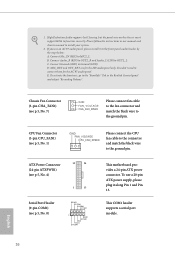
Description 1 CPU Fan Connector (CPU_FAN1) 2 ATX Power Connector (ATXPWR1) 3 System Panel Header (PANEL1) 4 2 x 260-pin DDR4 SO-DIMM Slots (DDR4_A1, DDR4_B1) 5 Chassis Intrusion and Speaker Header (SPK_CI1) 6 Clear CMOS Jumper (CLRMOS1) 7 Chassis Fan Connector (CHA_FAN1) 8 COM Port Header (COM1) 9 USB 2.0 Header (USB_0_1) 10 USB 3.2 Gen1 Header (USB3_0_1) 11 USB 2.0 Header (USB_2) 12 SATA3 Connector (SATA3_1) 13 SATA3 Connector (SATA3_2) 14 SATA3 Connector (SATA3_A2) 15 SATA3 Connector (SATA3_A1) 16 Front Panel Audio Header (HD_AUDIO1) 6 English No.
Description 1 CPU Fan Connector (CPU_FAN1) 2 ATX Power Connector (ATXPWR1) 3 System Panel Header (PANEL1) 4 2 x 260-pin DDR4 SO-DIMM Slots (DDR4_A1, DDR4_B1) 5 Chassis Intrusion and Speaker Header (SPK_CI1) 6 Clear CMOS Jumper (CLRMOS1) 7 Chassis Fan Connector (CHA_FAN1) 8 COM Port Header (COM1) 9 USB 2.0 Header (USB_0_1) 10 USB 3.2 Gen1 Header (USB3_0_1) 11 USB 2.0 Header (USB_2) 12 SATA3 Connector (SATA3_1) 13 SATA3 Connector (SATA3_2) 14 SATA3 Connector (SATA3_A2) 15 SATA3 Connector (SATA3_A1) 16 Front Panel Audio Header (HD_AUDIO1) 6 English No.

User Manual
Page 14
... may damage the motherboard. 9 English Also remember to you install the motherboard, study the configuration of the following precautions before you install motherboard components or change any components, place them on a carpet. Doing so may cause physical injuries to use a grounded wrist strap or touch a safety grounded object before installing or removing the motherboard. J5040-ITX J4125-ITX Chapter 2 Installation This is a Mini-ITX form factor...
... may damage the motherboard. 9 English Also remember to you install the motherboard, study the configuration of the following precautions before you install motherboard components or change any components, place them on a carpet. Doing so may cause physical injuries to use a grounded wrist strap or touch a safety grounded object before installing or removing the motherboard. J5040-ITX J4125-ITX Chapter 2 Installation This is a Mini-ITX form factor...
User Manual
Page 17
... hardware settings for PCI Express x1 lane width cards. Warning: To ensure better graphics compability, the BIOS is unplugged. 2.2 Expansion Slot (PCI Express Slot) There is used for the card before you start the installation. Please read the documentation of the expansion card and make sure that the power supply is switched off or the power cord is set to "boot from Onboard VGA" as default even the user install a VGA card on the motherboard. PCIe slot: PCIE1 (PCIe 2.0 x1 slot) is 1 PCI Express slot on PCIe slot...
... hardware settings for PCI Express x1 lane width cards. Warning: To ensure better graphics compability, the BIOS is unplugged. 2.2 Expansion Slot (PCI Express Slot) There is used for the card before you start the installation. Please read the documentation of the expansion card and make sure that the power supply is switched off or the power cord is set to "boot from Onboard VGA" as default even the user install a VGA card on the motherboard. PCIe slot: PCIE1 (PCIe 2.0 x1 slot) is 1 PCI Express slot on PCIe slot...

User Manual
Page 18
... system password, date, time, and system setup parameters. J5040-ITX J4125-ITX 2.3 Jumpers Setup The illustration shows how jumpers are two ways for you to clear and reset the system parameters to the default setup. When the jumper cap is placed on the pins, the jumper is "Open". *The jumper cap is "Short". Clear CMOS Jumper (CLRCMOS1) (see p.5, No. 6) 2-pin Jumper Short: Clear CMOS Open: Default CLRCMOS1 allows you clear the CMOS, the case open may use a jumper cap to short the pin...
... system password, date, time, and system setup parameters. J5040-ITX J4125-ITX 2.3 Jumpers Setup The illustration shows how jumpers are two ways for you to clear and reset the system parameters to the default setup. When the jumper cap is placed on the pins, the jumper is "Open". *The jumper cap is "Short". Clear CMOS Jumper (CLRCMOS1) (see p.5, No. 6) 2-pin Jumper Short: Clear CMOS Open: Default CLRCMOS1 allows you clear the CMOS, the case open may use a jumper cap to short the pin...
User Manual
Page 21
... follow the instructions in the Realtek Control panel and adjust "Recording Volume". Connect Mic_IN (MIC) to OUT2_L. Connect Ground (GND) to function correctly. B. ATX Power Connector (24-pin ATXPWR1) (see p.5, No. 4) 12 24 1 13 Serial Port Header (9-pin COM1) (see p.5, No. 8) RRXD1 DDTR#1 DDSR#1 CCTS#1 1 RRI#1 RRTS#1 GND TTXD1 DDCD#1 This motherboard provides a 24-pin ATX power connector. If you use a 20-pin ATX power supply, please plug it to the ground pin. High Definition Audio supports Jack...
... follow the instructions in the Realtek Control panel and adjust "Recording Volume". Connect Mic_IN (MIC) to OUT2_L. Connect Ground (GND) to function correctly. B. ATX Power Connector (24-pin ATXPWR1) (see p.5, No. 4) 12 24 1 13 Serial Port Header (9-pin COM1) (see p.5, No. 8) RRXD1 DDTR#1 DDSR#1 CCTS#1 1 RRI#1 RRTS#1 GND TTXD1 DDCD#1 This motherboard provides a 24-pin ATX power connector. If you use a 20-pin ATX power supply, please plug it to the ground pin. High Definition Audio supports Jack...

User Manual
Page 22
J5040-ITX J4125-ITX 2.5 M.2 WiFi/BT Module and Intel® CNVi (Integrated WiFi/BT) Installation Guide The M.2, also known as the Next Generation Form Factor (NGFF), is a small size and versatile card edge connector that the module only fits in one orientation. Please be aware that aims to be used. PCB Length: 3cm Module Type: Type2230 Step 2 Find the nut location to...
J5040-ITX J4125-ITX 2.5 M.2 WiFi/BT Module and Intel® CNVi (Integrated WiFi/BT) Installation Guide The M.2, also known as the Next Generation Form Factor (NGFF), is a small size and versatile card edge connector that the module only fits in one orientation. Please be aware that aims to be used. PCB Length: 3cm Module Type: Type2230 Step 2 Find the nut location to...

User Manual
Page 24
... and listed on a specific item then follow the order from top to bottom to install those required drivers. Click on the support CD driver page. J5040-ITX J4125-ITX Chapter 3 Software and Utilities Operation 3.1 Installing Drivers The Support CD that comes with the motherboard contains necessary drivers and useful utilities that the motherboard supports. If the Main Menu does not appear automatically, locate and double click on the file "ASRSETUP.EXE" in your CD-ROM drive...
... and listed on a specific item then follow the order from top to bottom to install those required drivers. Click on the support CD driver page. J5040-ITX J4125-ITX Chapter 3 Software and Utilities Operation 3.1 Installing Drivers The Support CD that comes with the motherboard contains necessary drivers and useful utilities that the motherboard supports. If the Main Menu does not appear automatically, locate and double click on the file "ASRSETUP.EXE" in your CD-ROM drive...
User Manual
Page 31
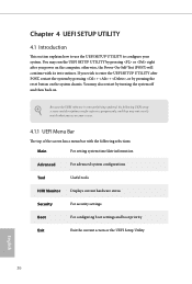
... Power-On-Self-Test (POST) will continue with the following selections: Main For setting system time/date information Advanced For advanced system configurations Tool Useful tools H/W Monitor Displays current hardware status Security For security settings Boot For configuring boot settings and boot priority Exit Exit the current screen or the UEFI Setup Utility English 26 You may not exactly match what you see on the system chassis. If you power...
... Power-On-Self-Test (POST) will continue with the following selections: Main For setting system time/date information Advanced For advanced system configurations Tool Useful tools H/W Monitor Displays current hardware status Security For security settings Boot For configuring boot settings and boot priority Exit Exit the current screen or the UEFI Setup Utility English 26 You may not exactly match what you see on the system chassis. If you power...
User Manual
Page 36
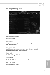
PCIE1 Link Speed Select the link speed for PCIE1. 31 English Onboard HD Audio Enable/disable onboard HD audio. 4.3.2 Chipset Configuration J5040-ITX J4125-ITX Primary Graphics Adapter Select a primary VGA. Share Memory Configure the size of memory that is installed. Set to Auto to enable onboard HD audio and automatically disable it when a sound card is allocated to the integrated graphics processor when the system boots up. Front Panel Enable/disable front panel HD audio. Onboard LAN Enable or disable the onboard network interface controller.
PCIE1 Link Speed Select the link speed for PCIE1. 31 English Onboard HD Audio Enable/disable onboard HD audio. 4.3.2 Chipset Configuration J5040-ITX J4125-ITX Primary Graphics Adapter Select a primary VGA. Share Memory Configure the size of memory that is installed. Set to Auto to enable onboard HD audio and automatically disable it when a sound card is allocated to the integrated graphics processor when the system boots up. Front Panel Enable/disable front panel HD audio. Onboard LAN Enable or disable the onboard network interface controller.
User Manual
Page 40
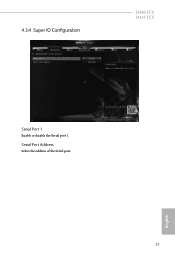
4.3.4 Super IO Configuration J5040-ITX J4125-ITX Serial Port 1 Enable or disable the Serial port 1. Serial Port Address Select the address of the Serial port. 35 English
4.3.4 Super IO Configuration J5040-ITX J4125-ITX Serial Port 1 Enable or disable the Serial port 1. Serial Port Address Select the address of the Serial port. 35 English

User Manual
Page 43
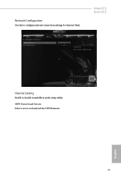
Please setup network configuration before using Internet Flash. *For BIOS backup and recovery purpose, it is recommended to update your USB pen drive before using this function. 38 English Internet Flash ASRock Internet Flash downloads and updates the latest UEFI firmware version from our servers for you. 4.4 Tools Instant Flash Save UEFI files in your USB storage device and run Instant Flash to plug in your UEFI.
Please setup network configuration before using Internet Flash. *For BIOS backup and recovery purpose, it is recommended to update your USB pen drive before using this function. 38 English Internet Flash ASRock Internet Flash downloads and updates the latest UEFI firmware version from our servers for you. 4.4 Tools Instant Flash Save UEFI files in your USB storage device and run Instant Flash to plug in your UEFI.
User Manual
Page 44
UEFI Download Server Select a server to configure internet connection settings for Internet Flash. Network Configuration Use this to download the UEFI firmware. 39 English J5040-ITX J4125-ITX Internet Setting Enable or disable sound effects in the setup utility.
UEFI Download Server Select a server to configure internet connection settings for Internet Flash. Network Configuration Use this to download the UEFI firmware. 39 English J5040-ITX J4125-ITX Internet Setting Enable or disable sound effects in the setup utility.

User Manual
Page 45
Configuration options: [Full On] and [Automatic Mode]. The default value is [Full On]. Configuration options: [Full On], [Automatic Mode] and [Manual]. The default value is [Full On]. Case Open Feature Enable or disable Case Open Feature to set chassis fan 1's speed. Chassis Fan 1 Setting This allows you to monitor the status of the hardware on your system, including the parameters of the CPU temperature, motherboard temperature, fan speed and voltage. 4.5 Hardware Health Event Monitoring Screen This section allows you to set CPU fan 1's speed. CPU Fan 1 Setting This...
Configuration options: [Full On] and [Automatic Mode]. The default value is [Full On]. Configuration options: [Full On], [Automatic Mode] and [Manual]. The default value is [Full On]. Case Open Feature Enable or disable Case Open Feature to set chassis fan 1's speed. Chassis Fan 1 Setting This allows you to monitor the status of the hardware on your system, including the parameters of the CPU temperature, motherboard temperature, fan speed and voltage. 4.5 Hardware Health Event Monitoring Screen This section allows you to set CPU fan 1's speed. CPU Fan 1 Setting This...

User Manual
Page 46
... Password Set or change the settings in the UEFI Setup Utility. Only the administrator has authority to remove the password. Leave it blank and press enter to change the password for the administrator account. Secure Boot Enable to use discrete TPM Module. 41 English Disable this section you may also clear the user password. J5040-ITX J4125-ITX 4.6 Security Screen In this option to support Secure Boot. User Password Set or change the supervisor/user password for the system. Intel(R) Platform Trust Technology Enable/disable...
... Password Set or change the settings in the UEFI Setup Utility. Only the administrator has authority to remove the password. Leave it blank and press enter to change the password for the administrator account. Secure Boot Enable to use discrete TPM Module. 41 English Disable this section you may also clear the user password. J5040-ITX J4125-ITX 4.6 Security Screen In this option to support Secure Boot. User Password Set or change the supervisor/user password for the system. Intel(R) Platform Trust Technology Enable/disable...
User Manual
Page 47
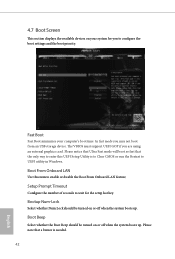
... mode you are using an external graphics card. Boot Beep Select whether the Boot Beep should be turned on or off when the system boots up . Please note that the only way to enter this item to configure the boot settings and the boot priority. The VBIOS must support UEFI GOP if you may not boot from an USB storage device. Setup Prompt Timeout Configure the number of seconds to UEFI utility in Windows. Fast Boot Fast Boot...
... mode you are using an external graphics card. Boot Beep Select whether the Boot Beep should be turned on or off when the system boots up . Please note that the only way to enter this item to configure the boot settings and the boot priority. The VBIOS must support UEFI GOP if you may not boot from an USB storage device. Setup Prompt Timeout Configure the number of seconds to UEFI utility in Windows. Fast Boot Fast Boot...


