User Manual
Page 3
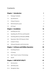
... Specifications 2 1.3 Unique Features 6 1.4 Motherboard Layout 9 1.5 I/O Panel 13 Chapter 2 Installation 16 2.1 Installing the CPU 17 2.2 Installing the CPU Fan and Heatsink 20 2.3 Installing Memory Modules (DIMM) 21 2.4 Expansion Slots (PCI Express Slots) 23 2.5 Jumpers Setup 24 2.6 Onboard Headers and Connectors 25 Chapter 3 Software and Utilities Operation 30 3.1 Installing Drivers 30 3.2 A-Tuning 31 3.3 Intel® Smart Connect Technology 34 3.4 Start8 38 Chapter 4 UEFI SETUP UTILITY 41 4.1 Introduction 41 4.1.1 UEFI Menu Bar 41 4.1.2 Navigation Keys...
... Specifications 2 1.3 Unique Features 6 1.4 Motherboard Layout 9 1.5 I/O Panel 13 Chapter 2 Installation 16 2.1 Installing the CPU 17 2.2 Installing the CPU Fan and Heatsink 20 2.3 Installing Memory Modules (DIMM) 21 2.4 Expansion Slots (PCI Express Slots) 23 2.5 Jumpers Setup 24 2.6 Onboard Headers and Connectors 25 Chapter 3 Software and Utilities Operation 30 3.1 Installing Drivers 30 3.2 A-Tuning 31 3.3 Intel® Smart Connect Technology 34 3.4 Start8 38 Chapter 4 UEFI SETUP UTILITY 41 4.1 Introduction 41 4.1.1 UEFI Menu Bar 41 4.1.2 Navigation Keys...
User Manual
Page 5
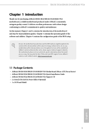
.... In this motherboard, please visit our website for purchasing ASRock H81M-HG4/H81M-DG4/H81M-VG4 motherboard, a reliable motherboard produced under ASRock's consistently stringent quality control. Chapter 3 contains the operation guide of the BIOS setup. ASRock website http://www.asrock.com. 1.1 Package Contents • ASRock H81M-HG4/H81M-DG4/H81M-VG4 Motherboard (Micro ATX Form Factor) • ASRock H81M-HG4/H81M-DG4/H81M-VG4 Quick Installation Guide • ASRock H81M-HG4/H81M-DG4/H81M-VG4 Support CD • 2 x Serial ATA (SATA) Data Cables (Optional) • 1 x I/O Panel Shield...
.... In this motherboard, please visit our website for purchasing ASRock H81M-HG4/H81M-DG4/H81M-VG4 motherboard, a reliable motherboard produced under ASRock's consistently stringent quality control. Chapter 3 contains the operation guide of the BIOS setup. ASRock website http://www.asrock.com. 1.1 Package Contents • ASRock H81M-HG4/H81M-DG4/H81M-VG4 Motherboard (Micro ATX Form Factor) • ASRock H81M-HG4/H81M-DG4/H81M-VG4 Quick Installation Guide • ASRock H81M-HG4/H81M-DG4/H81M-VG4 Support CD • 2 x Serial ATA (SATA) Data Cables (Optional) • 1 x I/O Panel Shield...
User Manual
Page 8
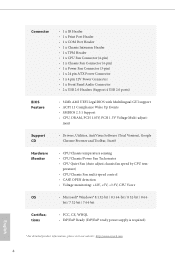
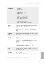
... 24 pin ATX Power Connector • 1 x 4 pin 12V Power Connector • 1 x Front Panel Audio Connector • 2 x USB 2.0 Headers (Support 4 USB 2.0 ports) BIOS Feature • 32Mb AMI UEFI Legal BIOS with Multilingual GUI support • ACPI 1.1 Compliance Wake Up Events • SMBIOS 2.3.1 Support • CPU, DRAM, PCH 1.05V, PCH 1.5V Voltage Multi-adjust- perature) • CPU/Chassis Fan multi-speed control • CASE OPEN detection • Voltage monitoring: +12V, +5V, +3.3V, CPU Vcore OS • Microsoft® Windows® 8.1 32-bit / 8.1 64-bit / 8 32-bit / 8 64- bit...
... 24 pin ATX Power Connector • 1 x 4 pin 12V Power Connector • 1 x Front Panel Audio Connector • 2 x USB 2.0 Headers (Support 4 USB 2.0 ports) BIOS Feature • 32Mb AMI UEFI Legal BIOS with Multilingual GUI support • ACPI 1.1 Compliance Wake Up Events • SMBIOS 2.3.1 Support • CPU, DRAM, PCH 1.05V, PCH 1.5V Voltage Multi-adjust- perature) • CPU/Chassis Fan multi-speed control • CASE OPEN detection • Voltage monitoring: +12V, +5V, +3.3V, CPU Vcore OS • Microsoft® Windows® 8.1 32-bit / 8.1 64-bit / 8 32-bit / 8 64- bit...
User Manual
Page 10
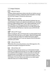
... the USB flash drive or hard drive must use FAT32/16/12 file system. ASRock APP Charger allows you to quickly charge many Apple devices simultaneously and even supports continuous charging when your iPhone/iPad/iPod Touch charge up to the list. ASRock XFast LAN ASRock XFast LAN provides faster internet access, which data streams you to update the system BIOS in Flash ROM. 1.3 Unique Features ASRock A-Tuning A-Tuning is a BIOS flash utility embedded...
... the USB flash drive or hard drive must use FAT32/16/12 file system. ASRock APP Charger allows you to quickly charge many Apple devices simultaneously and even supports continuous charging when your iPhone/iPad/iPod Touch charge up to the list. ASRock XFast LAN ASRock XFast LAN provides faster internet access, which data streams you to update the system BIOS in Flash ROM. 1.3 Unique Features ASRock A-Tuning A-Tuning is a BIOS flash utility embedded...
User Manual
Page 11
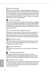
... restrict internet access at specified times via an USB storage device, then downloads and installs the other users. ASRock Internet Flash ASRock Internet Flash downloads and updates the latest UEFI firmware version from our support CD, Easy Driver Installer is a handy tool in the UEFI that installs the LAN driver to your system via OMG. When enabling Dehumidifier Function, the computer will automatically finish the BIOS update procedure after entering S4/S5 state. You may prevent motherboard damages...
... restrict internet access at specified times via an USB storage device, then downloads and installs the other users. ASRock Internet Flash ASRock Internet Flash downloads and updates the latest UEFI firmware version from our support CD, Easy Driver Installer is a handy tool in the UEFI that installs the LAN driver to your system via OMG. When enabling Dehumidifier Function, the computer will automatically finish the BIOS update procedure after entering S4/S5 state. You may prevent motherboard damages...
User Manual
Page 12
... in the BIOS, the Power/LAN LEDs will enter the UEFI directly after you a better sleeping environment by extinguishing the unessential LEDs. The lightning boot up to access the UEFI setup. Why should we even bother memorizing those foot long passwords? Just plug in the USB Key and let your user experience and behavior. Configure up speed makes it takes less than 1.5 seconds to logon to windows automatically! ASRock FAN-Tastic Tuning ASRock FAN-Tastic...
... in the BIOS, the Power/LAN LEDs will enter the UEFI directly after you a better sleeping environment by extinguishing the unessential LEDs. The lightning boot up to access the UEFI setup. Why should we even bother memorizing those foot long passwords? Just plug in the USB Key and let your user experience and behavior. Configure up speed makes it takes less than 1.5 seconds to logon to windows automatically! ASRock FAN-Tastic Tuning ASRock FAN-Tastic...
User Manual
Page 13
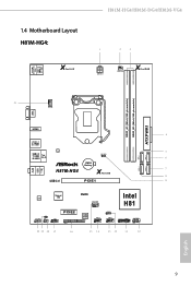
USB 2.0 T: USB0 B: USB1 PS2 Keyboard /Mouse 1.4 Motherboard Layout H81M-HG4: X Fast LAN H81M-HG4/H81M-DG4/H81M-VG4 1 2 3 ATX12V1 PWR_FAN1 X Fast RAM DDR3_A1 (64 bit, 240-pin module) DDR3_B1 (64 bit, 240-pin module) ATXPWR1 21 CPU_FAN1 VGA1 Top: LINE IN Center: FRONT Bottom: MIC IN HDMI1 4 USB 3.0 T: USB0 B: USB1 LAN 5 USB 2.0 CLRCMOS1 T: USB2 Top: RJ-45 1 B: USB3 SATA_3 SATA_2 6 CMOS Battery SATA_1 SATA_0 7 H81M-HG4 X Fast USB 8 USB 3.0 PCIE1 9 Audio CODEC Super I/O RoHS CHA_FAN1 Intel H81...
USB 2.0 T: USB0 B: USB1 PS2 Keyboard /Mouse 1.4 Motherboard Layout H81M-HG4: X Fast LAN H81M-HG4/H81M-DG4/H81M-VG4 1 2 3 ATX12V1 PWR_FAN1 X Fast RAM DDR3_A1 (64 bit, 240-pin module) DDR3_B1 (64 bit, 240-pin module) ATXPWR1 21 CPU_FAN1 VGA1 Top: LINE IN Center: FRONT Bottom: MIC IN HDMI1 4 USB 3.0 T: USB0 B: USB1 LAN 5 USB 2.0 CLRCMOS1 T: USB2 Top: RJ-45 1 B: USB3 SATA_3 SATA_2 6 CMOS Battery SATA_1 SATA_0 7 H81M-HG4 X Fast USB 8 USB 3.0 PCIE1 9 Audio CODEC Super I/O RoHS CHA_FAN1 Intel H81...
User Manual
Page 16
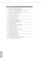
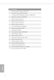
...2 Power Fan Connector (PWR_FAN1) 3 2 x 240-pin DDR3 DIMM Slots (DDR3_A1, DDR3_B1) 4 ATX Power Connector (ATXPWR1) 5 SATA2 Connector (SATA_3) 6 SATA2 Connector (SATA_2) 7 SATA3 Connector (SATA_0) 8 SATA3 Connector (SATA_1) 9 Clear CMOS Jumper (CLRCMOS1) 10 System Panel Header (PANEL1) 11 TPM Header (TPMS1) 12 Chassis Speaker Header (SPEAKER1) 13 USB 2.0 Header (USB6_7) 14 USB 2.0 Header (USB4_5) 15 Chassis Fan Connector (CHA_FAN1) 16 Print Port Header (LPT1) 17 COM Port Header (COM1) 18 Infrared Module Header (IR1) 19 Chassis Intrusion Header (CI1) 20 Front Panel Audio Header (HD_AUDIO1) 21 CPU...
...2 Power Fan Connector (PWR_FAN1) 3 2 x 240-pin DDR3 DIMM Slots (DDR3_A1, DDR3_B1) 4 ATX Power Connector (ATXPWR1) 5 SATA2 Connector (SATA_3) 6 SATA2 Connector (SATA_2) 7 SATA3 Connector (SATA_0) 8 SATA3 Connector (SATA_1) 9 Clear CMOS Jumper (CLRCMOS1) 10 System Panel Header (PANEL1) 11 TPM Header (TPMS1) 12 Chassis Speaker Header (SPEAKER1) 13 USB 2.0 Header (USB6_7) 14 USB 2.0 Header (USB4_5) 15 Chassis Fan Connector (CHA_FAN1) 16 Print Port Header (LPT1) 17 COM Port Header (COM1) 18 Infrared Module Header (IR1) 19 Chassis Intrusion Header (CI1) 20 Front Panel Audio Header (HD_AUDIO1) 21 CPU...
User Manual
Page 28
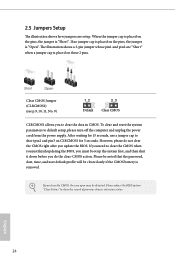
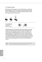
... clear the record of previous chassis intrusion status. Please be noted that the password, date, time, and user default profile will be detected. English 24 After waiting for 15 seconds, use a jumper cap to clear the data in CMOS. If you update the BIOS. Please adjust the BIOS option "Clear Status" to default setup, please turn off the computer and unplug the power cord from the power supply. When the jumper...
... clear the record of previous chassis intrusion status. Please be noted that the password, date, time, and user default profile will be detected. English 24 After waiting for 15 seconds, use a jumper cap to clear the data in CMOS. If you update the BIOS. Please adjust the BIOS option "Clear Status" to default setup, please turn off the computer and unplug the power cord from the power supply. When the jumper...

User Manual
Page 34
... auto-detected and listed on the support CD driver page. "KB2720599": http://support.microsoft.com/kb/2720599/en-us 30 English Therefore, the drivers you install can work properly. To improve Windows 7 compatibility, please download and install the following hot fix provided by Microsoft. Utilities Menu The Utilities Menu shows the application software that enhance the motherboard's features. If the Main Menu does not appear automatically, locate and double click on a specific...
... auto-detected and listed on the support CD driver page. "KB2720599": http://support.microsoft.com/kb/2720599/en-us 30 English Therefore, the drivers you install can work properly. To improve Windows 7 compatibility, please download and install the following hot fix provided by Microsoft. Utilities Menu The Utilities Menu shows the application software that enhance the motherboard's features. If the Main Menu does not appear automatically, locate and double click on a specific...
User Manual
Page 38
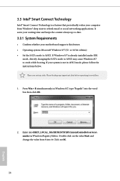
... avoid loss. 1. Double click on OK. 34 English 3.3 Intel® Smart Connect Technology Intel® Smart Connect Technology is not in Windows Registry Editor. or 64-bit edition) • Set the SATA mode to crash while booting. If Windows 8/7 is already installed under IDE mode, directly changing the SATA mode to AHCI may cause Windows 8/7 to AHCI. Click on the value Start and change the value from Windows® sleep state to refresh email or social...
... avoid loss. 1. Double click on OK. 34 English 3.3 Intel® Smart Connect Technology Intel® Smart Connect Technology is not in Windows Registry Editor. or 64-bit edition) • Set the SATA mode to crash while booting. If Windows 8/7 is already installed under IDE mode, directly changing the SATA mode to AHCI may cause Windows 8/7 to AHCI. Click on the value Start and change the value from Windows® sleep state to refresh email or social...
User Manual
Page 45
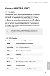
... chassis. Because the UEFI software is a blend of the screen has a menu bar with its test routines. This section explains how to use the UEFI Setup Utility to enter the UEFI Setup Utility after you power on your system. H81M-HG4/H81M-DG4/H81M-VG4 Chapter 4 UEFI SETUP UTILITY 4.1 Introduction ASRock Interactive UEFI is constantly being updated, the following selections: Main For setting system time/date information OC Tweaker For overclocking configurations Advanced For advanced system configurations Tool Useful tools H/W Monitor Displays...
... chassis. Because the UEFI software is a blend of the screen has a menu bar with its test routines. This section explains how to use the UEFI Setup Utility to enter the UEFI Setup Utility after you power on your system. H81M-HG4/H81M-DG4/H81M-VG4 Chapter 4 UEFI SETUP UTILITY 4.1 Introduction ASRock Interactive UEFI is constantly being updated, the following selections: Main For setting system time/date information OC Tweaker For overclocking configurations Advanced For advanced system configurations Tool Useful tools H/W Monitor Displays...
User Manual
Page 60
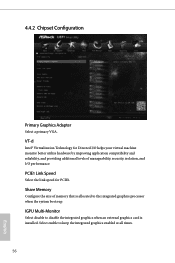
...® Virtualization Technology for PCIE1. PCIE1 Link Speed Select the link speed for Directed I /O performance. Share Memory Configure the size of manageability, security, isolation, and I /O helps your virtual machine monitor better utilize hardware by improving application compatibility and reliability, and providing additional levels of memory that is installed. 4.4.2 Chipset Configuration Primary Graphics Adapter Select a primary VGA. IGPU Multi-Monitor Select disable to disable the integrated graphics when an external graphics card is allocated...
...® Virtualization Technology for PCIE1. PCIE1 Link Speed Select the link speed for Directed I /O performance. Share Memory Configure the size of manageability, security, isolation, and I /O helps your virtual machine monitor better utilize hardware by improving application compatibility and reliability, and providing additional levels of memory that is installed. 4.4.2 Chipset Configuration Primary Graphics Adapter Select a primary VGA. IGPU Multi-Monitor Select disable to disable the integrated graphics when an external graphics card is allocated...
User Manual
Page 61
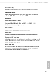
... Standby Power down . If [Power Off] is idle for lower power consumption. Front Panel Enable/disable front panel HD audio. Onboard HDMI HD Audio (Only for H81M-HG4/H81M-DG4) Enable audio for power saving when the computer is on AC/Power Loss Select the power state after a power failure. Good Night LED By enabling Good Night LED, the Power/LAN LEDs will be switched off the Power and Keyboard LEDs when the system enters into Standby/Hibernation mode. 57 English Deep Sleep Configure deep sleep mode...
... Standby Power down . If [Power Off] is idle for lower power consumption. Front Panel Enable/disable front panel HD audio. Onboard HDMI HD Audio (Only for H81M-HG4/H81M-DG4) Enable audio for power saving when the computer is on AC/Power Loss Select the power state after a power failure. Good Night LED By enabling Good Night LED, the Power/LAN LEDs will be switched off the Power and Keyboard LEDs when the system enters into Standby/Hibernation mode. 57 English Deep Sleep Configure deep sleep mode...
User Manual
Page 69
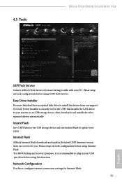
... trouble with your UEFI. Please setup network configuration before using Internet Flash. *For BIOS backup and recovery purpose, it is a handy tool in the UEFI that don't have an optical disk drive to install the drivers from our servers for Internet Flash. 65 English 4.5 Tools H81M-HG4/H81M-DG4/H81M-VG4 UEFI Tech Service Contact ASRock Tech Service if you . Network Configuration Use this function. Easy Driver Installer For users that installs the LAN driver to your system via an USB storage device, then downloads and installs...
... trouble with your UEFI. Please setup network configuration before using Internet Flash. *For BIOS backup and recovery purpose, it is a handy tool in the UEFI that don't have an optical disk drive to install the drivers from our servers for Internet Flash. 65 English 4.5 Tools H81M-HG4/H81M-DG4/H81M-VG4 UEFI Tech Service Contact ASRock Tech Service if you . Network Configuration Use this function. Easy Driver Installer For users that installs the LAN driver to your system via an USB storage device, then downloads and installs...
Quick Installation Guide
Page 5
...2 Power Fan Connector (PWR_FAN1) 3 2 x 240-pin DDR3 DIMM Slots (DDR3_A1, DDR3_B1) 4 ATX Power Connector (ATXPWR1) 5 SATA2 Connector (SATA_3) 6 SATA2 Connector (SATA_2) 7 SATA3 Connector (SATA_0) 8 SATA3 Connector (SATA_1) 9 Clear CMOS Jumper (CLRCMOS1) 10 System Panel Header (PANEL1) 11 TPM Header (TPMS1) 12 Chassis Speaker Header (SPEAKER1) 13 USB 2.0 Header (USB6_7) 14 USB 2.0 Header (USB4_5) 15 Chassis Fan Connector (CHA_FAN1) 16 Print Port Header (LPT1) 17 COM Port Header (COM1) 18 Infrared Module Header (IR1) 19 Chassis Intrusion Header (CI1) 20 Front Panel Audio Header (HD_AUDIO1) 21 CPU...
...2 Power Fan Connector (PWR_FAN1) 3 2 x 240-pin DDR3 DIMM Slots (DDR3_A1, DDR3_B1) 4 ATX Power Connector (ATXPWR1) 5 SATA2 Connector (SATA_3) 6 SATA2 Connector (SATA_2) 7 SATA3 Connector (SATA_0) 8 SATA3 Connector (SATA_1) 9 Clear CMOS Jumper (CLRCMOS1) 10 System Panel Header (PANEL1) 11 TPM Header (TPMS1) 12 Chassis Speaker Header (SPEAKER1) 13 USB 2.0 Header (USB6_7) 14 USB 2.0 Header (USB4_5) 15 Chassis Fan Connector (CHA_FAN1) 16 Print Port Header (LPT1) 17 COM Port Header (COM1) 18 Infrared Module Header (IR1) 19 Chassis Intrusion Header (CI1) 20 Front Panel Audio Header (HD_AUDIO1) 21 CPU...
Quick Installation Guide
Page 12
... Print Port Header • 1 x COM Port Header • 1 x Chassis Intrusion Header • 1 x TPM Header • 1 x CPU Fan Connector (4-pin) • 1 x Chassis Fan Connector (4-pin) • 1 x Power Fan Connector (3-pin) • 1 x 24 pin ATX Power Connector • 1 x 4 pin 12V Power Connector • 1 x Front Panel Audio Connector • 2 x USB 2.0 Headers (Support 4 USB 2.0 ports) BIOS Feature • 32Mb AMI UEFI Legal BIOS with Multilingual GUI support • ACPI 1.1 Compliance Wake Up Events • SMBIOS 2.3.1 Support • CPU, DRAM, PCH 1.05V, PCH 1.5V Voltage Multi...
... Print Port Header • 1 x COM Port Header • 1 x Chassis Intrusion Header • 1 x TPM Header • 1 x CPU Fan Connector (4-pin) • 1 x Chassis Fan Connector (4-pin) • 1 x Power Fan Connector (3-pin) • 1 x 24 pin ATX Power Connector • 1 x 4 pin 12V Power Connector • 1 x Front Panel Audio Connector • 2 x USB 2.0 Headers (Support 4 USB 2.0 ports) BIOS Feature • 32Mb AMI UEFI Legal BIOS with Multilingual GUI support • ACPI 1.1 Compliance Wake Up Events • SMBIOS 2.3.1 Support • CPU, DRAM, PCH 1.05V, PCH 1.5V Voltage Multi...
Quick Installation Guide
Page 14
... Apple devices simultaneously and even supports continuous charging when your PC enters into Suspend to your computer. Lower Latency in Game: After setting online game's priority higher, it can watch Youtube HD videos and download simultaneously. H81M-HG4/H81M-DG4/H81M-VG4 1.3 Unique Features ASRock A-Tuning A-Tuning is a BIOS flash utility embedded in Flash ROM. Just save the new BIOS file to RAM (S3), hibernation mode (S4) or power off (S5). LAN...
... Apple devices simultaneously and even supports continuous charging when your PC enters into Suspend to your computer. Lower Latency in Game: After setting online game's priority higher, it can watch Youtube HD videos and download simultaneously. H81M-HG4/H81M-DG4/H81M-VG4 1.3 Unique Features ASRock A-Tuning A-Tuning is a BIOS flash utility embedded in Flash ROM. Just save the new BIOS file to RAM (S3), hibernation mode (S4) or power off (S5). LAN...
Quick Installation Guide
Page 15
... faster. Only USB 2.0 ports support this feature. ASRock Internet Flash ASRock Internet Flash downloads and updates the latest UEFI firmware version from our support CD, Easy Driver Installer is a handy tool in order to your system via OMG. It fully utilizes the memory space that installs the LAN driver to extend their BIOS without fear of accessing your current PC and the devices connected. If power loss occurs during the BIOS updating process, ASRock Crashless BIOS will power on automatically...
... faster. Only USB 2.0 ports support this feature. ASRock Internet Flash ASRock Internet Flash downloads and updates the latest UEFI firmware version from our support CD, Easy Driver Installer is a handy tool in order to your system via OMG. It fully utilizes the memory space that installs the LAN driver to extend their BIOS without fear of accessing your current PC and the devices connected. If power loss occurs during the BIOS updating process, ASRock Crashless BIOS will power on automatically...
Quick Installation Guide
Page 25
... the power supply. 2.5 Jumpers Setup The illustration shows how jumpers are "Short" when a jumper cap is "Short". If you to short pin2 and pin3 on these 2 pins. If no jumper cap is placed on the pins, the jumper is removed. To clear and reset the system parameters to clear the record of previous chassis intrusion status. Please be noted that the password, date, time, and user default profile will be detected. Clear CMOS Jumper...
... the power supply. 2.5 Jumpers Setup The illustration shows how jumpers are "Short" when a jumper cap is "Short". If you to short pin2 and pin3 on these 2 pins. If no jumper cap is placed on the pins, the jumper is removed. To clear and reset the system parameters to clear the record of previous chassis intrusion status. Please be noted that the password, date, time, and user default profile will be detected. Clear CMOS Jumper...


