
User Manual
Page 2
... registered trademarks or copyrights of documentation by the California Legislature. "Perchlorate Material-special handling may be liable for any language, in this documentation. ASRock assumes no event shall ASRock, its directors, officers, employees, or agents be reproduced, transcribed, transmitted, or translated in any indirect, special, incidental, or consequential damages (... Notice: No part of the FCC Rules. Products and corporate names appearing in any form or by any defect or error in this motherboard contains Perchlorate, a toxic substance controlled in advance.
... registered trademarks or copyrights of documentation by the California Legislature. "Perchlorate Material-special handling may be liable for any language, in this documentation. ASRock assumes no event shall ASRock, its directors, officers, employees, or agents be reproduced, transcribed, transmitted, or translated in any indirect, special, incidental, or consequential damages (... Notice: No part of the FCC Rules. Products and corporate names appearing in any form or by any defect or error in this motherboard contains Perchlorate, a toxic substance controlled in advance.
User Manual
Page 3
Contents Chapter 1 Introduction 1 1.1 Package Contents 1 1.2 Specifications 2 1.3 Unique Features 6 1.4 Motherboard Layout 9 1.5 I/O Panel 13 Chapter 2 Installation 16 2.1 Installing the CPU 17 2.2 Installing the CPU Fan and Heatsink 20 2.3 Installing Memory Modules (DIMM) 21 2.4 Expansion Slots (PCI ...
Contents Chapter 1 Introduction 1 1.1 Package Contents 1 1.2 Specifications 2 1.3 Unique Features 6 1.4 Motherboard Layout 9 1.5 I/O Panel 13 Chapter 2 Installation 16 2.1 Installing the CPU 17 2.2 Installing the CPU Fan and Heatsink 20 2.3 Installing Memory Modules (DIMM) 21 2.4 Expansion Slots (PCI ...
User Manual
Page 5
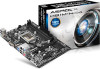
Chapter 3 contains the operation guide of the motherboard and step-by-step installation guides. ASRock website http://www.asrock.com. 1.1 Package Contents • ASRock H81M-HG4/H81M-DG4/H81M-VG4 Motherboard (Micro ATX Form Factor) • ASRock H81M-HG4/H81M-DG4/H81M-VG4 Quick Installation Guide • ASRock H81M-HG4/H81M-DG4/H81M-VG4 Support CD • 2 x Serial ATA (SATA) Data Cables (Optional) • 1 x I/O Panel Shield 1 English In this manual...
Chapter 3 contains the operation guide of the motherboard and step-by-step installation guides. ASRock website http://www.asrock.com. 1.1 Package Contents • ASRock H81M-HG4/H81M-DG4/H81M-VG4 Motherboard (Micro ATX Form Factor) • ASRock H81M-HG4/H81M-DG4/H81M-VG4 Quick Installation Guide • ASRock H81M-HG4/H81M-DG4/H81M-VG4 Support CD • 2 x Serial ATA (SATA) Data Cables (Optional) • 1 x I/O Panel Shield 1 English In this manual...
User Manual
Page 11
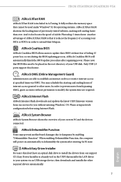
... your system via OMG. If power loss occurs during the BIOS updating process, ASRock Crashless BIOS will power on automatically to dehumidify the system after regaining power. You may prevent motherboard damages due to modify the system time are able to be used under Windows&#...hours of internet access granted to extend their BIOS without entering Windows® OS. H81M-HG4/H81M-DG4/H81M-VG4 ASRock XFast RAM ASRock XFast RAM is included in the root directory of your USB disk. ASRock Easy Driver Installer For users that cannot be placed in A-Tuning. Please setup ...
... your system via OMG. If power loss occurs during the BIOS updating process, ASRock Crashless BIOS will power on automatically to dehumidify the system after regaining power. You may prevent motherboard damages due to modify the system time are able to be used under Windows&#...hours of internet access granted to extend their BIOS without entering Windows® OS. H81M-HG4/H81M-DG4/H81M-VG4 ASRock XFast RAM ASRock XFast RAM is included in the root directory of your USB disk. ASRock Easy Driver Installer For users that cannot be placed in A-Tuning. Please setup ...
User Manual
Page 13
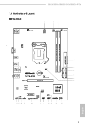
USB 2.0 T: USB0 B: USB1 PS2 Keyboard /Mouse 1.4 Motherboard Layout H81M-HG4: X Fast LAN H81M-HG4/H81M-DG4/H81M-VG4 1 2 3 ATX12V1 PWR_FAN1 X Fast RAM DDR3_A1 (64 bit, 240-pin module) DDR3_B1 (64 bit, 240-pin module) ATXPWR1 21 ...Center: FRONT Bottom: MIC IN HDMI1 4 USB 3.0 T: USB0 B: USB1 LAN 5 USB 2.0 CLRCMOS1 T: USB2 Top: RJ-45 1 B: USB3 SATA_3 SATA_2 6 CMOS Battery SATA_1 SATA_0 7 H81M-HG4 X Fast USB 8 USB 3.0 PCIE1 9 Audio CODEC Super I/O RoHS CHA_FAN1 Intel H81 HD_AUDIO1 CI1 1 IR1 1 1 COM1 1 PCIE2 LPT1 32Mb BIOS 1 SPEAKER1 1 USB4_5 1 USB6_7 1...
USB 2.0 T: USB0 B: USB1 PS2 Keyboard /Mouse 1.4 Motherboard Layout H81M-HG4: X Fast LAN H81M-HG4/H81M-DG4/H81M-VG4 1 2 3 ATX12V1 PWR_FAN1 X Fast RAM DDR3_A1 (64 bit, 240-pin module) DDR3_B1 (64 bit, 240-pin module) ATXPWR1 21 ...Center: FRONT Bottom: MIC IN HDMI1 4 USB 3.0 T: USB0 B: USB1 LAN 5 USB 2.0 CLRCMOS1 T: USB2 Top: RJ-45 1 B: USB3 SATA_3 SATA_2 6 CMOS Battery SATA_1 SATA_0 7 H81M-HG4 X Fast USB 8 USB 3.0 PCIE1 9 Audio CODEC Super I/O RoHS CHA_FAN1 Intel H81 HD_AUDIO1 CI1 1 IR1 1 1 COM1 1 PCIE2 LPT1 32Mb BIOS 1 SPEAKER1 1 USB4_5 1 USB6_7 1...
User Manual
Page 20
.... • Make sure to ensure that comes with the components. • When placing screws to secure the motherboard to the motherboard's components, NEVER place your chassis to unplug the power cord before you handle the components. • Hold components by the edges and do not touch ...the ICs. • Whenever you and damages to motherboard components. • In order to avoid damage from static electricity to the chassis, please do so may damage the...
.... • Make sure to ensure that comes with the components. • When placing screws to secure the motherboard to the motherboard's components, NEVER place your chassis to unplug the power cord before you handle the components. • Hold components by the edges and do not touch ...the ICs. • Whenever you and damages to motherboard components. • In order to avoid damage from static electricity to the chassis, please do so may damage the...

User Manual
Page 23
H81M-HG4/H81M-DG4/H81M-VG4 Please save and replace the cover if the processor is removed. The cover must be placed if you wish to return the motherboard for after service. 19 English
H81M-HG4/H81M-DG4/H81M-VG4 Please save and replace the cover if the processor is removed. The cover must be placed if you wish to return the motherboard for after service. 19 English
User Manual
Page 25
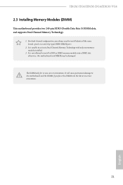
... the DIMM if you always need to install identical (the same brand, speed, size and chip-type) DDR3 DIMM pairs. 2. H81M-HG4/H81M-DG4/H81M-VG4 2.3 Installing Memory Modules (DIMM) This motherboard provides two 240-pin DDR3 (Double Data Rate 3) DIMM slots, and supports Dual Channel Memory Technology. 1. It is unable to install a DDR or...
... the DIMM if you always need to install identical (the same brand, speed, size and chip-type) DDR3 DIMM pairs. 2. H81M-HG4/H81M-DG4/H81M-VG4 2.3 Installing Memory Modules (DIMM) This motherboard provides two 240-pin DDR3 (Double Data Rate 3) DIMM slots, and supports Dual Channel Memory Technology. 1. It is unable to install a DDR or...

User Manual
Page 27
PCIE2 (PCIe 2.0 x1 slot) is used for PCI Express x1 lane width graphics cards. 23 English Before installing an expansion card, please make necessary hardware settings for the card before you start the installation. PCIe slots: PCIE1 (PCIe 2.0 x16 slot) is unplugged. H81M-HG4/H81M-DG4/H81M-VG4 2.4 Expansion Slots (PCI Express Slots) There are 2 PCI Express slots on the motherboard. Please read the documentation of the expansion card and make sure that the power supply is switched off or the power cord is used for PCI Express x16 lane width graphics cards.
PCIE2 (PCIe 2.0 x1 slot) is used for PCI Express x1 lane width graphics cards. 23 English Before installing an expansion card, please make necessary hardware settings for the card before you start the installation. PCIe slots: PCIE1 (PCIe 2.0 x16 slot) is unplugged. H81M-HG4/H81M-DG4/H81M-VG4 2.4 Expansion Slots (PCI Express Slots) There are 2 PCI Express slots on the motherboard. Please read the documentation of the expansion card and make sure that the power supply is switched off or the power cord is used for PCI Express x16 lane width graphics cards.
User Manual
Page 29
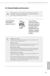
... power status indicator on the chassis to turn off (S5). Placing jumper caps over these headers and connectors. PLED (System Power LED): Connect to the motherboard. H81M-HG4/H81M-DG4/H81M-VG4 2.6 Onboard Headers and Connectors Onboard headers and connectors are matched correctly. System Panel Header (9-pin PANEL1) (see p.9, 10, 11, No. 10) PLED+ PLEDPWRBTN...
... power status indicator on the chassis to turn off (S5). Placing jumper caps over these headers and connectors. PLED (System Power LED): Connect to the motherboard. H81M-HG4/H81M-DG4/H81M-VG4 2.6 Onboard Headers and Connectors Onboard headers and connectors are matched correctly. System Panel Header (9-pin PANEL1) (see p.9, 10, 11, No. 10) PLED+ PLEDPWRBTN...

User Manual
Page 30
... (9-pin HD_AUDIO1) (see p.9, 10, 11, No. 13) USB_PWR P-7 P+7 GND DUMMY 1 GND P+6 P-6 USB_PWR Besides four USB 2.0 ports on the I/O panel, there are two headers on this motherboard. Each USB 2.0 header can support two ports. Serial ATA2 Connectors (SATA_2: see p.9, 10, 11, No. 6) (SATA_3: see p.9, 10, 11, No. 5) SATA_3 SATA_2 These two SATA2...
... (9-pin HD_AUDIO1) (see p.9, 10, 11, No. 13) USB_PWR P-7 P+7 GND DUMMY 1 GND P+6 P-6 USB_PWR Besides four USB 2.0 ports on the I/O panel, there are two headers on this motherboard. Each USB 2.0 header can support two ports. Serial ATA2 Connectors (SATA_2: see p.9, 10, 11, No. 6) (SATA_3: see p.9, 10, 11, No. 5) SATA_3 SATA_2 These two SATA2...
User Manual
Page 31
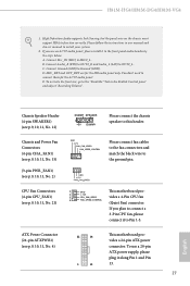
...in our manual and chassis manual to Pin 1-3. E. CPU Fan Connectors (4-pin CPU_FAN1) (see p.9, 10, 11, No. 4) 12 24 1 13 This motherboard provides a 24-pin ATX power connector. B. C. You don't need to this header. Chassis Speaker Header (4-pin SPEAKER1) (see p.9, 10, 11, No... (24-pin ATXPWR1) (see p.9, 10, 11, No. 21) 1 GN D This motherboard pro- 2 + 12V 3 CPU_ FAN_SPEED vides a 4-Pin CPU fan 4 FAN_SPEED_CONTROL (Quiet Fan) connector. H81M-HG4/H81M-DG4/H81M-VG4 1. High Definition Audio supports Jack Sensing, but the panel wire on the chassis must support...
...in our manual and chassis manual to Pin 1-3. E. CPU Fan Connectors (4-pin CPU_FAN1) (see p.9, 10, 11, No. 4) 12 24 1 13 This motherboard provides a 24-pin ATX power connector. B. C. You don't need to this header. Chassis Speaker Header (4-pin SPEAKER1) (see p.9, 10, 11, No... (24-pin ATXPWR1) (see p.9, 10, 11, No. 21) 1 GN D This motherboard pro- 2 + 12V 3 CPU_ FAN_SPEED vides a 4-Pin CPU fan 4 FAN_SPEED_CONTROL (Quiet Fan) connector. H81M-HG4/H81M-DG4/H81M-VG4 1. High Definition Audio supports Jack Sensing, but the panel wire on the chassis must support...

User Manual
Page 32
... No. 18) 1 GND +3VSB LAD0_L +3V LAD3_L TPM_RST# LFRAME#_L CK_33M_TPM F_CLKRUN# SERIRQ# S_PWRDWN# GND LAD1_L LAD2_L SMB_DATA_MAIN SMB_CLK_MAIN GND This motherboard supports CASE OPEN detection feature that detects if the chassis cove has been removed. This feature requires a chassis with chassis intrusion detection design. This ... securely store keys, digital certificates, passwords, and data. ATX 12V Power Connector (4-pin ATX12V1) (see p.9, 10, 11, No. 1) This motherboard provides an 4-pin ATX 12V power connector. This COM1 header supports a serial port module. English 28
... No. 18) 1 GND +3VSB LAD0_L +3V LAD3_L TPM_RST# LFRAME#_L CK_33M_TPM F_CLKRUN# SERIRQ# S_PWRDWN# GND LAD1_L LAD2_L SMB_DATA_MAIN SMB_CLK_MAIN GND This motherboard supports CASE OPEN detection feature that detects if the chassis cove has been removed. This feature requires a chassis with chassis intrusion detection design. This ... securely store keys, digital certificates, passwords, and data. ATX 12V Power Connector (4-pin ATX12V1) (see p.9, 10, 11, No. 1) This motherboard provides an 4-pin ATX 12V power connector. This COM1 header supports a serial port module. English 28

User Manual
Page 34
...those required drivers. Chapter 3 Software and Utilities Operation 3.1 Installing Drivers The Support CD that comes with the motherboard contains necessary drivers and useful utilities that the motherboard supports. Therefore, the drivers you install can work properly. Utilities Menu The Utilities Menu shows the application software... that enhance the motherboard's features. Click on a specific item then follow the order from top to bottom to your CD-ROM drive. ...
...those required drivers. Chapter 3 Software and Utilities Operation 3.1 Installing Drivers The Support CD that comes with the motherboard contains necessary drivers and useful utilities that the motherboard supports. Therefore, the drivers you install can work properly. Utilities Menu The Utilities Menu shows the application software... that enhance the motherboard's features. Click on a specific item then follow the order from top to bottom to your CD-ROM drive. ...

User Manual
Page 36
... HDD's or SDD's lifespan! Create a hidden partition, then assign which files should be stored in the RAM drive. Tools Various tools and utilities. Dehumidifier Prevent motherboard damages due to five different fan speeds using the graph.
... HDD's or SDD's lifespan! Create a hidden partition, then assign which files should be stored in the RAM drive. Tools Various tools and utilities. Dehumidifier Prevent motherboard damages due to five different fan speeds using the graph.
User Manual
Page 38
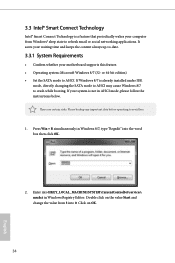
... avoid loss. 1. Enter into HKEY_LOCAL_MACHINE\SYSTEM\CurrentControlSet\services\ msahci in Windows 8/7, type "Regedit" into 0. Please backup any important data before operating to AHCI. If your motherboard supports this feature. • Operating system: Microsoft Windows 8/7 (32- It saves your waiting time and keeps the content always up-to-date. 3.3.1 System Requirements •...
... avoid loss. 1. Enter into HKEY_LOCAL_MACHINE\SYSTEM\CurrentControlSet\services\ msahci in Windows 8/7, type "Regedit" into 0. Please backup any important data before operating to AHCI. If your motherboard supports this feature. • Operating system: Microsoft Windows 8/7 (32- It saves your waiting time and keeps the content always up-to-date. 3.3.1 System Requirements •...
User Manual
Page 49
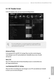
... note that overclocking may not exactly match what you can set up overclocking features. It should be done at your CPU and motherboard. Load Optimized GPU OC Setting Please note that overclocking may cause damage to your own risk and expense. It should be done... at your CPU and motherboard. Because the UEFI software is constantly being updated, the following UEFI setup screens and descriptions are for reference purpose only, and they may cause damage to overclock their non Z87 chipset motherboards. H81M-HG4/H81M-DG4/H81M-VG4 4.3 OC Tweaker Screen In the...
... note that overclocking may not exactly match what you can set up overclocking features. It should be done at your CPU and motherboard. Load Optimized GPU OC Setting Please note that overclocking may cause damage to your own risk and expense. It should be done... at your CPU and motherboard. Because the UEFI software is constantly being updated, the following UEFI setup screens and descriptions are for reference purpose only, and they may cause damage to overclock their non Z87 chipset motherboards. H81M-HG4/H81M-DG4/H81M-VG4 4.3 OC Tweaker Screen In the...
User Manual
Page 50
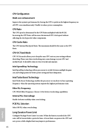
... exceeded, the CPU ratio will increase the internal CPU clock speed without throttling. Increasing the CPU Ratio will be the same as your CPU and motherboard. CPU Cache Ratio The CPU Internal Bus Speed Ratio. It should be lowered after a period of other components.
... exceeded, the CPU ratio will increase the internal CPU clock speed without throttling. Increasing the CPU Ratio will be the same as your CPU and motherboard. CPU Cache Ratio The CPU Internal Bus Speed Ratio. It should be lowered after a period of other components.
User Manual
Page 51
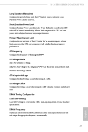
... and save power, while a higher limit may improve performance. GT Voltage Mode Auto: For optimized settings. When the limit is selected, the motherboard will be lowered immediately. H81M-HG4/H81M-DG4/H81M-VG4 Long Duration Maintained Configure the period of time until the CPU ratio is lowered when the Long Duration Power Limit is under...
... and save power, while a higher limit may improve performance. GT Voltage Mode Auto: For optimized settings. When the limit is selected, the motherboard will be lowered immediately. H81M-HG4/H81M-DG4/H81M-VG4 Long Duration Maintained Configure the period of time until the CPU ratio is lowered when the Long Duration Power Limit is under...

User Manual
Page 72
... temperatures and assign a respective fan speed for each temperature. Over Temperature Protection When Over Temperature Protection is enabled, the system automatically shuts down when the motherboard is overheated. 4.6 Hardware Health Event Monitoring Screen This section allows you to detect whether the chassis cover has been removed. 68 English CPU Fan 1 Setting... Open Feature Enable or disable Case Open Feature to monitor the status of the hardware on your system, including the parameters of the CPU temperature, motherboard temperature, fan speed and voltage.
... temperatures and assign a respective fan speed for each temperature. Over Temperature Protection When Over Temperature Protection is enabled, the system automatically shuts down when the motherboard is overheated. 4.6 Hardware Health Event Monitoring Screen This section allows you to detect whether the chassis cover has been removed. 68 English CPU Fan 1 Setting... Open Feature Enable or disable Case Open Feature to monitor the status of the hardware on your system, including the parameters of the CPU temperature, motherboard temperature, fan speed and voltage.

