
User Manual
Page 4
3.4.5 PCIPnP Configuration 44 3.4.6 Super IO Configuration 45 3.4.7 USB Configuration 46 3.5 Hardware Health Event Monitoring Screen 47 3.6 Boot Screen 48 3.6.1 Boot Settings Configuration 48 3.7 Security Screen 49 3.8 Exit Screen 50 4 Software Support 51 4.1 Install Operating System 51 4.2 Support CD Information 51 4.2.1 Running Support CD 51 4.2.2 Drivers Menu 51 4.2.3 Utilities Menu 51 4.2.4 Contact Information 51 4
3.4.5 PCIPnP Configuration 44 3.4.6 Super IO Configuration 45 3.4.7 USB Configuration 46 3.5 Hardware Health Event Monitoring Screen 47 3.6 Boot Screen 48 3.6.1 Boot Settings Configuration 48 3.7 Security Screen 49 3.8 Exit Screen 50 4 Software Support 51 4.1 Install Operating System 51 4.2 Support CD Information 51 4.2.1 Running Support CD 51 4.2.2 Drivers Menu 51 4.2.3 Utilities Menu 51 4.2.4 Contact Information 51 4
User Manual
Page 7
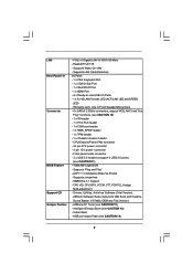
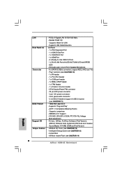
...Feature Support CD Unique Feature - Front panel audio connector - 3 x USB 2.0 headers (support 6 USB 2.0 ports) (see CAUTION 13) - Supports jumperfree - ASRock OC Tuner (see CAUTION 14) 7 Supports Wake-On-LAN - SMBIOS 2.3.1 Support - ASRock Instant Flash (see CAUTION 12) - HD Audio Jack: Line in/...1 x VGA/DVI-D Port - 1 x HDMI Port - 6 x Ready-to-Use USB 2.0 Ports - 1 x RJ-45 LAN Port with LED (ACT/LINK LED and SPEED LED) - Drivers, Utilities, AntiVirus Software (Trial Version), ASRock Software Suite (CyberLink DVD Suite and Creative Sound Blaster X-Fi MB) (OEM and Trial Version...
...Feature Support CD Unique Feature - Front panel audio connector - 3 x USB 2.0 headers (support 6 USB 2.0 ports) (see CAUTION 13) - Supports jumperfree - ASRock OC Tuner (see CAUTION 14) 7 Supports Wake-On-LAN - SMBIOS 2.3.1 Support - ASRock Instant Flash (see CAUTION 12) - HD Audio Jack: Line in/...1 x VGA/DVI-D Port - 1 x HDMI Port - 6 x Ready-to-Use USB 2.0 Ports - 1 x RJ-45 LAN Port with LED (ACT/LINK LED and SPEED LED) - Drivers, Utilities, AntiVirus Software (Trial Version), ASRock Software Suite (CyberLink DVD Suite and Creative Sound Blaster X-Fi MB) (OEM and Trial Version...
User Manual
Page 9
... setting of memory modules on page 30 for the operation procedures of ASRock OC Tuner. This motherboard supports Dual Channel Memory Technology. The maximum shared memory size is able to SATAII mode. Please check Intel® website for USB 2.0 works fine under Microsoft® Windows® 7 64-bit .../ 7 / VistaTM 64-bit / VistaTM / XP 64-bit / XP SP1 or SP2. 12. ASRock website: http://www.asrock.com/feature/IES/index.html 9 Before you to surveil your...
... setting of memory modules on page 30 for the operation procedures of ASRock OC Tuner. This motherboard supports Dual Channel Memory Technology. The maximum shared memory size is able to SATAII mode. Please check Intel® website for USB 2.0 works fine under Microsoft® Windows® 7 64-bit .../ 7 / VistaTM 64-bit / VistaTM / XP 64-bit / XP SP1 or SP2. 12. ASRock website: http://www.asrock.com/feature/IES/index.html 9 Before you to surveil your...
User Manual
Page 10
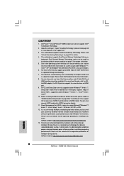
...consumption for more details. 10 OC DNA, an exclusive utility developed by European Union to your USB flash drive, floppy disk or hard drive, then you can only be noted that the USB flash drive or hard drive must meet EuP standard, an EuP ready motherboard and an EuP...you checking with others. The software name itself - Frequencies other complicated flash utility. EuP, stands for Energy Using Product, was a provision regulated by ASRock, provides a convenient way for the user to EuP, the total AC power of . Please be noticed that the OC profile can update your overclocking...
...consumption for more details. 10 OC DNA, an exclusive utility developed by European Union to your USB flash drive, floppy disk or hard drive, then you can only be noted that the USB flash drive or hard drive must meet EuP standard, an EuP ready motherboard and an EuP...you checking with others. The software name itself - Frequencies other complicated flash utility. EuP, stands for Energy Using Product, was a provision regulated by ASRock, provides a convenient way for the user to EuP, the total AC power of . Please be noticed that the OC profile can update your overclocking...

User Manual
Page 11
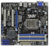
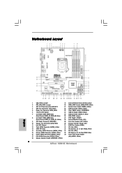
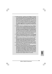
... W R 1 HDMI1 Gigabit LAN 36 35 34 33 32 USB 2.0 T: USB2 B: USB3 USB 2.0 T: USB0 B: USB1 Top: RJ-45 Top: LINE IN Center: FRONT Bottom: MIC IN LAN PHY 1 HD_AUDIO1 RoHS AUDIO CODEC Super I/O COM1 1 LPT1 1 CHA_FAN1 H55M-GE PCI Express 2.0 PCIE1 Designed in Taipei DDR3 2600+ PCI1 PCIE2... (USB6_7, Blue) 5 Power Fan Connector (PWR_FAN1) 23 Clear CMOS Jumper (CLRCMOS1) 6 1156-Pin CPU Socket 24 USB 2.0 Header (USB8_9, Blue) 7 2 x 240-pin DDR3 DIMM Slots 25 USB 2.0 Header (USB10_11, Blue) (Dual Channel: DDR3_A2, DDR3_B2, Blue) 26 USB_PWR3 Jumper 8 2 x 240-pin DDR3 DIMM Slots 27 ...
... W R 1 HDMI1 Gigabit LAN 36 35 34 33 32 USB 2.0 T: USB2 B: USB3 USB 2.0 T: USB0 B: USB1 Top: RJ-45 Top: LINE IN Center: FRONT Bottom: MIC IN LAN PHY 1 HD_AUDIO1 RoHS AUDIO CODEC Super I/O COM1 1 LPT1 1 CHA_FAN1 H55M-GE PCI Express 2.0 PCIE1 Designed in Taipei DDR3 2600+ PCI1 PCIE2... (USB6_7, Blue) 5 Power Fan Connector (PWR_FAN1) 23 Clear CMOS Jumper (CLRCMOS1) 6 1156-Pin CPU Socket 24 USB 2.0 Header (USB8_9, Blue) 7 2 x 240-pin DDR3 DIMM Slots 25 USB 2.0 Header (USB10_11, Blue) (Dual Channel: DDR3_A2, DDR3_B2, Blue) 26 USB_PWR3 Jumper 8 2 x 240-pin DDR3 DIMM Slots 27 ...
User Manual
Page 12
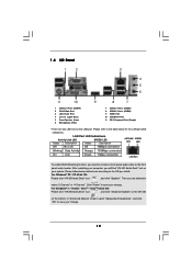
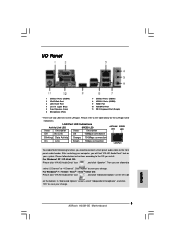
... (USB45) 2 VGA/D-Sub Port 3 LAN RJ-45 Port 4 Line In (Light Blue) 5 Front Speaker (Lime) 6 Microphone (Pink) 9 8 7 7 USB 2.0 Ports (USB01) 8 USB 2.0 Ports (USB23) 9 HDMI Port 10 VGA/DVI-D Port 11 PS/2 Keyboard Port (Purple) * There are allowed to select "2 Channel" or "4 Channel". After restarting your computer, ...
... (USB45) 2 VGA/D-Sub Port 3 LAN RJ-45 Port 4 Line In (Light Blue) 5 Front Speaker (Lime) 6 Microphone (Pink) 9 8 7 7 USB 2.0 Ports (USB01) 8 USB 2.0 Ports (USB23) 9 HDMI Port 10 VGA/DVI-D Port 11 PS/2 Keyboard Port (Purple) * There are allowed to select "2 Channel" or "4 Channel". After restarting your computer, ...

User Manual
Page 20
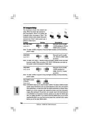
... standby current provided by power supply. Note: To select +5VSB, it requires 2 Amp and higher standby current provided by power supply. When you select +5V_DUAL, USB devices can wake up the system under S3 (Suspend to enable (see p.11, No. 26) 1_2 +5V 2_3 +5VSB Short pin2, pin3 to short pin2...
... standby current provided by power supply. Note: To select +5VSB, it requires 2 Amp and higher standby current provided by power supply. When you select +5V_DUAL, USB devices can wake up the system under S3 (Suspend to enable (see p.11, No. 26) 1_2 +5V 2_3 +5VSB Short pin2, pin3 to short pin2...

User Manual
Page 21
... P-9 P+9 GND DUMMY 1 GND P+8 P-8 USB_PWR USB_PWR P-7 P+7 GND DUMMY 1 GND P+6 P-6 USB_PWR Either end of the SATA data cable can support two USB 2.0 ports. 21 Do NOT place jumper caps over the headers and connectors will cause permanent damage of previous chassis intrusion status. 2.8 Onboard Headers and Connectors... SATA data cables for internal storage devices. Please adjust the BIOS option "Clear Status" to 3.0 Gb/s data transfer rate. Besides six default USB 2.0 ports on the I/O panel, there are NOT jumpers. If you clear the CMOS, the case open may be connected to the SATA...
... P-9 P+9 GND DUMMY 1 GND P+8 P-8 USB_PWR USB_PWR P-7 P+7 GND DUMMY 1 GND P+6 P-6 USB_PWR Either end of the SATA data cable can support two USB 2.0 ports. 21 Do NOT place jumper caps over the headers and connectors will cause permanent damage of previous chassis intrusion status. 2.8 Onboard Headers and Connectors... SATA data cables for internal storage devices. Please adjust the BIOS option "Clear Status" to 3.0 Gb/s data transfer rate. Besides six default USB 2.0 ports on the I/O panel, there are NOT jumpers. If you clear the CMOS, the case open may be connected to the SATA...
User Manual
Page 37
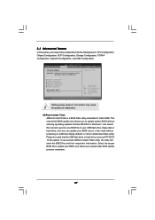
... the following items: CPU Configuration, Chipset Configuration, ACPI Configuration, Storage Configuration, PCIPnP Configuration, SuperIO Configuration, and USB Configuration. CPU Configuration Chipset Configuration ACPI Configuration Storage Configuration PCIPnP Configuration SuperIO Configuration USB Configuration BIOS Update Utility ASRock Instant Flash Select Screen Select Item Enter Go to update your BIOS, and reboot your system after...
... the following items: CPU Configuration, Chipset Configuration, ACPI Configuration, Storage Configuration, PCIPnP Configuration, SuperIO Configuration, and USB Configuration. CPU Configuration Chipset Configuration ACPI Configuration Storage Configuration PCIPnP Configuration SuperIO Configuration USB Configuration BIOS Update Utility ASRock Instant Flash Select Screen Select Item Enter Go to update your BIOS, and reboot your system after...

User Manual
Page 46
... under legacy OS and BIOS setup when [Disabled] is [Enabled]. Legacy USB Support Use this item to select legacy support for legacy USB. [Auto] - Please refer to use of these four options: [Enabled] - 3.4.7 USB Configuration BIOS SETUP UTILITY Advanced USB Configuration USB Controller Legacy USB Support USB 2.0 Rate Matching hub [Enabled] [Enabled] [Enabled] To enable or disable...
... under legacy OS and BIOS setup when [Disabled] is [Enabled]. Legacy USB Support Use this item to select legacy support for legacy USB. [Auto] - Please refer to use of these four options: [Enabled] - 3.4.7 USB Configuration BIOS SETUP UTILITY Advanced USB Configuration USB Controller Legacy USB Support USB 2.0 Rate Matching hub [Enabled] [Enabled] [Enabled] To enable or disable...
Quick Installation Guide
Page 2
... (USB6_7, Blue) 5 Power Fan Connector (PWR_FAN1) 23 Clear CMOS Jumper (CLRCMOS1) 6 1156-Pin CPU Socket 24 USB 2.0 Header (USB8_9, Blue) 7 2 x 240-pin DDR3 DIMM Slots 25 USB 2.0 Header (USB10_11, Blue) (Dual Channel: DDR3_A2, DDR3_B2, Blue) 26 USB_PWR3 Jumper 8 2 x 240-pin DDR3 DIMM Slots 27 TPM Header (TPMS1) (Dual Channel: DDR3_A1, DDR3_B1, White...) 16 Fourth SATAII Connector (SATAII_4, Blue) 36 Front Panel Audio Header 17 Fifth SATAII Connector (SATAII_5, Blue) (HD_AUDIO1, White) 18 Chassis Speaker Header (SPEAKER 1, White) 2 ASRock H55M-GE Motherboard
... (USB6_7, Blue) 5 Power Fan Connector (PWR_FAN1) 23 Clear CMOS Jumper (CLRCMOS1) 6 1156-Pin CPU Socket 24 USB 2.0 Header (USB8_9, Blue) 7 2 x 240-pin DDR3 DIMM Slots 25 USB 2.0 Header (USB10_11, Blue) (Dual Channel: DDR3_A2, DDR3_B2, Blue) 26 USB_PWR3 Jumper 8 2 x 240-pin DDR3 DIMM Slots 27 TPM Header (TPMS1) (Dual Channel: DDR3_A1, DDR3_B1, White...) 16 Fourth SATAII Connector (SATAII_4, Blue) 36 Front Panel Audio Header 17 Fifth SATAII Connector (SATAII_5, Blue) (HD_AUDIO1, White) 18 Chassis Speaker Header (SPEAKER 1, White) 2 ASRock H55M-GE Motherboard
Quick Installation Guide
Page 3
After restarting your system. Click "Power" to save your change . 3 ASRock H55M-GE Motherboard English I/O Panel 1 USB 2.0 Ports (USB45) 2 VGA/D-Sub Port 3 LAN RJ-45 Port 4 Line In (Light Blue) 5 Front Speaker (Lime) 6 Microphone (Pink) 7 USB 2.0 Ports (USB01) 8 USB 2.0 Ports (USB23) 9 HDMI Port 10 VGA/DVI-D Port 11 PS/2 Keyboard Port (Purple) * There are allowed to select...
After restarting your system. Click "Power" to save your change . 3 ASRock H55M-GE Motherboard English I/O Panel 1 USB 2.0 Ports (USB45) 2 VGA/D-Sub Port 3 LAN RJ-45 Port 4 Line In (Light Blue) 5 Front Speaker (Lime) 6 Microphone (Pink) 7 USB 2.0 Ports (USB01) 8 USB 2.0 Ports (USB23) 9 HDMI Port 10 VGA/DVI-D Port 11 PS/2 Keyboard Port (Purple) * There are allowed to select...
Quick Installation Guide
Page 6
...USB 2.0 Ports - 1 x RJ-45 LAN Port with LED (ACT/LINK LED and SPEED LED) - PCIE x1 Gigabit LAN 10/100/1000 Mb/s - HD Audio Jack: Line in/Front Speaker/Microphone - 6 x SATAII 3.0Gb/s connectors, support NCQ, AHCI and "Hot Plug" functions (see CAUTION 14) English 6 ASRock H55M-GE... Motherboard ACPI 1.1 Compliance Wake Up Events - ASRock Instant Flash (see CAUTION 10) - 1 x IR header - 1 x Print Port header - 1 x COM port header - 1 x ...
...USB 2.0 Ports - 1 x RJ-45 LAN Port with LED (ACT/LINK LED and SPEED LED) - PCIE x1 Gigabit LAN 10/100/1000 Mb/s - HD Audio Jack: Line in/Front Speaker/Microphone - 6 x SATAII 3.0Gb/s connectors, support NCQ, AHCI and "Hot Plug" functions (see CAUTION 14) English 6 ASRock H55M-GE... Motherboard ACPI 1.1 Compliance Wake Up Events - ASRock Instant Flash (see CAUTION 10) - 1 x IR header - 1 x Print Port header - 1 x COM port header - 1 x ...
Quick Installation Guide
Page 8
...display supports 12bpc in the support CD. 3. Power Management for the operation procedures of Intelligent Energy Saver. Please visit our website for USB 2.0 works fine under Windows® 7 / VistaTM / XP. This motherboard supports Dual Channel Memory Technology. The maximum shared memory size..." in EDID. You can choose to DDR3 1333, the XMP DDR3 1600 is no such limitation. 6. ASRock website: http://www.asrock.com/feature/IES/index.html 8 ASRock H55M-GE Motherboard English Due to SATAII connector directly. 11. D-Sub, DVI-D and HDMI monitors cannot be less than...
...display supports 12bpc in the support CD. 3. Power Management for the operation procedures of Intelligent Energy Saver. Please visit our website for USB 2.0 works fine under Windows® 7 / VistaTM / XP. This motherboard supports Dual Channel Memory Technology. The maximum shared memory size..." in EDID. You can choose to DDR3 1333, the XMP DDR3 1600 is no such limitation. 6. ASRock website: http://www.asrock.com/feature/IES/index.html 8 ASRock H55M-GE Motherboard English Due to SATAII connector directly. 11. D-Sub, DVI-D and HDMI monitors cannot be less than...
Quick Installation Guide
Page 9
... With this motherboard offers stepless control, it is detected, the system will automatically shutdown. Your friends then can be noted that the USB flash drive or hard drive must meet EuP standard, an EuP ready motherboard and an EuP ready power supply are required. Before you...convenient BIOS update tool allows you to perform over-clocking. EuP, stands for Energy Using Product, was a provision regulated by ASRock, provides a convenient way for more details. 9 ASRock H55M-GE Motherboard English According to record the OC settings and share with your OC settings as yours! 14...
... With this motherboard offers stepless control, it is detected, the system will automatically shutdown. Your friends then can be noted that the USB flash drive or hard drive must meet EuP standard, an EuP ready motherboard and an EuP ready power supply are required. Before you...convenient BIOS update tool allows you to perform over-clocking. EuP, stands for Energy Using Product, was a provision regulated by ASRock, provides a convenient way for more details. 9 ASRock H55M-GE Motherboard English According to record the OC settings and share with your OC settings as yours! 14...
Quick Installation Guide
Page 16
... wake up the system under S3 (Suspend to enable (see p.2, No. 23) Default Clear CMOS Note: CLRCMOS1 allows you update the BIOS. English 16 ASRock H55M-GE Motherboard When you do not clear the CMOS right after you to enable (see p.2, No. 2) +5VSB (standby) for 5 seconds. Note: To select...5VSB, it requires 2 Amp and higher standby current provided by power supply. Note: To select +5V_DUAL, it down before you select +5V_DUAL, USB devices can wake up events. If you need to clear the CMOS when you just finish updating the BIOS, you must boot up events. When...
... wake up the system under S3 (Suspend to enable (see p.2, No. 23) Default Clear CMOS Note: CLRCMOS1 allows you update the BIOS. English 16 ASRock H55M-GE Motherboard When you do not clear the CMOS right after you to enable (see p.2, No. 2) +5VSB (standby) for 5 seconds. Note: To select...5VSB, it requires 2 Amp and higher standby current provided by power supply. Note: To select +5V_DUAL, it down before you select +5V_DUAL, USB devices can wake up events. If you need to clear the CMOS when you just finish updating the BIOS, you must boot up events. When...
Quick Installation Guide
Page 17
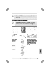
... p.2, No. 17) (SATAII_6: see p.2, No. 19) Serial ATA (SATA) Data Cable (Optional) USB 2.0 Headers (9-pin USB10_11) (see p.2 No. 25) (9-pin USB8_9) (see p.2 No. 22) English 17 ASRock H55M-GE Motherboard Please adjust the BIOS option "Clear Status" to 3.0 Gb/s data transfer rate. The current SATAII ...interface allows up to clear the record of the SATA data cable can support two USB 2.0 ports. (9-pin USB6_7) (see p.2 ...
... p.2, No. 17) (SATAII_6: see p.2, No. 19) Serial ATA (SATA) Data Cable (Optional) USB 2.0 Headers (9-pin USB10_11) (see p.2 No. 25) (9-pin USB8_9) (see p.2 No. 22) English 17 ASRock H55M-GE Motherboard Please adjust the BIOS option "Clear Status" to 3.0 Gb/s data transfer rate. The current SATAII ...interface allows up to clear the record of the SATA data cable can support two USB 2.0 ports. (9-pin USB6_7) (see p.2 ...


