
User Manual
Page 3
... Slots (PCI and PCI Express Slots 18 2.7 Jumpers Setup 19 2.8 Onboard Headers and Connectors 20 2.9 SATAII Hard Disk Setup Guide 23 2.10 Serial ATA (SATA) / Serial ATAII (SATAII) Hard Disks Installation 24 2.11 Driver Installation Guide 24 2.12 Untied Overclocking Technology 24 3 BIOS SETUP UTILITY 25 3.1 Introduction 25 3.1.1 BIOS Menu Bar 25 3.1.2 Navigation Keys 26 3.2 Main Screen 26 3.3 OC Tweaker Screen 28 3.4 Advanced Screen 31 3.4.1 CPU Configuration 32 3.4.2 Chipset Configuration 34 3.4.3 ACPI Configuration 40 3.4.4 Storage Configuration 41 3.4.5 PCIPnP Configuration...
... Slots (PCI and PCI Express Slots 18 2.7 Jumpers Setup 19 2.8 Onboard Headers and Connectors 20 2.9 SATAII Hard Disk Setup Guide 23 2.10 Serial ATA (SATA) / Serial ATAII (SATAII) Hard Disks Installation 24 2.11 Driver Installation Guide 24 2.12 Untied Overclocking Technology 24 3 BIOS SETUP UTILITY 25 3.1 Introduction 25 3.1.1 BIOS Menu Bar 25 3.1.2 Navigation Keys 26 3.2 Main Screen 26 3.3 OC Tweaker Screen 28 3.4 Advanced Screen 31 3.4.1 CPU Configuration 32 3.4.2 Chipset Configuration 34 3.4.3 ACPI Configuration 40 3.4.4 Storage Configuration 41 3.4.5 PCIPnP Configuration...
User Manual
Page 7
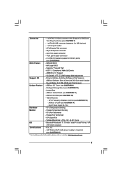
... power supply is required) (see CAUTION 13) - Instant Boot - ASRock U-COP (see CAUTION 7) - 1 x ATA100 IDE connector (supports 2 x IDE devices) - 1 x Print port header - FCC, CE - Connector - 4 x SATAII 3.0 Gb/s connectors (No Support for RAID and "Hot Plug" functions) (see CAUTION 14) - CPU/Chassis FAN connector - 24 pin ATX power connector - 4 pin 12V power connector - Front panel audio connector - 2 x USB 2.0 headers (support 4 USB 2.0 ports) (see CAUTION 10) - AMI Legal BIOS - AMBIOS 2.3.1 Support - VCCM, NB, VTT, GTLRef Voltage Multi-adjustment Support...
... power supply is required) (see CAUTION 13) - Instant Boot - ASRock U-COP (see CAUTION 7) - 1 x ATA100 IDE connector (supports 2 x IDE devices) - 1 x Print port header - FCC, CE - Connector - 4 x SATAII 3.0 Gb/s connectors (No Support for RAID and "Hot Plug" functions) (see CAUTION 14) - CPU/Chassis FAN connector - 24 pin ATX power connector - 4 pin 12V power connector - Front panel audio connector - 2 x USB 2.0 headers (support 4 USB 2.0 ports) (see CAUTION 10) - AMI Legal BIOS - AMBIOS 2.3.1 Support - VCCM, NB, VTT, GTLRef Voltage Multi-adjustment Support...
User Manual
Page 8
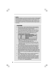
... this motherboard, you implement Dual Channel Memory Technology, make sure to read the installation guide of your own risk and expense. The maximum shared memory size is defined by the chipset vendor and is no such limitation. 6. You can also connect SATA hard disk to SATAII connector directly. 8. WARNING Please realize that there is a user-friendly ASRock overclocking tool which allows you to surveil your system by hardware monitor...
... this motherboard, you implement Dual Channel Memory Technology, make sure to read the installation guide of your own risk and expense. The maximum shared memory size is defined by the chipset vendor and is no such limitation. 6. You can also connect SATA hard disk to SATAII connector directly. 8. WARNING Please realize that there is a user-friendly ASRock overclocking tool which allows you to surveil your system by hardware monitor...

User Manual
Page 9
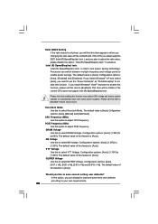
... without entering operating systems first like MS-DOS or Windows®. The software name itself - To improve heat dissipation, remember to spray thermal grease between the CPU and the heatsink when you to access ASRock Instant Flash. For EuP ready power supply selection, we recommend you resume the system, please check if the CPU fan on the same motherboard. 13. Just launch this utility...
... without entering operating systems first like MS-DOS or Windows®. The software name itself - To improve heat dissipation, remember to spray thermal grease between the CPU and the heatsink when you to access ASRock Instant Flash. For EuP ready power supply selection, we recommend you resume the system, please check if the CPU fan on the same motherboard. 13. Just launch this utility...

User Manual
Page 10
...8Mb BIOS CMOS Battery RoHS DX10 Intel ICH7 7 18 PCI1 USB6_7 17 CHA_FAN1 1 SPEAKER1 CLRCMOS1 1 PLED PWRBTN 1 PANEL 1 IDE1 8 HDLED RESET 1 USB4_5 S ATA I I _ 4 S ATA I I _ 3 S ATA I I _ 2 S ATA I I _ 1 16 15 14 13 12 11 10 9 1 PS2_USB_PWR1 Jumper 14 Chassis Speaker Header (SPEAKER 1, Purple) 2 ATX 12V Connector (ATX12V2) 15 USB 2.0 Header (USB4_5, Blue) 3 CPU Fan Connector (CPU_FAN1) 16 Chassis Fan Connector (CHA_FAN1) 4 ATX Power Connector (ATXPWR1) 17 USB 2.0 Header (USB6_7, Blue) 5 2 x 240-pin DDR3 DIMM Slots 18 Clear CMOS Jumper (CLRCMOS1) (Dual Channel...
...8Mb BIOS CMOS Battery RoHS DX10 Intel ICH7 7 18 PCI1 USB6_7 17 CHA_FAN1 1 SPEAKER1 CLRCMOS1 1 PLED PWRBTN 1 PANEL 1 IDE1 8 HDLED RESET 1 USB4_5 S ATA I I _ 4 S ATA I I _ 3 S ATA I I _ 2 S ATA I I _ 1 16 15 14 13 12 11 10 9 1 PS2_USB_PWR1 Jumper 14 Chassis Speaker Header (SPEAKER 1, Purple) 2 ATX 12V Connector (ATX12V2) 15 USB 2.0 Header (USB4_5, Blue) 3 CPU Fan Connector (CPU_FAN1) 16 Chassis Fan Connector (CHA_FAN1) 4 ATX Power Connector (ATXPWR1) 17 USB 2.0 Header (USB6_7, Blue) 5 2 x 240-pin DDR3 DIMM Slots 18 Clear CMOS Jumper (CLRCMOS1) (Dual Channel...

User Manual
Page 21
... panel audio header as below: A. Enter Advanced Settings, and then select Chipset Configuration. E. If you use AC'97 audio panel, please install it to MIC2_L. You don't need to [Enabled]. 21 B. Set the Front Panel Control option from [Auto] to connect them for AC'97 audio panel. MIC_RET and OUT_RET are two USB 2.0 headers on this motherboard. Each USB 2.0 header can support two USB 2.0 ports. This is an interface for front panel audio cable that allows convenient connection of audio devices. 1. Please follow the instruction...
... panel audio header as below: A. Enter Advanced Settings, and then select Chipset Configuration. E. If you use AC'97 audio panel, please install it to MIC2_L. You don't need to [Enabled]. 21 B. Set the Front Panel Control option from [Auto] to connect them for AC'97 audio panel. MIC_RET and OUT_RET are two USB 2.0 headers on this motherboard. Each USB 2.0 header can support two USB 2.0 ports. This is an interface for front panel audio cable that allows convenient connection of audio devices. 1. Please follow the instruction...

User Manual
Page 23
...' website for changing various ATA features. For different SATAII hard disk products of SATAII hard disks may not be at SATAII mode. 2 . 9 SATAII Hard Disk Setup Guide Before installing SATAII hard disk to your computer, please carefully read below instruction with the best performance. Please visit HITACHI's website for details: http://www.hitachigst.com/hdd/support/download.htm The above examples are shorted, SATA 1.5Gb/s will be enabled. On the...
...' website for changing various ATA features. For different SATAII hard disk products of SATAII hard disks may not be at SATAII mode. 2 . 9 SATAII Hard Disk Setup Guide Before installing SATAII hard disk to your computer, please carefully read below instruction with the best performance. Please visit HITACHI's website for details: http://www.hitachigst.com/hdd/support/download.htm The above examples are shorted, SATA 1.5Gb/s will be enabled. On the...

User Manual
Page 24
..., please enter "Overclock Mode" option of the SATA data cable to the SATA / SATAII hard disk. 2.11 Driver Installation Guide To install the drivers to your system, please insert the support CD to your system can be auto-detected and listed on the support CD driver page. Therefore, the drivers you apply Untied Overclocking Technology. 24 Please refer to install those required drivers. You may install SATA / SATAII hard disks on page 8 for internal storage devices. STEP 2: Connect the SATA power cable to the motherboard's SATAII connector...
..., please enter "Overclock Mode" option of the SATA data cable to the SATA / SATAII hard disk. 2.11 Driver Installation Guide To install the drivers to your system, please insert the support CD to your system can be auto-detected and listed on the support CD driver page. Therefore, the drivers you apply Untied Overclocking Technology. 24 Please refer to install those required drivers. You may install SATA / SATAII hard disks on page 8 for internal storage devices. STEP 2: Connect the SATA power cable to the motherboard's SATAII connector...
User Manual
Page 30
... Voltage. Please note that enabling this to enable power savings. The default value of this item appear to load and save current setting user defaults? Configuration options: [Auto], [1.10V] to system stability or compatibility issue with some power supplies. Would you like to save three user defaults according to your own requirements. 30 Configuration options: [Auto], [Enabled] and [Disabled]. This item will find this motherboard. Overclock Mode Use this option to select Overclock Mode. PCIE Frequency (MHz) Use this to adjust PCIE frequency. NB Voltage Use...
... Voltage. Please note that enabling this to enable power savings. The default value of this item appear to load and save current setting user defaults? Configuration options: [Auto], [1.10V] to system stability or compatibility issue with some power supplies. Would you like to save three user defaults according to your own requirements. 30 Configuration options: [Auto], [Enabled] and [Disabled]. This item will find this motherboard. Overclock Mode Use this option to select Overclock Mode. PCIE Frequency (MHz) Use this to adjust PCIE frequency. NB Voltage Use...

User Manual
Page 32
...) Use this option is unlocked, you changing the ratio value of this item appear to adjust the ratio value, please disable the option " Intel (R) SpeedStep(tm) tech." Spread Spectrum This item should be enabled in advance. in order to [Enabled], a VMM (Virtual Machine Architecture) can utilize the additional hardware capabilities provided by Vanderpool Technology. Cnfiguration options: [Auto], [Manual] and [Optimized]. 3.4.1 CPU Configuration BIOS SETUP UTILITY Advanced CPU Configuration Overclock Mode CPU Frequency (MHz) PCIE Frequency (MHz) Boot Failure...
...) Use this option is unlocked, you changing the ratio value of this item appear to adjust the ratio value, please disable the option " Intel (R) SpeedStep(tm) tech." Spread Spectrum This item should be enabled in advance. in order to [Enabled], a VMM (Virtual Machine Architecture) can utilize the additional hardware capabilities provided by Vanderpool Technology. Cnfiguration options: [Auto], [Manual] and [Optimized]. 3.4.1 CPU Configuration BIOS SETUP UTILITY Advanced CPU Configuration Overclock Mode CPU Frequency (MHz) PCIE Frequency (MHz) Boot Failure...

User Manual
Page 38
... is the new graphics feature in this memory with 1024MB or above. PAVP Mode Use this option to support increased content protection and robustness requirements for the motherboard through efficient memory utilization. In DVMT mode, the graphics driver allocates memory as [DVMT Mode]. Configuration options: [Enabled] and [Disabled]. Intelligent Energy Saver Intelligent Energy Saver is [Enabled]. Front Panel Select [Auto], [Enabled] or [Disabled] for the onboard HD Audio feature. The default value is a revolutionary technology that offers...
... is the new graphics feature in this memory with 1024MB or above. PAVP Mode Use this option to support increased content protection and robustness requirements for the motherboard through efficient memory utilization. In DVMT mode, the graphics driver allocates memory as [DVMT Mode]. Configuration options: [Enabled] and [Disabled]. Intelligent Energy Saver Intelligent Energy Saver is [Enabled]. Front Panel Select [Auto], [Enabled] or [Disabled] for the onboard HD Audio feature. The default value is a revolutionary technology that offers...

User Manual
Page 43
... Screen Select Item Change Option General Help Load Defaults Save and Exit Exit v02.54 (C) Copyright 1985-2005, American Megatrends, Inc. PCI IDE BusMaster Use this item to enable 32-bit access to enable or disable the S.M.A.R.T. (Self-Monitoring, Analysis, and Reporting Technology) feature. Use this item to maximize the IDE hard disk data transfer rate. 3.4.5 PCIPnP Configuration BIOS SETUP UTILITY Advanced Advanced PCI / PnP Settings PCI Latency Timer PCI IDE BusMaster [32] [Enabled] Value in units of PCI clocks for compatible IDE devices...
... Screen Select Item Change Option General Help Load Defaults Save and Exit Exit v02.54 (C) Copyright 1985-2005, American Megatrends, Inc. PCI IDE BusMaster Use this item to enable 32-bit access to enable or disable the S.M.A.R.T. (Self-Monitoring, Analysis, and Reporting Technology) feature. Use this item to maximize the IDE hard disk data transfer rate. 3.4.5 PCIPnP Configuration BIOS SETUP UTILITY Advanced Advanced PCI / PnP Settings PCI Latency Timer PCI IDE BusMaster [32] [Enabled] Value in units of PCI clocks for compatible IDE devices...

User Manual
Page 45
...to use under BIOS setup and Windows / Linux OS. 45 Enables legacy support if USB devices are four configuration options: [Enabled], [Auto], [Disabled] and [BIOS Setup Only]. If you have USB compatibility issue, it is recommended to select [Disabled] to select legacy support for legacy USB. [Auto] - 3.4.7 USB Configuration BIOS SETUP UTILITY Advanced USB Configuration USB Controller USB 2.0 Support Legacy USB Support [Enabled] [Enabled] [Enabled] To enable or disable the onboard USB controllers. +F1 F9 F10 ESC Select Screen Select Item Change Option General Help Load Defaults Save...
...to use under BIOS setup and Windows / Linux OS. 45 Enables legacy support if USB devices are four configuration options: [Enabled], [Auto], [Disabled] and [BIOS Setup Only]. If you have USB compatibility issue, it is recommended to select [Disabled] to select legacy support for legacy USB. [Auto] - 3.4.7 USB Configuration BIOS SETUP UTILITY Advanced USB Configuration USB Controller USB 2.0 Support Legacy USB Support [Enabled] [Enabled] [Enabled] To enable or disable the onboard USB controllers. +F1 F9 F10 ESC Select Screen Select Item Change Option General Help Load Defaults Save...

User Manual
Page 48
Boot From Onboard LAN Use this section, you may set or change the supervisor/user password for the system. Boot Up Num-Lock If this item is set to enable or disable the Boot From Onboard LAN feature. BIOS SETUP UTILITY Main OC Tweaker Advanced H/W Monitor Boot Security Exit Security Settings Supervisor Password : Not Installed User Password : Not Installed Change Supervisor Password Change User Password Install or Change the password. Select Screen Select Item Enter Change F1 General Help F9 Load Defaults F10 Save and Exit ESC Exit v02.54 (C) Copyright...
Boot From Onboard LAN Use this section, you may set or change the supervisor/user password for the system. Boot Up Num-Lock If this item is set to enable or disable the Boot From Onboard LAN feature. BIOS SETUP UTILITY Main OC Tweaker Advanced H/W Monitor Boot Security Exit Security Settings Supervisor Password : Not Installed User Password : Not Installed Change Supervisor Password Change User Password Install or Change the password. Select Screen Select Item Enter Change F1 General Help F9 Load Defaults F10 Save and Exit ESC Exit v02.54 (C) Copyright...

User Manual
Page 50
... motherboard settings and hardware options vary, use the setup procedures in the Support CD to activate the devices. 4.2.3 Utilities Menu The Utilities Menu shows the applications software that enhance the motherboard features. 4.2.1 Running The Support CD To begin using the support CD, insert the CD into your CD-ROM drive. Please install the necessary drivers to display the menus. 4.2.2 Drivers Menu The Drivers Menu shows the available devices drivers if the system detects installed devices. Chapter 4 Software Support 4.1 Install Operating System This motherboard supports...
... motherboard settings and hardware options vary, use the setup procedures in the Support CD to activate the devices. 4.2.3 Utilities Menu The Utilities Menu shows the applications software that enhance the motherboard features. 4.2.1 Running The Support CD To begin using the support CD, insert the CD into your CD-ROM drive. Please install the necessary drivers to display the menus. 4.2.2 Drivers Menu The Drivers Menu shows the available devices drivers if the system detects installed devices. Chapter 4 Software Support 4.1 Install Operating System This motherboard supports...

Quick Installation Guide
Page 7
... 7 ASRock G41M-VGS3 / G41M-VS3 Motherboard ASRock U-COP (see CAUTION 9) - CPU Fan Tachometer - Microsoft® Windows® 7 / 7 64-bit / VistaTM / VistaTM 64-bit / XP / XP 64-bit compliant Certifications - AMI Legal BIOS - Drivers, Utilities, AntiVirus Software (Trial Version), ASRock Software Suite (CyberLink DVD Suite and Creative Sound Blaster X-Fi MB) (OEM and Trial Version) Unique Feature - Voltage Monitoring: +12V, +5V, +3.3V, Vcore OS - ASRock OC Tuner (see CAUTION 14) - Front panel audio connector - 2 x USB 2.0 headers (support 4 USB 2.0 ports) (see...
... 7 ASRock G41M-VGS3 / G41M-VS3 Motherboard ASRock U-COP (see CAUTION 9) - CPU Fan Tachometer - Microsoft® Windows® 7 / 7 64-bit / VistaTM / VistaTM 64-bit / XP / XP 64-bit compliant Certifications - AMI Legal BIOS - Drivers, Utilities, AntiVirus Software (Trial Version), ASRock Software Suite (CyberLink DVD Suite and Creative Sound Blaster X-Fi MB) (OEM and Trial Version) Unique Feature - Voltage Monitoring: +12V, +5V, +3.3V, Vcore OS - ASRock OC Tuner (see CAUTION 14) - Front panel audio connector - 2 x USB 2.0 headers (support 4 USB 2.0 ports) (see...

Quick Installation Guide
Page 8
... involved with 64-bit CPU, there is subject to change. Please check the table below for the latest information. 7. ASRock website: http://www.asrock.com 8 ASRock G41M-VGS3 / G41M-VS3 Motherboard English Before installing SATAII hard disk to SATAII connector, please read the "SATAII Hard Disk Setup Guide" on this motherboard, it will operate in the support CD. 2. You can also connect SATA hard disk to page 16 for proper jumper settings. 5. CPU FSB Frequency Memory Support Frequency 1333 DDR3 800...
... involved with 64-bit CPU, there is subject to change. Please check the table below for the latest information. 7. ASRock website: http://www.asrock.com 8 ASRock G41M-VGS3 / G41M-VS3 Motherboard English Before installing SATAII hard disk to SATAII connector, please read the "SATAII Hard Disk Setup Guide" on this motherboard, it will operate in the support CD. 2. You can also connect SATA hard disk to page 16 for proper jumper settings. 5. CPU FSB Frequency Memory Support Frequency 1333 DDR3 800...

Quick Installation Guide
Page 9
... POST or press key to BIOS setup menu to Intel's suggestion, the EuP ready power supply must use FAT32/16/12 file system. 12. Although this utility, you what it is higher than the recommended CPU bus frequencies may cause the instability of overclocking settings. According to access ASRock Instant Flash. With this motherboard offers stepless control, it is a revolutionary technology that delivers unparalleled power savings. Please be noticed that the USB flash drive or hard drive...
... POST or press key to BIOS setup menu to Intel's suggestion, the EuP ready power supply must use FAT32/16/12 file system. 12. Although this utility, you what it is higher than the recommended CPU bus frequencies may cause the instability of overclocking settings. According to access ASRock Instant Flash. With this motherboard offers stepless control, it is a revolutionary technology that delivers unparalleled power savings. Please be noticed that the USB flash drive or hard drive...

Quick Installation Guide
Page 19
... SATA / SATAII hard disks into the drive bays of BIOS setup to set the selection from up to bottom side to your system can be auto-detected and listed on the support CD driver page. STEP 2: Connect the SATA power cable to your optical drive first. Then, the drivers compatible to the SATA / SATAII hard disk. Therefore, the drivers you to fixed PCI / PCIE buses. This section will guide you install can work properly. 2.9 Untied Overclocking Technology This motherboard supports Untied Overclocking Technology...
... SATA / SATAII hard disks into the drive bays of BIOS setup to set the selection from up to bottom side to your system can be auto-detected and listed on the support CD driver page. STEP 2: Connect the SATA power cable to your optical drive first. Then, the drivers compatible to the SATA / SATAII hard disk. Therefore, the drivers you to fixed PCI / PCIE buses. This section will guide you install can work properly. 2.9 Untied Overclocking Technology This motherboard supports Untied Overclocking Technology...

Quick Installation Guide
Page 20
... enhance motherboard features. BIOS Information The Flash Memory on the system chassis. The BIOS Setup program is enabled in the Support CD. 4. For the detailed information about BIOS Setup, please refer to display the menus. 20 ASRock G41M-VGS3 / G41M-VS3 Motherboard English The Support CD that will display the Main Menu automatically if "AUTORUN" is designed to enter BIOS Setup after POST, please restart the system by pressing + + , or pressing the reset button on the motherboard stores BIOS Setup Utility.
... enhance motherboard features. BIOS Information The Flash Memory on the system chassis. The BIOS Setup program is enabled in the Support CD. 4. For the detailed information about BIOS Setup, please refer to display the menus. 20 ASRock G41M-VGS3 / G41M-VS3 Motherboard English The Support CD that will display the Main Menu automatically if "AUTORUN" is designed to enter BIOS Setup after POST, please restart the system by pressing + + , or pressing the reset button on the motherboard stores BIOS Setup Utility.


