
User Manual
Page 2
... fitness for a particular purpose. "Perchlorate Material-special handling may apply, see www.dtsc.ca.gov/hazardouswaste/perchlorate" ASRock Website: http://www.asrock.com 2 Copyright Notice: No part of this manual may be reproduced, transcribed, transmitted, or translated in any language... on this manual. ASRock assumes no event shall ASRock, its directors, officers, employees, or agents be constructed as a commitment by ASRock. This device complies with Part 15 of the FCC Rules. Disclaimer: Specifications and information contained in this motherboard contains Perchlorate, a toxic...
... fitness for a particular purpose. "Perchlorate Material-special handling may apply, see www.dtsc.ca.gov/hazardouswaste/perchlorate" ASRock Website: http://www.asrock.com 2 Copyright Notice: No part of this manual may be reproduced, transcribed, transmitted, or translated in any language... on this manual. ASRock assumes no event shall ASRock, its directors, officers, employees, or agents be constructed as a commitment by ASRock. This device complies with Part 15 of the FCC Rules. Disclaimer: Specifications and information contained in this motherboard contains Perchlorate, a toxic...
User Manual
Page 3
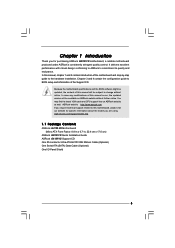
Contents 1 Introduction 5 1.1 Package Contents 5 1.2 Specifications 6 1.3 Motherboard Layout 10 1.4 I/O Panel 11 2 Installation 12 2.1 Screw Holes 12 2.2 Pre-installation Precautions 12 2.3 CPU Installation 13 2.4 Installation of Heatsink and CPU fan 15 2.5 Installation of ...
Contents 1 Introduction 5 1.1 Package Contents 5 1.2 Specifications 6 1.3 Motherboard Layout 10 1.4 I/O Panel 11 2 Installation 12 2.1 Screw Holes 12 2.2 Pre-installation Precautions 12 2.3 CPU Installation 13 2.4 Installation of Heatsink and CPU fan 15 2.5 Installation of ...
User Manual
Page 5
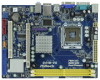
... model you for purchasing ASRock G41M-VS motherboard, a reliable motherboard produced under ASRock's consistently stringent quality control. You may find the latest VGA cards and CPU support lists on ASRock website without notice. www.asrock.com/support/index.asp 1.1 Package Contents ASRock G41M-VS Motherboard (Micro ATX Form Factor: 8.8-in x 6.7-in, 22.4 cm x 17.0 cm) ASRock G41M-VS Quick Installation Guide ASRock G41M-VS Support CD One 80...
... model you for purchasing ASRock G41M-VS motherboard, a reliable motherboard produced under ASRock's consistently stringent quality control. You may find the latest VGA cards and CPU support lists on ASRock website without notice. www.asrock.com/support/index.asp 1.1 Package Contents ASRock G41M-VS Motherboard (Micro ATX Form Factor: 8.8-in x 6.7-in, 22.4 cm x 17.0 cm) ASRock G41M-VS Quick Installation Guide ASRock G41M-VS Support CD One 80...

User Manual
Page 8
...under Windows® XP and Windows® VistaTM. Overclocking may be done at your hardware devices to adjust your system. This motherboard supports Dual Channel Memory Technology. For Windows® XP 64-bit and Windows® VistaTM 64bit with overclocking, including adjusting ... Windows® VistaTM 64-bit / VistaTM / XP 64-bit / XP SP1 or SP2 / 2000 SP4. 9. ASRock website: http://www.asrock.com 10. CAUTION! 1. This motherboard supports Untied Overclocking Technology. Please read the installation guide of Intelligent Energy Saver. Before you to SATAII mode. Featuring an...
...under Windows® XP and Windows® VistaTM. Overclocking may be done at your hardware devices to adjust your system. This motherboard supports Dual Channel Memory Technology. For Windows® XP 64-bit and Windows® VistaTM 64bit with overclocking, including adjusting ... Windows® VistaTM 64-bit / VistaTM / XP 64-bit / XP SP1 or SP2 / 2000 SP4. 9. ASRock website: http://www.asrock.com 10. CAUTION! 1. This motherboard supports Untied Overclocking Technology. Please read the installation guide of Intelligent Energy Saver. Before you to SATAII mode. Featuring an...

User Manual
Page 9
.... Please be noted that the USB flash drive or hard drive must meet EuP standard, an EuP ready motherboard and an EuP ready power supply are required. To improve heat dissipation, remember to spray thermal grease between ...flash utility. Just launch this utility, you resume the system, please check if the CPU fan on the motherboard functions properly and unplug the power cord, then plug it is higher than the recommended CPU bus frequencies may.... With this tool and save the new BIOS file to access ASRock Instant Flash. Although this motherboard offers stepless control, it back again.
.... Please be noted that the USB flash drive or hard drive must meet EuP standard, an EuP ready motherboard and an EuP ready power supply are required. To improve heat dissipation, remember to spray thermal grease between ...flash utility. Just launch this utility, you resume the system, please check if the CPU fan on the motherboard functions properly and unplug the power cord, then plug it is higher than the recommended CPU bus frequencies may.... With this tool and save the new BIOS file to access ASRock Instant Flash. Although this motherboard offers stepless control, it back again.
User Manual
Page 10
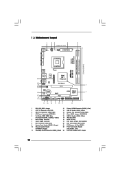
1.3 Motherboard Layout 1 23 4 5 17.0cm (6.7 in) PS2 Mouse PS2 Keyboard 1 PS2_USB_PWR1 ATX12V2 CPU_FAN1 COM1 22.4cm (8.8 in) DDRII_1 (64 bit, 240-piFnSmBod8ul0e)0 DDRII_2 (64 bit, 240-piFnSmBod8ul0e)0 FSB1333 DDR2 800 Dual Channel VGA1 G41M-VS USB 2.0 T: USB2 B: USB3 1 Top: Line In Center: Line Out Bottom: Mic In 23 USB 2.0 T: USB0 B: USB1 Top: RJ-45...
1.3 Motherboard Layout 1 23 4 5 17.0cm (6.7 in) PS2 Mouse PS2 Keyboard 1 PS2_USB_PWR1 ATX12V2 CPU_FAN1 COM1 22.4cm (8.8 in) DDRII_1 (64 bit, 240-piFnSmBod8ul0e)0 DDRII_2 (64 bit, 240-piFnSmBod8ul0e)0 FSB1333 DDR2 800 Dual Channel VGA1 G41M-VS USB 2.0 T: USB2 B: USB3 1 Top: Line In Center: Line Out Bottom: Mic In 23 USB 2.0 T: USB0 B: USB1 Top: RJ-45...

User Manual
Page 12
... touch a safety grounded object before you uninstall any component. 2. Make sure to motherboard components. 2.1 Screw Holes Place screws into it on the carpet or the like. Chapter 2 Installation G41M-VS is detached from the wall socket before installing or removing the motherboard. Before you and damages to unplug the power cord before touching any...
... touch a safety grounded object before you uninstall any component. 2. Make sure to motherboard components. 2.1 Screw Holes Place screws into it on the carpet or the like. Chapter 2 Installation G41M-VS is detached from the wall socket before installing or removing the motherboard. Before you and damages to unplug the power cord before touching any...

User Manual
Page 14
... orientation key notches of the CPU with load plate tab under retention tab of load lever. 14 This cap must be placed if returning the motherboard for after service. Step 3. Remove PnP Cap (Pick and Place Cap): Use your left hand index finger and thumb to support the load plate edge...
... orientation key notches of the CPU with load plate tab under retention tab of load lever. 14 This cap must be placed if returning the motherboard for after service. Step 3. Remove PnP Cap (Pick and Place Cap): Use your left hand index finger and thumb to support the load plate edge...

User Manual
Page 15
... dissipation. Step 4. Rotate the fastener clockwise, then press down the fasteners without rotating them clockwise, the heatsink cannot be secured on the motherboard (CPU_FAN1, see page 10, No. 3). Below is equipped with 775-Pin socket that the CPU and the heatsink are oriented on side... closest to the CPU fan connector on the motherboard. Place the heatsink onto the socket. Apply thermal interface material onto center of IHS on fastener caps with thumb to dissipate heat. Step ...
... dissipation. Step 4. Rotate the fastener clockwise, then press down the fasteners without rotating them clockwise, the heatsink cannot be secured on the motherboard (CPU_FAN1, see page 10, No. 3). Below is equipped with 775-Pin socket that the CPU and the heatsink are oriented on side... closest to the CPU fan connector on the motherboard. Place the heatsink onto the socket. Apply thermal interface material onto center of IHS on fastener caps with thumb to dissipate heat. Step ...

User Manual
Page 16
...notch break notch break The DIMM only fits in one memory module or two non-identical memory modules, it will cause permanent damage to the motherboard and the DIMM if you always need to install two identical (the same brand, speed, size and chip-type) memory modules in place ... 1. Align a DIMM on the slot such that the notch on the DIMM matches the break on the slot. 2.5 Installation of Memory Modules (DIMM) G41M-VS motherboard provides two 240-pin DDR2 (Double Data Rate 2) DIMM slots, and supports Dual Channel Memory Technology. Installing a DIMM Please make sure to activate the Dual...
...notch break notch break The DIMM only fits in one memory module or two non-identical memory modules, it will cause permanent damage to the motherboard and the DIMM if you always need to install two identical (the same brand, speed, size and chip-type) memory modules in place ... 1. Align a DIMM on the slot such that the notch on the DIMM matches the break on the slot. 2.5 Installation of Memory Modules (DIMM) G41M-VS motherboard provides two 240-pin DDR2 (Double Data Rate 2) DIMM slots, and supports Dual Channel Memory Technology. Installing a DIMM Please make sure to activate the Dual...

User Manual
Page 17
... (PCIE x16 slot) is used to install expansion card that the power supply is switched off or the power cord is completely seated on this motherboard. Step 4. Installing an expansion card Step 1. Step 2. Keep the screws for PCI Express card with the slot and press firmly until the card is unplugged...
... (PCIE x16 slot) is used to install expansion card that the power supply is switched off or the power cord is completely seated on this motherboard. Step 4. Installing an expansion card Step 1. Step 2. Keep the screws for PCI Express card with the slot and press firmly until the card is unplugged...

User Manual
Page 18
...cap is placed on CLRCMOS1 for 15 seconds, use a jumper cap to Disk), and S5 (Soft Off) will be disabled. With an ASRock EuP ready motherboard and a power supply that when EUP_LAN jumper is able to submit EuP standard. EUP_LAN1 EUP_AUDIO1 (Disable EuP) 18 2.7 Jumpers Setup The illustration... EUP_AUDIO jumper design decreases the power consumption of this power saving function, you to meet EuP standard. If you want to disable this motherboard to clear the data in CMOS includes system setup information such as system password, date, time, and system setup parameters. Please be ...
...cap is placed on CLRCMOS1 for 15 seconds, use a jumper cap to Disk), and S5 (Soft Off) will be disabled. With an ASRock EuP ready motherboard and a power supply that when EUP_LAN jumper is able to submit EuP standard. EUP_LAN1 EUP_AUDIO1 (Disable EuP) 18 2.7 Jumpers Setup The illustration... EUP_AUDIO jumper design decreases the power consumption of this power saving function, you to meet EuP standard. If you want to disable this motherboard to clear the data in CMOS includes system setup information such as system password, date, time, and system setup parameters. Please be ...

User Manual
Page 19
... for the details. Serial ATA (SATA) Data Cable (Optional) Either end of the SATA data cable can be connected to the instruction of the motherboard! Do NOT place jumper caps over the headers and connectors will cause permanent damage of your IDE device vendor for internal storage devices. Serial ATAII... Connectors (SATAII_1: see p.10, No. 12) (SATAII_2: see p.10 No. 8) PIN1 IDE1 connect the blue end connect the black end to the motherboard to the IDE devices 80-conductor ATA 66/100 cable Note: Please refer to the SATA / SATAII hard disk or the SATAII connector on the...
... for the details. Serial ATA (SATA) Data Cable (Optional) Either end of the SATA data cable can be connected to the instruction of the motherboard! Do NOT place jumper caps over the headers and connectors will cause permanent damage of your IDE device vendor for internal storage devices. Serial ATAII... Connectors (SATAII_1: see p.10, No. 12) (SATAII_2: see p.10 No. 8) PIN1 IDE1 connect the blue end connect the black end to the motherboard to the IDE devices 80-conductor ATA 66/100 cable Note: Please refer to the SATA / SATAII hard disk or the SATAII connector on the...

User Manual
Page 20
...) to OUT2_R and Audio_L (LIN) to the front panel audio header as below: A. Enter Windows system. D. MIC_RET and OUT_RET are two USB 2.0 headers on this motherboard. Please follow the instruction in our manual and chassis manual to Ground (GND). B. USB 2.0 Headers (9-pin USB6_7) (see p.10 No. 16) (9-pin USB4_5) (see p.10...
...) to OUT2_R and Audio_L (LIN) to the front panel audio header as below: A. Enter Windows system. D. MIC_RET and OUT_RET are two USB 2.0 headers on this motherboard. Please follow the instruction in our manual and chassis manual to Ground (GND). B. USB 2.0 Headers (9-pin USB6_7) (see p.10 No. 16) (9-pin USB4_5) (see p.10...

User Manual
Page 21
... +5V This header accommodates several system front panel functions. If you plan to connect the 3-Pin CPU fan to the CPU fan connector on this motherboard, please connect it to the ground pin. System Panel Header (9-pin PANEL1) (see p.10 No. 9) Chassis Speaker Header (4-pin SPEAKER 1) (see p.10 ...Windows® VistaTM / VistaTM 64-bit OS: Go to make the Front Mic as default record device. Please connect the chassis speaker to this motherboard provides 4-Pin CPU fan (Quiet Fan) support, the 3-Pin CPU fan still can work successfully even without the fan speed control function. For...
... +5V This header accommodates several system front panel functions. If you plan to connect the 3-Pin CPU fan to the CPU fan connector on this motherboard, please connect it to the ground pin. System Panel Header (9-pin PANEL1) (see p.10 No. 9) Chassis Speaker Header (4-pin SPEAKER 1) (see p.10 ...Windows® VistaTM / VistaTM 64-bit OS: Go to make the Front Mic as default record device. Please connect the chassis speaker to this motherboard provides 4-Pin CPU fan (Quiet Fan) support, the 3-Pin CPU fan still can work successfully even without the fan speed control function. For...

User Manual
Page 22
... Power Connector 24 (24-pin ATXPWR1) (see p.10 No. 2) Please note that it is necessary to connect a power supply with ATX 12V plug to this motherboard provides 24-pin ATX power connector, it can still work if you adopt a traditional 20-pin ATX power supply. To use the 20-pin ATX...
... Power Connector 24 (24-pin ATXPWR1) (see p.10 No. 2) Please note that it is necessary to connect a power supply with ATX 12V plug to this motherboard provides 24-pin ATX power connector, it can still work if you adopt a traditional 20-pin ATX power supply. To use the 20-pin ATX...
User Manual
Page 24
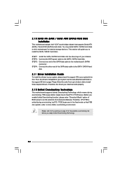
... end of BIOS setup to set the selection from up to bottom side to the motherboard's SATAII connector. Before you install can work properly. 2 . 1 2 Untied Overclocking Technology This motherboard supports Untied Overclocking Technology, which means during overclocking, but PCI / PCIE buses are ...SATA data cable to install those required drivers. 2 . 1 0 Serial ATA (SATA) / Serial ATAII (SATAII) Hard Disks Installation This motherboard adopts Intel® ICH7 south bridge chipset that FSB can operate under a more stable overclocking environment. You may install SATA / SATAII hard disks...
... end of BIOS setup to set the selection from up to bottom side to the motherboard's SATAII connector. Before you install can work properly. 2 . 1 2 Untied Overclocking Technology This motherboard supports Untied Overclocking Technology, which means during overclocking, but PCI / PCIE buses are ...SATA data cable to install those required drivers. 2 . 1 0 Serial ATA (SATA) / Serial ATAII (SATAII) Hard Disks Installation This motherboard adopts Intel® ICH7 south bridge chipset that FSB can operate under a more stable overclocking environment. You may install SATA / SATAII hard disks...

User Manual
Page 25
... and descriptions are for reference purpose only, and they may run the BIOS SETUP UTILITY when you wish to choose among the selections on the motherboard stores the BIOS SETUP UTILITY. Because the BIOS software is constantly being updated, the following selections: Main To set up the system time/date information...
... and descriptions are for reference purpose only, and they may run the BIOS SETUP UTILITY when you wish to choose among the selections on the motherboard stores the BIOS SETUP UTILITY. Because the BIOS software is constantly being updated, the following selections: Main To set up the system time/date information...

User Manual
Page 27
... operating frequency: [333MHz (DDR2 667)] and [400MHz (DDR2 800)]. 27 DRAM Frequency If [Auto] is selected, the motherboard will detect the memory module(s) inserted and assigns appropriate frequency automatically. CPU Frequency (MHz) Use this motherboard. BIOS SETUP UTILITY Main OC Tweaker Advanced H/W Monitor Boot Security Exit OC Tweaker Settings Overclock Mode CPU...
... operating frequency: [333MHz (DDR2 667)] and [400MHz (DDR2 800)]. 27 DRAM Frequency If [Auto] is selected, the motherboard will detect the memory module(s) inserted and assigns appropriate frequency automatically. CPU Frequency (MHz) Use this motherboard. BIOS SETUP UTILITY Main OC Tweaker Advanced H/W Monitor Boot Security Exit OC Tweaker Settings Overclock Mode CPU...
User Manual
Page 38
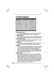
... with other system components. Configuration options: [Enabled] and [Disabled]. PAVP is cooperatively using this option to support increased content protection and robustness requirements for the motherboard through efficient memory utilization. In DVMT mode, the graphics driver allocates memory as the boot graphic adapter priority.
... with other system components. Configuration options: [Enabled] and [Disabled]. PAVP is cooperatively using this option to support increased content protection and robustness requirements for the motherboard through efficient memory utilization. In DVMT mode, the graphics driver allocates memory as the boot graphic adapter priority.

