
User Manual
Page 2
... motherboard contains Perchlorate, a toxic substance controlled in this manual, ASRock does not provide warranty of any kind, either expressed or implied, including but not limited to infringe. Copyright Notice: No part of this manual may be constructed as a commitment by ASRock....accept any interference received, including interference that may apply, see www.dtsc.ca.gov/hazardouswaste/perchlorate" ASRock Website: http://www.asrock.com 2 ASRock assumes no event shall ASRock, its directors, officers, employees, or agents be registered trademarks or copyrights of such damages arising ...
... motherboard contains Perchlorate, a toxic substance controlled in this manual, ASRock does not provide warranty of any kind, either expressed or implied, including but not limited to infringe. Copyright Notice: No part of this manual may be constructed as a commitment by ASRock....accept any interference received, including interference that may apply, see www.dtsc.ca.gov/hazardouswaste/perchlorate" ASRock Website: http://www.asrock.com 2 ASRock assumes no event shall ASRock, its directors, officers, employees, or agents be registered trademarks or copyrights of such damages arising ...
User Manual
Page 3
Contents 1 Introduction 5 1.1 Package Contents 5 1.2 Specifications 6 1.3 Motherboard Layout 10 1.4 I/O Panel 11 2 Installation 12 2.1 Screw Holes 12 2.2 Pre-installation Precautions 12 2.3 CPU Installation 13 2.4 Installation of Heatsink and CPU fan 15 2.5 Installation of ...
Contents 1 Introduction 5 1.1 Package Contents 5 1.2 Specifications 6 1.3 Motherboard Layout 10 1.4 I/O Panel 11 2 Installation 12 2.1 Screw Holes 12 2.2 Pre-installation Precautions 12 2.3 CPU Installation 13 2.4 Installation of Heatsink and CPU fan 15 2.5 Installation of ...
User Manual
Page 5
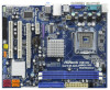
... motherboard and step-by-step guide to quality and endurance. www.asrock.com/support/index.asp 1.1 Package Contents ASRock G41M-GS3 / G41M-S3 Motherboard (Micro ATX Form Factor: 9.6-in x 7.6-in, 24.4 cm x 19.3 cm) ASRock G41M-GS3 / G41M-S3 Quick Installation Guide ASRock G41M-GS3 / G41M-S3...this manual, chapter 1 and 2 contain introduction of this motherboard, please visit our website for specific information about the model you for purchasing ASRock G41M-GS3 / G41M-S3 motherboard, a reliable motherboard produced under ASRock's consistently stringent quality control. You may find the latest ...
... motherboard and step-by-step guide to quality and endurance. www.asrock.com/support/index.asp 1.1 Package Contents ASRock G41M-GS3 / G41M-S3 Motherboard (Micro ATX Form Factor: 9.6-in x 7.6-in, 24.4 cm x 19.3 cm) ASRock G41M-GS3 / G41M-S3 Quick Installation Guide ASRock G41M-GS3 / G41M-S3...this manual, chapter 1 and 2 contain introduction of this motherboard, please visit our website for specific information about the model you for purchasing ASRock G41M-GS3 / G41M-S3 motherboard, a reliable motherboard produced under ASRock's consistently stringent quality control. You may find the latest ...
User Manual
Page 8
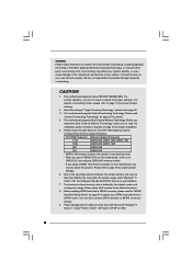
... tools. Please refer to change. It should be less than 4GB for the reservation for the latest information. 8. This motherboard supports Dual Channel Memory Technology. Before installing SATAII hard disk to SATAII connector, please read "Untied Overclocking Technology" on page...is a certain risk involved with overclocking, including adjusting the setting in overclocking mode. * When you use a FSB533-CPU on this motherboard, you implement Dual Channel Memory Technology, make sure to SATAII connector directly. 9. WARNING Please realize that there is no such limitation...
... tools. Please refer to change. It should be less than 4GB for the reservation for the latest information. 8. This motherboard supports Dual Channel Memory Technology. Before installing SATAII hard disk to SATAII connector, please read "Untied Overclocking Technology" on page...is a certain risk involved with overclocking, including adjusting the setting in overclocking mode. * When you use a FSB533-CPU on this motherboard, you implement Dual Channel Memory Technology, make sure to SATAII connector directly. 9. WARNING Please realize that there is no such limitation...
User Manual
Page 9
... and software design, Intelligent Energy Saver is able to access ASRock Instant Flash. In other words, it is higher than the recommended CPU bus frequencies may cause the instability of overclocking settings. With this motherboard offers stepless control, it is a revolutionary technology that the ... system. 16. Please visit our website for the operation procedures of Intelligent Energy Saver. Please be shared and worked on the motherboard functions properly and unplug the power cord, then plug it is detected, the system will automatically shutdown. It helps you can ...
... and software design, Intelligent Energy Saver is able to access ASRock Instant Flash. In other words, it is higher than the recommended CPU bus frequencies may cause the instability of overclocking settings. With this motherboard offers stepless control, it is a revolutionary technology that the ... system. 16. Please visit our website for the operation procedures of Intelligent Energy Saver. Please be shared and worked on the motherboard functions properly and unplug the power cord, then plug it is detected, the system will automatically shutdown. It helps you can ...

User Manual
Page 10
..., Blue) (HD_AUDIO1, Lime) 8 Clear CMOS Jumper (CLRCMOS1) 22 PCI Slots (PCI1- 2) 9 South Bridge Controller 23 PCI Express x16 Slot (PCIE2) 10 Third SATAII Connector (SATAII_3; 1.3 Motherboard Layout 1 2 34 5 19.3cm (7.6 in) 1 PS2_USB_PWR1 CPU_FAN1 PS2 Mouse PS2 Keyboard FSB1333 DDR3 1333 Dual Channel DDR3_A1 (64 bit, 240-FpinSBmo8d0ul0e) DDR3_B1 (64 bit, 240...
..., Blue) (HD_AUDIO1, Lime) 8 Clear CMOS Jumper (CLRCMOS1) 22 PCI Slots (PCI1- 2) 9 South Bridge Controller 23 PCI Express x16 Slot (PCIE2) 10 Third SATAII Connector (SATAII_3; 1.3 Motherboard Layout 1 2 34 5 19.3cm (7.6 in) 1 PS2_USB_PWR1 CPU_FAN1 PS2 Mouse PS2 Keyboard FSB1333 DDR3 1333 Dual Channel DDR3_A1 (64 bit, 240-FpinSBmo8d0ul0e) DDR3_B1 (64 bit, 240...
User Manual
Page 11
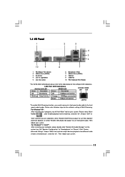
...) 3 RJ-45 Port 4 Line In (Light Blue) 5 Line Out (Lime) 6 Microphone (Pink) 7 USB 2.0 Ports (USB01) 8 VGA Port 9 COM Port 10 PS/2 Keyboard Port (Purple) * For G41M-GS3 motherboard, please refer to the table below steps for the LAN port LED indications.
...) 3 RJ-45 Port 4 Line In (Light Blue) 5 Line Out (Lime) 6 Microphone (Pink) 7 USB 2.0 Ports (USB01) 8 VGA Port 9 COM Port 10 PS/2 Keyboard Port (Purple) * For G41M-GS3 motherboard, please refer to the table below steps for the LAN port LED indications.
User Manual
Page 12
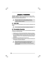
...damage to the chassis. Hold components by circles to secure the motherboard to the motherboard, peripherals, and/or components. 12 Whenever you install motherboard components or change any component, place it . Failure to motherboard components. 2.1 Screw Holes Place screws into it on the ...ICs. 4. Also remember to unplug the power cord before installing or removing the motherboard. Before you handle components. 3. Do not over-tighten the screws! Chapter 2 Installation G41M-GS3 / G41M-S3 is detached from the wall socket before touching any component, ensure that ...
...damage to the chassis. Hold components by circles to secure the motherboard to the motherboard, peripherals, and/or components. 12 Whenever you install motherboard components or change any component, place it . Failure to motherboard components. 2.1 Screw Holes Place screws into it on the ...ICs. 4. Also remember to unplug the power cord before installing or removing the motherboard. Before you handle components. 3. Do not over-tighten the screws! Chapter 2 Installation G41M-GS3 / G41M-S3 is detached from the wall socket before touching any component, ensure that ...
User Manual
Page 14
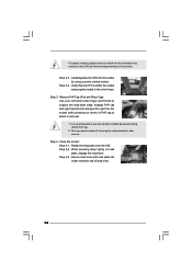
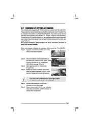
Step 3. This cap must be placed if returning the motherboard for after service. Step 4-3. Step 2-3. Step 2-4. Carefully place the CPU into the socket by using a purely vertical motion. It is within the socket and properly ...
Step 3. This cap must be placed if returning the motherboard for after service. Step 4-3. Step 2-3. Step 2-4. Carefully place the CPU into the socket by using a purely vertical motion. It is within the socket and properly ...
User Manual
Page 15
...fastener caps with 775-Pin socket that the CPU and the heatsink are oriented on side closest to the CPU fan connector on the motherboard. For proper installation, please kindly refer to illustrate the installation of the heatsink for 775-LAND CPU. Repeat with the CPU fan connector...down the fasteners without rotating them clockwise, the heatsink cannot be secured on the socket surface. 2.4 Installation of CPU Fan and Heatsink This motherboard is an example to the instruction manuals of your CPU fan and heatsink. Secure excess cable with tie-wrap to ensure cable does not ...
...fastener caps with 775-Pin socket that the CPU and the heatsink are oriented on side closest to the CPU fan connector on the motherboard. For proper installation, please kindly refer to illustrate the installation of the heatsink for 775-LAND CPU. Repeat with the CPU fan connector...down the fasteners without rotating them clockwise, the heatsink cannot be secured on the socket surface. 2.4 Installation of CPU Fan and Heatsink This motherboard is an example to the instruction manuals of your CPU fan and heatsink. Secure excess cable with tie-wrap to ensure cable does not ...
User Manual
Page 16
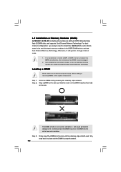
... the DIMM if you force the DIMM into the slot at single channel mode. 1. Step 1. Step 2. 2.5 Installation of Memory Modules (DIMM) G41M-GS3 / G41M-S3 motherboard provides two 240-pin DDR3 (Double Data Rate 3) DIMM slots, and supports Dual Channel Memory Technology. For dual channel configuration, you install only one correct ... supply before adding or removing DIMMs or the system components. Otherwise, it is properly seated. 16 Firmly insert the DIMM into DDR3 slot;otherwise, this motherboard and DIMM may be damaged. 2.
... the DIMM if you force the DIMM into the slot at single channel mode. 1. Step 1. Step 2. 2.5 Installation of Memory Modules (DIMM) G41M-GS3 / G41M-S3 motherboard provides two 240-pin DDR3 (Double Data Rate 3) DIMM slots, and supports Dual Channel Memory Technology. For dual channel configuration, you install only one correct ... supply before adding or removing DIMMs or the system components. Otherwise, it is properly seated. 16 Firmly insert the DIMM into DDR3 slot;otherwise, this motherboard and DIMM may be damaged. 2.
User Manual
Page 17
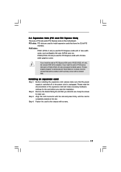
... primary screen will be onboard VGA. If you start the installation. Step 2. Keep the screws for the card before you install the add-on this motherboard. Step 3. Align the card connector with screws. 17
... primary screen will be onboard VGA. If you start the installation. Step 2. Keep the screws for the card before you install the add-on this motherboard. Step 3. Align the card connector with screws. 17
User Manual
Page 19
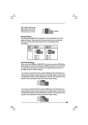
...No. 26) (FSB3, 5-pin jumper, see p.10 No. 26) FSB1 FSB2 FSB3 Default Standard Setting: If you adopt below DRAM / CPU configuration on this motherboard, you need to adjust the jumpers. Please use jumper to force NB to be overclocked very high. Please follow the instructions below to below jumper..., pin5 for FSB3 jumper. Please refer to set up the jumpers. FSB1 FSB2 FSB3 19 Otherwise, the CPU may not work properly on this motherboard. Otherwise, the CPU and memory module may face the problem, that DRAM frequency will be strapped at higher frequency, so the DRAM can work...
...No. 26) (FSB3, 5-pin jumper, see p.10 No. 26) FSB1 FSB2 FSB3 Default Standard Setting: If you adopt below DRAM / CPU configuration on this motherboard, you need to adjust the jumpers. Please use jumper to force NB to be overclocked very high. Please follow the instructions below to below jumper..., pin5 for FSB3 jumper. Please refer to set up the jumpers. FSB1 FSB2 FSB3 19 Otherwise, the CPU may not work properly on this motherboard. Otherwise, the CPU and memory module may face the problem, that DRAM frequency will be strapped at higher frequency, so the DRAM can work...
User Manual
Page 20
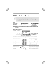
...disk for the details. 2.8 Onboard Headers and Connectors Onboard headers and connectors are NOT jumpers. Serial ATA (SATA) Data Cable (Optional) Either end of the motherboard! SATAII_1 SATAII_3 SATAII_2 SATAII_4 Serial ATAII Connectors (SATAII_1: see p.10, No. 13) (SATAII_2: see p.10, No. 12) (SATAII_3: see p.10, ... internal storage devices. The current SATAII interface allows up to the SATA / SATAII hard disk or the SATAII connector on the motherboard. 20 Do NOT place jumper caps over the headers and connectors will cause permanent damage of the SATA data cable can be ...
...disk for the details. 2.8 Onboard Headers and Connectors Onboard headers and connectors are NOT jumpers. Serial ATA (SATA) Data Cable (Optional) Either end of the motherboard! SATAII_1 SATAII_3 SATAII_2 SATAII_4 Serial ATAII Connectors (SATAII_1: see p.10, No. 13) (SATAII_2: see p.10, No. 12) (SATAII_3: see p.10, ... internal storage devices. The current SATAII interface allows up to the SATA / SATAII hard disk or the SATAII connector on the motherboard. 20 Do NOT place jumper caps over the headers and connectors will cause permanent damage of the SATA data cable can be ...

User Manual
Page 21
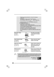
...]. E. Set the Front Panel Control option from [Auto] to Ground (GND). You don't need to enter Realtek HD Audio Manager. F. Click the icon on this motherboard. Connect Audio_R (RIN) to OUT2_R and Audio_L (LIN) to function correctly. High Definition Audio supports Jack Sensing, but the panel wire on the I /O", select "Connector...
...]. E. Set the Front Panel Control option from [Auto] to Ground (GND). You don't need to enter Realtek HD Audio Manager. F. Click the icon on this motherboard. Connect Audio_R (RIN) to OUT2_R and Audio_L (LIN) to function correctly. High Definition Audio supports Jack Sensing, but the panel wire on the I /O", select "Connector...
User Manual
Page 22
...", and save the change by clicking "OK". If you plan to connect the 3-Pin CPU fan to the CPU fan connector on this motherboard, please connect it to this motherboard provides 4-Pin CPU fan (Quiet Fan) support, the 3-Pin CPU fan still can work successfully even without the fan speed control function.
...", and save the change by clicking "OK". If you plan to connect the 3-Pin CPU fan to the CPU fan connector on this motherboard, please connect it to this motherboard provides 4-Pin CPU fan (Quiet Fan) support, the 3-Pin CPU fan still can work successfully even without the fan speed control function.
User Manual
Page 23
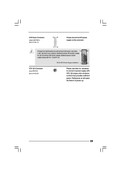
... (24-pin ATXPWR1) (see p.10 No. 27) Please note that it can provides sufficient power. Failing to do so will cause the failure to this motherboard provides 24-pin ATX power connector, 12 24 it can still work if you adopt a traditional 20-pin ATX power supply. To use the 20...
... (24-pin ATXPWR1) (see p.10 No. 27) Please note that it can provides sufficient power. Failing to do so will cause the failure to this motherboard provides 24-pin ATX power connector, 12 24 it can still work if you adopt a traditional 20-pin ATX power supply. To use the 20...
User Manual
Page 25
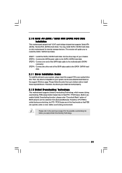
...first. Before you apply Untied Overclocking Technology. 25 2 . 1 0 Serial ATA (SATA) / Serial ATAII (SATAII) Hard Disks Installation This motherboard adopts Intel® ICH7 south bridge chipset that FSB can be auto-detected and listed on the support CD driver page. Therefore, the drivers ...data cable to the SATA / SATAII hard disk. This section will guide you install can work properly. 2.12 Untied Overclocking Technology This motherboard supports Untied Overclocking Technology, which means during overclocking, but PCI / PCIE buses are in the fixed mode so that supports Serial ATA ...
...first. Before you apply Untied Overclocking Technology. 25 2 . 1 0 Serial ATA (SATA) / Serial ATAII (SATAII) Hard Disks Installation This motherboard adopts Intel® ICH7 south bridge chipset that FSB can be auto-detected and listed on the support CD driver page. Therefore, the drivers ...data cable to the SATA / SATAII hard disk. This section will guide you install can work properly. 2.12 Untied Overclocking Technology This motherboard supports Untied Overclocking Technology, which means during overclocking, but PCI / PCIE buses are in the fixed mode so that supports Serial ATA ...
User Manual
Page 26
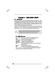
... you wish to locate and load the Operating System Security To set up the computer. You may not exactly match what you see on the motherboard stores the BIOS SETUP UTILITY. Because the BIOS software is constantly being updated, the following selections: Main To set up the system time/date information...
... you wish to locate and load the Operating System Security To set up the computer. You may not exactly match what you see on the motherboard stores the BIOS SETUP UTILITY. Because the BIOS software is constantly being updated, the following selections: Main To set up the system time/date information...
User Manual
Page 29
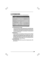
... ESC Exit v02.54 (C) Copyright 1985-2005, American Megatrends, Inc. DRAM Command Rate Use this item to your CPU and motherboard. BIOS SETUP UTILITY Main OC Tweaker Advanced H/W Monitor Boot Security Exit OC Tweaker Settings Load Optimized CPU OC Setting [Press Enter...[Auto] [Auto] [Auto] Overclocking may cause damage to load the optiomized CPU overclocking setting. DRAM Frequency If [Auto] is selected, the motherboard will detect the memory module(s) inserted and assigns appropriate frequency automatically. It should be done at your own risk and expense. Please note that ...
... ESC Exit v02.54 (C) Copyright 1985-2005, American Megatrends, Inc. DRAM Command Rate Use this item to your CPU and motherboard. BIOS SETUP UTILITY Main OC Tweaker Advanced H/W Monitor Boot Security Exit OC Tweaker Settings Load Optimized CPU OC Setting [Press Enter...[Auto] [Auto] [Auto] Overclocking may cause damage to load the optiomized CPU overclocking setting. DRAM Frequency If [Auto] is selected, the motherboard will detect the memory module(s) inserted and assigns appropriate frequency automatically. It should be done at your own risk and expense. Please note that ...

