User Manual
Page 3
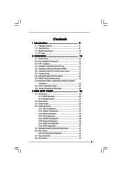
... Guide 24 2.10 Serial ATA (SATA) / Serial ATAII (SATAII) Hard Disks Installation 25 2.11 Driver Installation Guide 25 2.12 Untied Overclocking Technology 25 3 BIOS SETUP UTILITY 26 3.1 Introduction 26 3.1.1 BIOS Menu Bar 26 3.1.2 Navigation Keys 27 3.2 Main Screen 27 3.3 Smart Screen 29 3.4 Advanced Screen 30 3.4.1 CPU Configuration 30 3.4.2 Chipset Configuration 32 3.4.3 ACPI...
... Guide 24 2.10 Serial ATA (SATA) / Serial ATAII (SATAII) Hard Disks Installation 25 2.11 Driver Installation Guide 25 2.12 Untied Overclocking Technology 25 3 BIOS SETUP UTILITY 26 3.1 Introduction 26 3.1.1 BIOS Menu Bar 26 3.1.2 Navigation Keys 27 3.2 Main Screen 27 3.3 Smart Screen 29 3.4 Advanced Screen 30 3.4.1 CPU Configuration 30 3.4.2 Chipset Configuration 32 3.4.3 ACPI...
User Manual
Page 5
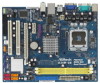
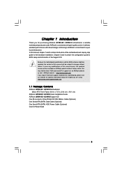
... without notice. Because the motherboard specifications and the BIOS software might be updated, the content of this manual, chapter 1 and 2 contain introduction of this motherboard, please visit our website for specific information about the model you for purchasing ASRock G31M-GS / G31M-S motherboard, a reliable motherboard produced under ASRock's consistently stringent quality control. Chapter 1 Introduction Thank you...
... without notice. Because the motherboard specifications and the BIOS software might be updated, the content of this manual, chapter 1 and 2 contain introduction of this motherboard, please visit our website for specific information about the model you for purchasing ASRock G31M-GS / G31M-S motherboard, a reliable motherboard produced under ASRock's consistently stringent quality control. Chapter 1 Introduction Thank you...
User Manual
Page 7
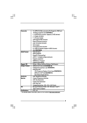
... ports) (see CAUTION 11) - Intelligent Energy Saver (see CAUTION 9) BIOS Feature - 4Mb AMI BIOS - CPU Fan Tachometer - Chassis Fan Tachometer - CPU Quiet Fan - ACPI 1.1 Compliance Wake Up Events - ASRock U-COP (see CAUTION 10) - CPU Temperature Sensing Monitor - Microsoft®...Supports "Plug and Play" - Supports jumperfree - AMBIOS 2.3.1 Support - Hybrid Booster: - Boot Failure Guard (B.F.G.) Hardware - Supports Smart BIOS Support CD - ASRock OC Tuner (see CAUTION 13) - Connector - 4 x SATAII 3.0 Gb/s connectors (No Support for RAID and "Hot Plug" ...
... ports) (see CAUTION 11) - Intelligent Energy Saver (see CAUTION 9) BIOS Feature - 4Mb AMI BIOS - CPU Fan Tachometer - Chassis Fan Tachometer - CPU Quiet Fan - ACPI 1.1 Compliance Wake Up Events - ASRock U-COP (see CAUTION 10) - CPU Temperature Sensing Monitor - Microsoft®...Supports "Plug and Play" - Supports jumperfree - AMBIOS 2.3.1 Support - Hybrid Booster: - Boot Failure Guard (B.F.G.) Hardware - Supports Smart BIOS Support CD - ASRock OC Tuner (see CAUTION 13) - Connector - 4 x SATAII 3.0 Gb/s connectors (No Support for RAID and "Hot Plug" ...
User Manual
Page 8
...Dual Channel Memory Technology, make sure to get the best system performance under Windows® XP and Windows® VistaTM. ASRock website: http://www.asrock.com 8 You can also connect SATA hard disk to change. Before installing SATAII hard disk to SATAII connector, please read... the installation guide of "Hyper Threading Technology", please check page 32. 3. Under this situation, PCIE frequency will operate in the BIOS, applying...
...Dual Channel Memory Technology, make sure to get the best system performance under Windows® XP and Windows® VistaTM. ASRock website: http://www.asrock.com 8 You can also connect SATA hard disk to change. Before installing SATAII hard disk to SATAII connector, please read... the installation guide of "Hyper Threading Technology", please check page 32. 3. Under this situation, PCIE frequency will operate in the BIOS, applying...
User Manual
Page 10
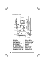
... 1 LAN PHY PCIE1 CMOS Battery CLRCMOS1 IDE1 Super IO CD1 RoHS AUDIO CODEC HD_AUDIO1 FLOPPY1 1 21 20 PCIE2 SATAII_3 PCI1 Intel ICH7 PCI2 CHA_FAN1 4Mb BIOS PANEL 1 PLED PWRBTN 1 HDLED RESET USB4_5 1 USB6_7 1 SPEAKER1 1 SATAII_1 19 18 17 16 15 14 13 12 SATAII_2 SATAII_4 6 7 8 9 10 11 1 ... 2 775-Pin CPU Socket 16 USB 2.0 Header (USB4_5, Blue) 3 North Bridge Controller 17 System Panel Header (PANEL1, Orange) 4 CPU Fan Connector (CPU_FAN1) 18 BIOS SPI Chip 5 2 x 240-pin DDR2 DIMM Slots 19 Chassis Fan Connector (CHA_FAN1) (Dual Channel: DDRII_1, DDRII_2;
... 1 LAN PHY PCIE1 CMOS Battery CLRCMOS1 IDE1 Super IO CD1 RoHS AUDIO CODEC HD_AUDIO1 FLOPPY1 1 21 20 PCIE2 SATAII_3 PCI1 Intel ICH7 PCI2 CHA_FAN1 4Mb BIOS PANEL 1 PLED PWRBTN 1 HDLED RESET USB4_5 1 USB6_7 1 SPEAKER1 1 SATAII_1 19 18 17 16 15 14 13 12 SATAII_2 SATAII_4 6 7 8 9 10 11 1 ... 2 775-Pin CPU Socket 16 USB 2.0 Header (USB4_5, Blue) 3 North Bridge Controller 17 System Panel Header (PANEL1, Orange) 4 CPU Fan Connector (CPU_FAN1) 18 BIOS SPI Chip 5 2 x 240-pin DDR2 DIMM Slots 19 Chassis Fan Connector (CHA_FAN1) (Dual Channel: DDRII_1, DDRII_2;
User Manual
Page 17
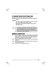
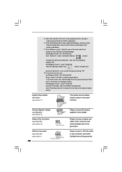
... off or the power cord is completely seated on PCI Express VGA card to PCIE2 (PCIE x16 slot) and adjust the "Internal Graphics Mode Select" BIOS option to the chassis with x16 lane width graphics cards. Keep the screws for the card before you install the add-on the slot. Align...
... off or the power cord is completely seated on PCI Express VGA card to PCIE2 (PCIE x16 slot) and adjust the "Internal Graphics Mode Select" BIOS option to the chassis with x16 lane width graphics cards. Keep the screws for the card before you install the add-on the slot. Align...
User Manual
Page 22
... front panel jack detection", and save the change by clicking "OK". To activate the front mic. Enter Advanced Settings, and then select Chipset Configuration. G. Enter BIOS Setup Utility. Click the icon on the lower right hand taskbar to the ground pin. For Windows® VistaTM / VistaTM 64-bit OS: Click the...
... front panel jack detection", and save the change by clicking "OK". To activate the front mic. Enter Advanced Settings, and then select Chipset Configuration. G. Enter BIOS Setup Utility. Click the icon on the lower right hand taskbar to the ground pin. For Windows® VistaTM / VistaTM 64-bit OS: Click the...
User Manual
Page 25
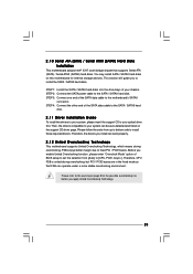
..., but PCI / PCIE buses are in the fixed mode so that supports Serial ATA (SATA) / Serial ATAII (SATAII) hard disks. STEP 3: Connect one end of BIOS setup to set the selection from up to bottom side to your system can operate under a more stable overclocking environment. Then, the drivers compatible to...
..., but PCI / PCIE buses are in the fixed mode so that supports Serial ATA (SATA) / Serial ATAII (SATAII) hard disks. STEP 3: Connect one end of BIOS setup to set the selection from up to bottom side to your system can operate under a more stable overclocking environment. Then, the drivers compatible to...

User Manual
Page 26
... the default system device to locate and load the Operating System Security To set up the security features Chipset To set up the computer. The BIOS FWH chip on the menu bar, and then press to get into the sub screen. 26 If you start up the chipset features Exit To... exactly match what you see on your system. Please press during the Power-On-Self-Test (POST) to enter the BIOS SETUP UTILITY, otherwise, POST will continue with the following BIOS setup screens and descriptions are for reference purpose only, and they may also restart by pressing the reset button on . ...
... the default system device to locate and load the Operating System Security To set up the security features Chipset To set up the computer. The BIOS FWH chip on the menu bar, and then press to get into the sub screen. 26 If you start up the chipset features Exit To... exactly match what you see on your system. Please press during the Power-On-Self-Test (POST) to enter the BIOS SETUP UTILITY, otherwise, POST will continue with the following BIOS setup screens and descriptions are for reference purpose only, and they may also restart by pressing the reset button on . ...
User Manual
Page 27
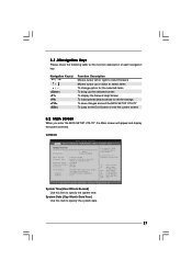
...To jump to the Exit Screen or exit the current screen 3.2 Main Screen When you enter the BIOS SETUP UTILITY, the Main screen will appear and display the system overview G31M-GS BIOS SETUP UTILITY Main Smart Advanced H/W Monitor Boot Security Exit System Overview System Time System Date [14:00...:09] [Thu 07/31/2008] BIOS Version : G31M-GS P1.00 Processor Type : Intel(R) Core(TM) 2 Duo CPU E6540 @ 2.33GHz (64bit) Processor Speed : 2333MHz Microcode Update : 6FB/B6 Cache Size :...
...To jump to the Exit Screen or exit the current screen 3.2 Main Screen When you enter the BIOS SETUP UTILITY, the Main screen will appear and display the system overview G31M-GS BIOS SETUP UTILITY Main Smart Advanced H/W Monitor Boot Security Exit System Overview System Time System Date [14:00...:09] [Thu 07/31/2008] BIOS Version : G31M-GS P1.00 Processor Type : Intel(R) Core(TM) 2 Duo CPU E6540 @ 2.33GHz (64bit) Processor Speed : 2333MHz Microcode Update : 6FB/B6 Cache Size :...
User Manual
Page 28
...the system time. System Date [Day Month/Date/Year] Use this item to specify the system date. 28 Use [+] or [-] to select a field. G31M-S BIOS SETUP UTILITY Main Smart Advanced H/W Monitor Boot Security Exit System Overview System Time System Date [14:00:09] [Thu 07/31/2008...] BIOS Version : G31M-S P1.00 Processor Type : Intel(R) Core(TM) 2 Duo CPU E6540 @ 2.33GHz (64bit) Processor Speed : 2333MHz Microcode Update : 6FB/B6 Cache Size : 4096KB Total ...
...the system time. System Date [Day Month/Date/Year] Use this item to specify the system date. 28 Use [+] or [-] to select a field. G31M-S BIOS SETUP UTILITY Main Smart Advanced H/W Monitor Boot Security Exit System Overview System Time System Date [14:00:09] [Thu 07/31/2008...] BIOS Version : G31M-S P1.00 Processor Type : Intel(R) Core(TM) 2 Duo CPU E6540 @ 2.33GHz (64bit) Processor Speed : 2333MHz Microcode Update : 6FB/B6 Cache Size : 4096KB Total ...
User Manual
Page 29
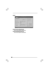
...F9 key can be used for this operation. F5 key can be used for this operation. BIOS SETUP UTILITY Main Smart Advanced H/W Monitor Boot Security Exit Smart Settings Save Changes and Exit Load BIOS Defaults Load Performance Setup Default (IDE/SATA) Load Power Saving Setup Default Exit system setup after... occurs after saving the changes. Save Changes and Exit When you can be compatible with all the setup questions. F6 key can load the BIOS setup according to your requirements. Select [OK] to Sub Screen F1 General Help F9 Load Defaults F10 Save and Exit ESC Exit v02.54...
...F9 key can be used for this operation. F5 key can be used for this operation. BIOS SETUP UTILITY Main Smart Advanced H/W Monitor Boot Security Exit Smart Settings Save Changes and Exit Load BIOS Defaults Load Performance Setup Default (IDE/SATA) Load Power Saving Setup Default Exit system setup after... occurs after saving the changes. Save Changes and Exit When you can be compatible with all the setup questions. F6 key can load the BIOS setup according to your requirements. Select [OK] to Sub Screen F1 General Help F9 Load Defaults F10 Save and Exit ESC Exit v02.54...
User Manual
Page 30
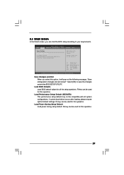
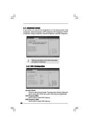
...Select Item Change Option General Help Load Defaults Save and Exit Exit v02.54 (C) Copyright 1985-2005, American Megatrends, Inc. BIOS SETUP UTILITY Main Smart Advanced H/W Monitor Boot Security Exit Advanced Settings WARNING : Setting wrong values in this section may cause the... 1985-2005, American Megatrends, Inc. PCIE Frequency (MHz) Use this section, you may cause system to malfunction. 3.4.1 CPU Configuration BIOS SETUP UTILITY Advanced CPU Configuration Overclock Mode CPU Frequency (MHz) PCIE Frequency (MHz) Boot Failure Guard Spread Spectrum Ratio Actual Value Enhance...
...Select Item Change Option General Help Load Defaults Save and Exit Exit v02.54 (C) Copyright 1985-2005, American Megatrends, Inc. BIOS SETUP UTILITY Main Smart Advanced H/W Monitor Boot Security Exit Advanced Settings WARNING : Setting wrong values in this section may cause the... 1985-2005, American Megatrends, Inc. PCIE Frequency (MHz) Use this section, you may cause system to malfunction. 3.4.1 CPU Configuration BIOS SETUP UTILITY Advanced CPU Configuration Overclock Mode CPU Frequency (MHz) PCIE Frequency (MHz) Boot Failure Guard Spread Spectrum Ratio Actual Value Enhance...
User Manual
Page 32
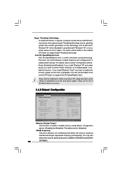
... enable or disable memory remap feature. Intel (R) SpeedStep(tm) tech. If you need to set this item to [Disable] if above issue occurs. 3.4.2 Chipset Configuration BIOS SETUP UTILITY Advanced Chipset Configuration Memory Remap Feature DRAM Frequency Flexibility Option DRAM tCL DRAM tRCD DRAM tRP DRAM tRAS [Disabled] [Auto] [Disabled] [Auto] [Auto...
... enable or disable memory remap feature. Intel (R) SpeedStep(tm) tech. If you need to set this item to [Disable] if above issue occurs. 3.4.2 Chipset Configuration BIOS SETUP UTILITY Advanced Chipset Configuration Memory Remap Feature DRAM Frequency Flexibility Option DRAM tCL DRAM tRCD DRAM tRP DRAM tRAS [Disabled] [Auto] [Disabled] [Auto] [Auto...

User Manual
Page 34
...] and [1.5651V]. Configuration options: [Auto], [Enabled] and [Disabled]. If you can also choose our Intelligent Energy Saver utility to enable this to [Enabled]. Besides the BIOS option, you want to adjust DRAM RCOMP Setting feature. NB Voltage Use this function. Configuration options: [Auto] and [Manual]. The default value of this feature...
...] and [1.5651V]. Configuration options: [Auto], [Enabled] and [Disabled]. If you can also choose our Intelligent Energy Saver utility to enable this to [Enabled]. Besides the BIOS option, you want to adjust DRAM RCOMP Setting feature. NB Voltage Use this function. Configuration options: [Auto] and [Manual]. The default value of this feature...
User Manual
Page 35
3.4.3 ACPI Configuration BIOS SETUP UTILITY Advanced ACPI Configuration Suspend To RAM Restore on the system from the power-soft-off mode. Restore on AC/Power Loss This allows ...
3.4.3 ACPI Configuration BIOS SETUP UTILITY Advanced ACPI Configuration Suspend To RAM Restore on the system from the power-soft-off mode. Restore on AC/Power Loss This allows ...
User Manual
Page 36
...] when you to [SATA 1, SATA 3, IDE 1], then SATAII_2, SATAII_4 will use the "Primary IDE Master" as the example in the following instruction. 36 3.4.4 IDE Configuration BIOS SETUP UTILITY Advanced IDE Configuration ATA/IDE Configuration SATAII 1 SATAII 2 SATAII 3 SATAII 4 IDE1 Master IDE1 Slave [Enhanced] [Hard Disk] [Not Detected] [Not Detected] [Not Detected...
...] when you to [SATA 1, SATA 3, IDE 1], then SATAII_2, SATAII_4 will use the "Primary IDE Master" as the example in the following instruction. 36 3.4.4 IDE Configuration BIOS SETUP UTILITY Advanced IDE Configuration ATA/IDE Configuration SATAII 1 SATAII 2 SATAII 3 SATAII 4 IDE1 Master IDE1 Slave [Enhanced] [Hard Disk] [Not Detected] [Not Detected] [Not Detected...
User Manual
Page 37
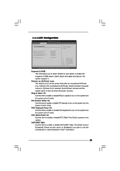
... this item to set the partition of IDE device. [Auto]: Select [Auto] to disable the LBA/Large mode. After selecting the hard disk information into BIOS, use of the Primary IDE hard disk drives to the system. +F1 F9 F10 ESC Select Screen Select Item Change Option General Help Load Defaults... active. [CD/DVD]: This is used for IDE CD/DVD drives. [ARMD]: This is [Auto]. If this item is used for compatible IDE devices. 37 BIOS SETUP UTILITY Advanced Primary IDE Master Device Vendor Size LBA Mode Block Mode PIO Mode Async DMA Ultra DMA S.M.A.R.T. PIO Mode Use this item to...
... this item to set the partition of IDE device. [Auto]: Select [Auto] to disable the LBA/Large mode. After selecting the hard disk information into BIOS, use of the Primary IDE hard disk drives to the system. +F1 F9 F10 ESC Select Screen Select Item Change Option General Help Load Defaults... active. [CD/DVD]: This is used for IDE CD/DVD drives. [ARMD]: This is [Auto]. If this item is used for compatible IDE devices. 37 BIOS SETUP UTILITY Advanced Primary IDE Master Device Vendor Size LBA Mode Block Mode PIO Mode Async DMA Ultra DMA S.M.A.R.T. PIO Mode Use this item to...
User Manual
Page 38
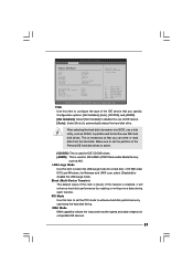
... enable or disable the S.M.A.R.T. (Self-Monitoring, Analysis, and Reporting Technology) feature. Use this item to maximize the IDE hard disk data transfer rate. 3.4.5 PCIPnP Configuration BIOS SETUP UTILITY Advanced Advanced PCI / PnP Settings PCI Latency Timer PCI IDE BusMaster [32] [Enabled] Value in units of PCI clocks for PCI device latency...
... enable or disable the S.M.A.R.T. (Self-Monitoring, Analysis, and Reporting Technology) feature. Use this item to maximize the IDE hard disk data transfer rate. 3.4.5 PCIPnP Configuration BIOS SETUP UTILITY Advanced Advanced PCI / PnP Settings PCI Latency Timer PCI IDE BusMaster [32] [Enabled] Value in units of PCI clocks for PCI device latency...
User Manual
Page 39
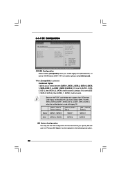
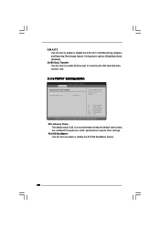
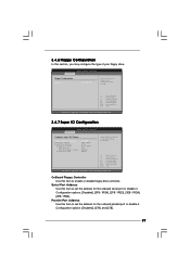
... the onboard serial port or disable it . Configuration options: [Disabled], [3F8 / IRQ4], [2F8 / IRQ3], [3E8 / IRQ4], [2E8 / IRQ3]. BIOS SETUP UTILITY Advanced Floppy Configuration Floppy A [1.44 MB 312"] Select the type of your floppy drive. Configuration options: [Disabled], [378], and [278]. 39... Help Load Defaults Save and Exit Exit v02.54 (C) Copyright 1985-2005, American Megatrends, Inc. 3.4.7 Super IO Configuration BIOS SETUP UTILITY Advanced Configure Super IO Chipset OnBoard Floppy Controller Serial Port Address Parallel Port Address Parallel Port Mode EPP Version ECP...
... the onboard serial port or disable it . Configuration options: [Disabled], [3F8 / IRQ4], [2F8 / IRQ3], [3E8 / IRQ4], [2E8 / IRQ3]. BIOS SETUP UTILITY Advanced Floppy Configuration Floppy A [1.44 MB 312"] Select the type of your floppy drive. Configuration options: [Disabled], [378], and [278]. 39... Help Load Defaults Save and Exit Exit v02.54 (C) Copyright 1985-2005, American Megatrends, Inc. 3.4.7 Super IO Configuration BIOS SETUP UTILITY Advanced Configure Super IO Chipset OnBoard Floppy Controller Serial Port Address Parallel Port Address Parallel Port Mode EPP Version ECP...


