

User Manual
Page 6
...1.3 Motherboard Layout 6 1.4 I/O Panel 8 Chapter 2 Installation 10 2.1 Installing the CPU 11 2.2 Installing the CPU Fan and Heatsink 14 2.3 Installation of Memory Modules (DIMM) 15 2.4 Expansion Slots (PCI Express Slots) 17 2.5 Jumpers Setup 18 2.6 Onboard Headers and Connectors 19 2.7 Smart Switches 24 2.8 Dr. Debug 25 2.9 SLITM and Quad SLITM Operation Guide 27 2.9.1 Installing Two SLITM-Ready Graphics Cards 27 2.9.2 Driver Installation and Setup 29 2.10 CrossFireXTM and Quad CrossFireXTM Operation Guide 30 2.10.1 Installing Two CrossFireXTM-Ready Graphics Cards...
...1.3 Motherboard Layout 6 1.4 I/O Panel 8 Chapter 2 Installation 10 2.1 Installing the CPU 11 2.2 Installing the CPU Fan and Heatsink 14 2.3 Installation of Memory Modules (DIMM) 15 2.4 Expansion Slots (PCI Express Slots) 17 2.5 Jumpers Setup 18 2.6 Onboard Headers and Connectors 19 2.7 Smart Switches 24 2.8 Dr. Debug 25 2.9 SLITM and Quad SLITM Operation Guide 27 2.9.1 Installing Two SLITM-Ready Graphics Cards 27 2.9.2 Driver Installation and Setup 29 2.10 CrossFireXTM and Quad CrossFireXTM Operation Guide 30 2.10.1 Installing Two CrossFireXTM-Ready Graphics Cards...
User Manual
Page 9
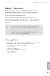
... Fatal1ty X99M Killer/3.1 Series Quick Installation Guide • ASRock Fatal1ty X99M Killer/3.1 Series Support CD • 1 x I/O Panel Shield • 1 x ASRock SLI_Bridge Card • 2 x Serial ATA (SATA) Data Cables (Optional) • 1 x HDD Saver Cable • 1 x Screw for purchasing ASRock Fatal1ty X99M Killer/3.1 Series motherboard, a reliable motherboard produced under ASRock's consistently stringent quality control. You may ind the latest VGA cards and CPU support list on ASRock's website without notice. Chapter 3 contains the operation guide of the sotware and utilities...
... Fatal1ty X99M Killer/3.1 Series Quick Installation Guide • ASRock Fatal1ty X99M Killer/3.1 Series Support CD • 1 x I/O Panel Shield • 1 x ASRock SLI_Bridge Card • 2 x Serial ATA (SATA) Data Cables (Optional) • 1 x HDD Saver Cable • 1 x Screw for purchasing ASRock Fatal1ty X99M Killer/3.1 Series motherboard, a reliable motherboard produced under ASRock's consistently stringent quality control. You may ind the latest VGA cards and CPU support list on ASRock's website without notice. Chapter 3 contains the operation guide of the sotware and utilities...

User Manual
Page 12
... PCI Express module up to Gen3 x4 (32 Gb/s) Connector • 1 x COM Port Header • 1 x TPM Header • 1 x Power LED Header • 2 x CPU Fan Connectors (1 x 4-pin, 1 x 3-pin) • 2 x Chassis Fan Connectors (1 x 4-pin, 1 x 3-pin) (Smart Fan Speed Control) • 1 x Power Fan Connector (3-pin) • 1 x 24 pin ATX Power Connector • 1 x 8 pin 12V Power Connector (Hi-Density Power Connector) • 1 x HDD Saver Connector • 1 x PCIe Power Connector • 1 x Front Panel Audio Connector • 1 x hunderbolt AIC Connector • 2 x USB 2.0 Headers (support...
... PCI Express module up to Gen3 x4 (32 Gb/s) Connector • 1 x COM Port Header • 1 x TPM Header • 1 x Power LED Header • 2 x CPU Fan Connectors (1 x 4-pin, 1 x 3-pin) • 2 x Chassis Fan Connectors (1 x 4-pin, 1 x 3-pin) (Smart Fan Speed Control) • 1 x Power Fan Connector (3-pin) • 1 x 24 pin ATX Power Connector • 1 x 8 pin 12V Power Connector (Hi-Density Power Connector) • 1 x HDD Saver Connector • 1 x PCIe Power Connector • 1 x Front Panel Audio Connector • 1 x hunderbolt AIC Connector • 2 x USB 2.0 Headers (support...

User Manual
Page 13
... visit our website: http://www.asrock.com Please realize that Windows® cannot use ASRock XFast RAM to the components and devices of your own risk and expense. adjustment • CPU/Chassis temperature sensing • CPU/Chassis/Power Fan Tachometer • CPU/Chassis Quiet Fan (Auto adjust chassis fan speed by overclocking. Fatal1ty X99M Killer/3.1 Series Hardware Monitor OS Certiications • SMBIOS 2.3.1 Support • CPU, DRAM, PCH 1.05V, PCH 1.5V, VPPM Voltage Multi- You can use . English 5 We are not responsible...
... visit our website: http://www.asrock.com Please realize that Windows® cannot use ASRock XFast RAM to the components and devices of your own risk and expense. adjustment • CPU/Chassis temperature sensing • CPU/Chassis/Power Fan Tachometer • CPU/Chassis Quiet Fan (Auto adjust chassis fan speed by overclocking. Fatal1ty X99M Killer/3.1 Series Hardware Monitor OS Certiications • SMBIOS 2.3.1 Support • CPU, DRAM, PCH 1.05V, PCH 1.5V, VPPM Voltage Multi- You can use . English 5 We are not responsible...
User Manual
Page 15
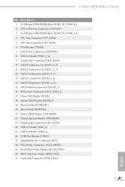
...) 15 SATA Express Connector (SATAE_1) 16 HDD Saver Connector (SATA_PWR_1) 17 Power LED Header (PLED1) 18 System Panel Header (PANEL1) 19 Power Switch (PWRBTN1) 20 Reset Switch (RSTBTN1) 21 Clear CMOS Jumper (CLRCMOS1) 22 Chassis Speaker Header (SPEAKER1) 23 Chassis Fan Connector (CHA_FAN1) 24 USB 2.0 Header (USB7_8) 25 USB 2.0 Header (USB5_6) 26 COM Port Header (COM1) 27 hunderbolt AIC Connector (TBT1) 28 PCIe Power Connector (PCIE_PWR1) 29 Front Panel Audio Header (HD_AUDIO1) 30 BIOS Selection Switch (BIOS_SEL1) 31 Power Fan Connector (PWR_FAN1) 7 English Fatal1ty X99M Killer/3.1 Series No.
...) 15 SATA Express Connector (SATAE_1) 16 HDD Saver Connector (SATA_PWR_1) 17 Power LED Header (PLED1) 18 System Panel Header (PANEL1) 19 Power Switch (PWRBTN1) 20 Reset Switch (RSTBTN1) 21 Clear CMOS Jumper (CLRCMOS1) 22 Chassis Speaker Header (SPEAKER1) 23 Chassis Fan Connector (CHA_FAN1) 24 USB 2.0 Header (USB7_8) 25 USB 2.0 Header (USB5_6) 26 COM Port Header (COM1) 27 hunderbolt AIC Connector (TBT1) 28 PCIe Power Connector (PCIE_PWR1) 29 Front Panel Audio Header (HD_AUDIO1) 30 BIOS Selection Switch (BIOS_SEL1) 31 Power Fan Connector (PWR_FAN1) 7 English Fatal1ty X99M Killer/3.1 Series No.

User Manual
Page 31
... TTXD1 DDCD#1 his connector supports Trusted Platform Module (TPM) system, which can securely store keys, digital certiicates, passwords, and data. Please connect the HDD Saver Cable to this connector when more than three graphics cards are installed. Fatal1ty X99M Killer/3.1 Series PCIe Power Connector (4-pin PCIE_PWR1) (see p.6, No. 28) HDD Saver Connector (4-pin SATA_PWR_1) (see p.6, No. 16) hunderbolt AIC Connector (5-pin TBT1) (see p.6, No. 27) Serial Port Header (9-pin COM1) (see p.6, No. 26) TPM Header (17-pin TPMS1) (see p.6, No...
... TTXD1 DDCD#1 his connector supports Trusted Platform Module (TPM) system, which can securely store keys, digital certiicates, passwords, and data. Please connect the HDD Saver Cable to this connector when more than three graphics cards are installed. Fatal1ty X99M Killer/3.1 Series PCIe Power Connector (4-pin PCIE_PWR1) (see p.6, No. 28) HDD Saver Connector (4-pin SATA_PWR_1) (see p.6, No. 16) hunderbolt AIC Connector (5-pin TBT1) (see p.6, No. 27) Serial Port Header (9-pin COM1) (see p.6, No. 26) TPM Header (17-pin TPMS1) (see p.6, No...

User Manual
Page 33
... clear CMOS, re-install the memory and VGA card, and remove other slots. Please re-install PCI-E devices or try using other memory modules. Please re-install IDE and SATA devices. b0 Problem related to IDE or SATA devices. Fatal1ty X99M Killer/3.1 Series 2.8 Dr. Debug Dr. Debug is installed correctly and then clear CMOS. 0d Problem related to memory, VGA card or other memory modules. 55 he Memory could not be detected. Code Description 00 Please check if the CPU is used to provide code information, which makes troubleshooting...
... clear CMOS, re-install the memory and VGA card, and remove other slots. Please re-install PCI-E devices or try using other memory modules. Please re-install IDE and SATA devices. b0 Problem related to IDE or SATA devices. Fatal1ty X99M Killer/3.1 Series 2.8 Dr. Debug Dr. Debug is installed correctly and then clear CMOS. 0d Problem related to memory, VGA card or other memory modules. 55 he Memory could not be detected. Code Description 00 Please check if the CPU is used to provide code information, which makes troubleshooting...

User Manual
Page 38
... details. 4. You should only use a AMD certiied PSU. If you purchase, not bundled with this motherboard. Please refer to use identical CrossFireXTM-ready graphics cards that your graphics card driver supports AMD CrossFireXTM technology. Please refer to your graphics card vendor for detailed installation guide. 2.10.1 Installing Two CrossFireXTM-Ready Graphics Cards Step 1 Insert one graphics card into PCIE1 slot and the other graphics card to two identical PCI Express x16 graphics cards. Currently CrossFireXTM and Quad CrossFireXTM...
... details. 4. You should only use a AMD certiied PSU. If you purchase, not bundled with this motherboard. Please refer to use identical CrossFireXTM-ready graphics cards that your graphics card driver supports AMD CrossFireXTM technology. Please refer to your graphics card vendor for detailed installation guide. 2.10.1 Installing Two CrossFireXTM-Ready Graphics Cards Step 1 Insert one graphics card into PCIE1 slot and the other graphics card to two identical PCI Express x16 graphics cards. Currently CrossFireXTM and Quad CrossFireXTM...

User Manual
Page 40
... VGA drivers installed in the Windows® system tray. he Catalyst Uninstaller is an optional download. AMD Catalyst Control Center Step 4 Double-click the AMD Catalyst Control Center icon in your computer. hen select Enable AMD CrossFireX and click Apply. Please check AMD's website for AMD driver updates. Step 3 Install the required drivers and CATALYST Control Center then restart your system. Select the GPU number according to installation. Step 2 Remove the AMD drivers...
... VGA drivers installed in the Windows® system tray. he Catalyst Uninstaller is an optional download. AMD Catalyst Control Center Step 4 Double-click the AMD Catalyst Control Center icon in your computer. hen select Enable AMD CrossFireX and click Apply. Please check AMD's website for AMD driver updates. Step 3 Install the required drivers and CATALYST Control Center then restart your system. Select the GPU number according to installation. Step 2 Remove the AMD drivers...

User Manual
Page 45
Fatal1ty X99M Killer/3.1 Series Chapter 3 Software and Utilities Operation 3.1 Installing Drivers he Utilities Menu shows the application sotware that enhance the motherboard's features. Please click Install All or follow the installation wizard to install those required drivers. To improve Windows 7 compatibility, please download and install the following hot ix provided by Microsot. Utilities Menu he Support CD that comes with the motherboard contains necessary drivers and useful utilities that the motherboard supports. "KB2720599": http://support.microsot.com/kb/2720599/en...
Fatal1ty X99M Killer/3.1 Series Chapter 3 Software and Utilities Operation 3.1 Installing Drivers he Utilities Menu shows the application sotware that enhance the motherboard's features. Please click Install All or follow the installation wizard to install those required drivers. To improve Windows 7 compatibility, please download and install the following hot ix provided by Microsot. Utilities Menu he Support CD that comes with the motherboard contains necessary drivers and useful utilities that the motherboard supports. "KB2720599": http://support.microsot.com/kb/2720599/en...

User Manual
Page 83
... start to enable onboard HD audio and automatically disable it when a sound card is selected, the power will remain of the Power and Keyboard LEDs when the system enters into Standby/Hibernation mode. Set to Auto to boot up when the power recovers. Onboard LAN Enable or disable the onboard network interface controller (Qualcomm® Atheros® KillerTM E2200 Series). If [Power Of] is installed. It will be switched of when the system is shut down. Onboard Debug Port LED Enable/disable the onboard...
... start to enable onboard HD audio and automatically disable it when a sound card is selected, the power will remain of the Power and Keyboard LEDs when the system enters into Standby/Hibernation mode. Set to Auto to boot up when the power recovers. Onboard LAN Enable or disable the onboard network interface controller (Qualcomm® Atheros® KillerTM E2200 Series). If [Power Of] is installed. It will be switched of when the system is shut down. Onboard Debug Port LED Enable/disable the onboard...

User Manual
Page 85
4.4.4 Super IO Coniguration Fatal1ty X99M Killer/3.1 Series Serial Port Enable or disable the Serial port. PS2 Y-Cable Enable the PS2 Y-Cable or set this option to Auto. 77 English Serial Port Address Select the address of the Serial port.
4.4.4 Super IO Coniguration Fatal1ty X99M Killer/3.1 Series Serial Port Enable or disable the Serial port. PS2 Y-Cable Enable the PS2 Y-Cable or set this option to Auto. 77 English Serial Port Address Select the address of the Serial port.

User Manual
Page 87
... BIOS). Set [Enabled] to support USB devices under the UEFI setup and Windows/Linux operating systems only. 79 English Legacy USB Support Enable or disable Legacy OS Support for USB 3.0 devices. Set [Smart Auto] to keep the USB 3.0 driver enabled (Must install driver to disable legacy USB support. If you encounter USB compatibility issues it is recommended to disable the USB 3.0 ports. 4.4.6 USB Coniguration Fatal1ty X99M Killer/3.1 Series USB Controller Enable or disable all the USB ports. If you encounter USB compatibility issues it is recommended to use USB devices...
... BIOS). Set [Enabled] to support USB devices under the UEFI setup and Windows/Linux operating systems only. 79 English Legacy USB Support Enable or disable Legacy OS Support for USB 3.0 devices. Set [Smart Auto] to keep the USB 3.0 driver enabled (Must install driver to disable legacy USB support. If you encounter USB compatibility issues it is recommended to disable the USB 3.0 ports. 4.4.6 USB Coniguration Fatal1ty X99M Killer/3.1 Series USB Controller Enable or disable all the USB ports. If you encounter USB compatibility issues it is recommended to use USB devices...

User Manual
Page 91
... drivers automatically. Please setup network coniguration before using UEFI Tech Service. Easy Driver Installer For users that installs the LAN driver to your USB pen drive before using Internet Flash. *For BIOS backup and recovery purpose, it is a handy tool in your USB storage device and run Instant Flash to update your OS. You can start installing the operating system in your system via the HDD Saver application under your UEFI. Ater copying the drivers please change the SATA mode to RAID...
... drivers automatically. Please setup network coniguration before using UEFI Tech Service. Easy Driver Installer For users that installs the LAN driver to your USB pen drive before using Internet Flash. *For BIOS backup and recovery purpose, it is a handy tool in your USB storage device and run Instant Flash to update your OS. You can start installing the operating system in your system via the HDD Saver application under your UEFI. Ater copying the drivers please change the SATA mode to RAID...

User Manual
Page 92
Internet Setting Enable or disable sound efects in the setup utility. Load User Default Load previously saved user defaults. 84 English Save User Default Type a proile name and press enter to conigure internet connection settings for Internet Flash. Network Coniguration Use this to save your settings as user default. UEFI Download Server Select a server to download the UEFI irmware.
Internet Setting Enable or disable sound efects in the setup utility. Load User Default Load previously saved user defaults. 84 English Save User Default Type a proile name and press enter to conigure internet connection settings for Internet Flash. Network Coniguration Use this to save your settings as user default. UEFI Download Server Select a server to download the UEFI irmware.

Quick Installation Guide
Page 6
...) 14 SATA3 Connectors (SATA3_2_5) 15 SATA Express Connector (SATAE_1) 16 HDD Saver Connector (SATA_PWR_1) 17 Power LED Header (PLED1) 18 System Panel Header (PANEL1) 19 Power Switch (PWRBTN1) 20 Reset Switch (RSTBTN1) 21 Clear CMOS Jumper (CLRCMOS1) 22 Chassis Speaker Header (SPEAKER1) 23 Chassis Fan Connector (CHA_FAN1) 24 USB 2.0 Header (USB7_8) 25 USB 2.0 Header (USB5_6) 26 COM Port Header (COM1) 27 hunderbolt AIC Connector (TBT1) 28 PCIe Power Connector (PCIE_PWR1) 29 Front Panel Audio Header (HD_AUDIO1) 30 BIOS Selection Switch (BIOS_SEL1) 31 Power Fan Connector (PWR_FAN1) 2 English...
...) 14 SATA3 Connectors (SATA3_2_5) 15 SATA Express Connector (SATAE_1) 16 HDD Saver Connector (SATA_PWR_1) 17 Power LED Header (PLED1) 18 System Panel Header (PANEL1) 19 Power Switch (PWRBTN1) 20 Reset Switch (RSTBTN1) 21 Clear CMOS Jumper (CLRCMOS1) 22 Chassis Speaker Header (SPEAKER1) 23 Chassis Fan Connector (CHA_FAN1) 24 USB 2.0 Header (USB7_8) 25 USB 2.0 Header (USB5_6) 26 COM Port Header (COM1) 27 hunderbolt AIC Connector (TBT1) 28 PCIe Power Connector (PCIE_PWR1) 29 Front Panel Audio Header (HD_AUDIO1) 30 BIOS Selection Switch (BIOS_SEL1) 31 Power Fan Connector (PWR_FAN1) 2 English...

Quick Installation Guide
Page 12
... PCI Express module up to Gen3 x4 (32 Gb/s) Connector • 1 x COM Port Header • 1 x TPM Header • 1 x Power LED Header • 2 x CPU Fan Connectors (1 x 4-pin, 1 x 3-pin) • 2 x Chassis Fan Connectors (1 x 4-pin, 1 x 3-pin) (Smart Fan Speed Control) • 1 x Power Fan Connector (3-pin) • 1 x 24 pin ATX Power Connector • 1 x 8 pin 12V Power Connector (Hi-Density Power Connector) • 1 x HDD Saver Connector • 1 x PCIe Power Connector • 1 x Front Panel Audio Connector • 1 x hunderbolt AIC Connector • 2 x USB 2.0 Headers (support...
... PCI Express module up to Gen3 x4 (32 Gb/s) Connector • 1 x COM Port Header • 1 x TPM Header • 1 x Power LED Header • 2 x CPU Fan Connectors (1 x 4-pin, 1 x 3-pin) • 2 x Chassis Fan Connectors (1 x 4-pin, 1 x 3-pin) (Smart Fan Speed Control) • 1 x Power Fan Connector (3-pin) • 1 x 24 pin ATX Power Connector • 1 x 8 pin 12V Power Connector (Hi-Density Power Connector) • 1 x HDD Saver Connector • 1 x PCIe Power Connector • 1 x Front Panel Audio Connector • 1 x hunderbolt AIC Connector • 2 x USB 2.0 Headers (support...

Quick Installation Guide
Page 27
... enhance network security, protects digital identities, and ensures platform integrity. PCIRST# FRAME PCICLK his COM1 header supports a serial port module. English 23 RRXD1 DDTR#1 DDSR#1 CCTS#1 1 RRI#1 RRTS#1 GND TTXD1 DDCD#1 his connector supports Trusted Platform Module (TPM) system, which can securely store keys, digital certiicates, passwords, and data. Please connect the HDD Saver Cable to this connector when more than three graphics cards are installed. Fatal1ty X99M Killer/3.1 Series PCIe Power Connector (4-pin...
... enhance network security, protects digital identities, and ensures platform integrity. PCIRST# FRAME PCICLK his COM1 header supports a serial port module. English 23 RRXD1 DDTR#1 DDSR#1 CCTS#1 1 RRI#1 RRTS#1 GND TTXD1 DDCD#1 his connector supports Trusted Platform Module (TPM) system, which can securely store keys, digital certiicates, passwords, and data. Please connect the HDD Saver Cable to this connector when more than three graphics cards are installed. Fatal1ty X99M Killer/3.1 Series PCIe Power Connector (4-pin...

Quick Installation Guide
Page 29
... the CPU is used to PCI-E devices. Please re-install IDE and SATA devices. A7 Problem related to memory, VGA card or other USB, PCI devices. 01 - 54 (except 0d), 5A- 60 Problem related to memory. Please press reset or clear CMOS. 92 - 99 Problem related to provide code information, which makes troubleshooting even easier. Fatal1ty X99M Killer/3.1 Series 2.8 Dr. Debug Dr. Debug is installed correctly and then clear CMOS. 0d Problem related to IDE or SATA devices. b0 Problem related to memory. If the problem still...
... the CPU is used to PCI-E devices. Please re-install IDE and SATA devices. A7 Problem related to memory, VGA card or other USB, PCI devices. 01 - 54 (except 0d), 5A- 60 Problem related to memory. Please press reset or clear CMOS. 92 - 99 Problem related to provide code information, which makes troubleshooting even easier. Fatal1ty X99M Killer/3.1 Series 2.8 Dr. Debug Dr. Debug is installed correctly and then clear CMOS. 0d Problem related to IDE or SATA devices. b0 Problem related to memory. If the problem still...

RAID Installation Guide
Page 7
... Advanced Storage Coniguration and set the option SATA Mode Selection to complete the process. A. C. Boot your SATA / SATA2 / SATA3 HDDs with just one simple click in UEFI setup. Please note that this document for all models. 2.3 Installing Windows® 8.1 / 8.1 64-bit / 8 / 8 64-bit / 7 / 7 64-bit With RAID Functions If you exit BIOS setup. Press key to set the necessary RAID items in your system. 7 STEP 2: Use ASRock Easy RAID Installer Easy RAID Installer can copy the RAID driver from a support CD...
... Advanced Storage Coniguration and set the option SATA Mode Selection to complete the process. A. C. Boot your SATA / SATA2 / SATA3 HDDs with just one simple click in UEFI setup. Please note that this document for all models. 2.3 Installing Windows® 8.1 / 8.1 64-bit / 8 / 8 64-bit / 7 / 7 64-bit With RAID Functions If you exit BIOS setup. Press key to set the necessary RAID items in your system. 7 STEP 2: Use ASRock Easy RAID Installer Easy RAID Installer can copy the RAID driver from a support CD...


