
RAID Installation Guide
Page 3
... Striping with the data blocks. In the event of a physical drive failure, data can improve the access performance, it contains a complete copy of the "User Manual" in the other drive if one drive fails. RAID 0 (Data Striping) RAID 0 is a method combining two or more hard disk drives into one drive to...
... Striping with the data blocks. In the event of a physical drive failure, data can improve the access performance, it contains a complete copy of the "User Manual" in the other drive if one drive fails. RAID 0 (Data Striping) RAID 0 is a method combining two or more hard disk drives into one drive to...

RAID Installation Guide
Page 18
Non-fault-tolerant (RAID 0 and JBOD) logical drives go Critical when a physical drive fails. See the RAIDXpert User Manual for more information. 18 Fault-tolerant (RAID 1, 5, and 10) logical drives go Offline when a physical drive fails. Allow your PC to finish booting and use ...
Non-fault-tolerant (RAID 0 and JBOD) logical drives go Critical when a physical drive fails. See the RAIDXpert User Manual for more information. 18 Fault-tolerant (RAID 1, 5, and 10) logical drives go Offline when a physical drive fails. Allow your PC to finish booting and use ...

RAID Installation Guide
Page 22
If you did not choose the External Security option during RAIDXpert installation, use the Regular connection. Or, log on manually with your entry looks like this: http://127.0.0.1:25902/ati or http://localhost:25902/ati 2.6 Secure Connection RAIDXpert uses a secure HTTP connection https:// 22 If ...
If you did not choose the External Security option during RAIDXpert installation, use the Regular connection. Or, log on manually with your entry looks like this: http://127.0.0.1:25902/ati or http://localhost:25902/ati 2.6 Secure Connection RAIDXpert uses a secure HTTP connection https:// 22 If ...

Lucid Virtu Installation Guide
Page 4
Double-click on the file to VIRTU Universal MVP. VIRTU Universal MVP is recommended to restart the system after every driver installation. 1. GPU drivers must be installed prior to start the installation. 2. It is located in the following path of our support CD: ..\Drivers\Virtu\Lucid\.. Read the license agreement, then select I accept the agreement and click next. 4 4. Manually install VIRTU Universal MVP from our support CD. Click Next when the VIRTU Setup Wizard window appears. 3. b. Software Installation Note: a.
Double-click on the file to VIRTU Universal MVP. VIRTU Universal MVP is recommended to restart the system after every driver installation. 1. GPU drivers must be installed prior to start the installation. 2. It is located in the following path of our support CD: ..\Drivers\Virtu\Lucid\.. Read the license agreement, then select I accept the agreement and click next. 4 4. Manually install VIRTU Universal MVP from our support CD. Click Next when the VIRTU Setup Wizard window appears. 3. b. Software Installation Note: a.
Lucid Virtu Installation Guide
Page 7
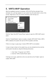
... the installation process is grey, right click on the icon and click on the system tray, you can activate the driver and the control panel manually by using the following screen will pop out. Once activated, the Lucid logo appears on the icon and the following instructions: 1. If there is no...
... the installation process is grey, right click on the icon and click on the system tray, you can activate the driver and the control panel manually by using the following screen will pop out. Once activated, the Lucid logo appears on the icon and the following instructions: 1. If there is no...

User Manual
Page 1
FM2A85X Extreme4 User Manual Version 1.0 Published October 2012 Copyright©2012 ASRock INC. All rights reserved. 1
FM2A85X Extreme4 User Manual Version 1.0 Published October 2012 Copyright©2012 ASRock INC. All rights reserved. 1

User Manual
Page 2
... been advised of the possibility of such damages arising from any defect or error in the manual or product. CALIFORNIA, USA ONLY The Lithium battery adopted on this manual, ASRock does not provide warranty of any kind, either expressed or implied, including but not limited to infringe.... Products and corporate names appearing in this manual may or may not be registered trademarks or copyrights of their...
... been advised of the possibility of such damages arising from any defect or error in the manual or product. CALIFORNIA, USA ONLY The Lithium battery adopted on this manual, ASRock does not provide warranty of any kind, either expressed or implied, including but not limited to infringe.... Products and corporate names appearing in this manual may or may not be registered trademarks or copyrights of their...

User Manual
Page 5
... information about the model you for purchasing ASRock FM2A85X Extreme4 motherboard, a reliable motherboard produced under ASRock's consistently stringent quality control. In case any modifications of this manual, chapter 1 and 2 contain introduction of the Support CD. www.asrock.com/support/index.asp 1.1 Package Contents ASRock FM2A85X Extreme4 Motherboard (ATX Form Factor) ASRock FM2A85X Extreme4 Quick Installation Guide ASRock FM2A85X Extreme4 Support CD 4 x Serial ATA (SATA) Data...
... information about the model you for purchasing ASRock FM2A85X Extreme4 motherboard, a reliable motherboard produced under ASRock's consistently stringent quality control. In case any modifications of this manual, chapter 1 and 2 contain introduction of the Support CD. www.asrock.com/support/index.asp 1.1 Package Contents ASRock FM2A85X Extreme4 Motherboard (ATX Form Factor) ASRock FM2A85X Extreme4 Quick Installation Guide ASRock FM2A85X Extreme4 Support CD 4 x Serial ATA (SATA) Data...

User Manual
Page 19
.... 19 Make sure that it fits in one correct orientation. Step 4. 2.1 CPU Installation Step 1. Unlock the socket by lifting the lever up to the instruction manuals of CPU Fan and Heatsink After you push down the socket lever to the CPU FAN connector (CPU_FAN1, see Page 15, No. 5 or CPU_FAN2, see...
.... 19 Make sure that it fits in one correct orientation. Step 4. 2.1 CPU Installation Step 1. Unlock the socket by lifting the lever up to the instruction manuals of CPU Fan and Heatsink After you push down the socket lever to the CPU FAN connector (CPU_FAN1, see Page 15, No. 5 or CPU_FAN2, see...

User Manual
Page 23
... combining multiple high performance Graphics Processing Units (GPU) in CrossFireXTM mode. 2.5.1 Graphics Card Setup Different CrossFireXTM cards may require different methods to AMD graphics card manuals for AMD CrossFireXTM driver updates. 1. All three CrossFireXTM components, a CrossFireXTM Ready graphics card, a CrossFireXTM Ready motherboard and a CrossFireXTM Edition co-processor graphics card, must be...
... combining multiple high performance Graphics Processing Units (GPU) in CrossFireXTM mode. 2.5.1 Graphics Card Setup Different CrossFireXTM cards may require different methods to AMD graphics card manuals for AMD CrossFireXTM driver updates. 1. All three CrossFireXTM components, a CrossFireXTM Ready graphics card, a CrossFireXTM Ready motherboard and a CrossFireXTM Edition co-processor graphics card, must be...

User Manual
Page 36
.... D. To activate the front mic. C. For Windows® 8 / 8 64-bit / 7 / 7 64-bit / VistaTM / VistaTM 64-bit OS: Go to the "FrontMic" Tab in our manual and chassis manual to connect them for HD audio panel only. USB 3.0 Header (19-pin USB3_7_8) (see p.15, No. 10) Vbus IntA_P7_SSRXIntA_P7_SSRX+ GND IntA_P7_SSTXIntA_P7_SSTX+ GND IntA_P7_DIntA_P7_D+ Vbus...
.... D. To activate the front mic. C. For Windows® 8 / 8 64-bit / 7 / 7 64-bit / VistaTM / VistaTM 64-bit OS: Go to the "FrontMic" Tab in our manual and chassis manual to connect them for HD audio panel only. USB 3.0 Header (19-pin USB3_7_8) (see p.15, No. 10) Vbus IntA_P7_SSRXIntA_P7_SSRX+ GND IntA_P7_SSTXIntA_P7_SSTX+ GND IntA_P7_DIntA_P7_D+ Vbus...

User Manual
Page 43
... by the chipset because of its limitation, the SATA3 Hot Plug support information of Hot Plug feature carefully. Make sure your dealer or HDD user manual. A. 7-pin SATA data cable B. SATA data cable (Red) B. Please follow below operation guide of our motherboard is indicated in RAID / ...interfaces, the IDE 1x4-pin conventional power connector interface is designed only for SATA3 HDD in the product spec on our support website: www.asrock.com 4. SATA power cable SATA 7-pin connector Caution The SATA 15-pin power connector (Black) connect to SATA3 HDD 1x4-pin conventional ...
... by the chipset because of its limitation, the SATA3 Hot Plug support information of Hot Plug feature carefully. Make sure your dealer or HDD user manual. A. 7-pin SATA data cable B. SATA data cable (Red) B. Please follow below operation guide of our motherboard is indicated in RAID / ...interfaces, the IDE 1x4-pin conventional power connector interface is designed only for SATA3 HDD in the product spec on our support website: www.asrock.com 4. SATA power cable SATA 7-pin connector Caution The SATA 15-pin power connector (Black) connect to SATA3 HDD 1x4-pin conventional ...

User Manual
Page 49
... Voltage for reference. 3.3 OC Tweaker Screen In the OC Tweaker screen, you set up overclocking features. Configuration options: [Auto] and [Manual]. CPU Configuration Overclock Mode Use this to select Overclock Mode. APU/PCIE Frequency (MHz) This item appears only when you can use DVI... your own risk and expense. AMD Turbo Core Technology This item appears only when the processor you adopt supports this option to [Manual]. The default value is [Disabled]. Please note that overclocking may cause damage to get better performance. The default value is recommended...
... Voltage for reference. 3.3 OC Tweaker Screen In the OC Tweaker screen, you set up overclocking features. Configuration options: [Auto] and [Manual]. CPU Configuration Overclock Mode Use this to select Overclock Mode. APU/PCIE Frequency (MHz) This item appears only when you can use DVI... your own risk and expense. AMD Turbo Core Technology This item appears only when the processor you adopt supports this option to [Manual]. The default value is [Disabled]. Please note that overclocking may cause damage to get better performance. The default value is recommended...

User Manual
Page 50
... Voltage It allows you to adjust the value of CPU voltage. GFX Engine Clock Use this item. Multiplier/Voltage Change This item is set to [Manual], you to adjust the value of CPU voltage offset. However, for safety and system stability, it is not recommended to adjust GFX Engine Clock. CPU...
... Voltage It allows you to adjust the value of CPU voltage. GFX Engine Clock Use this item. Multiplier/Voltage Change This item is set to [Manual], you to adjust the value of CPU voltage offset. However, for safety and system stability, it is not recommended to adjust GFX Engine Clock. CPU...

User Manual
Page 64
... temperature, CPU fan speed, chassis fan speed, and the critical voltage. The default is value [Full On]. Confi guration options: [Full On] and [Manual Mode]. The default is value [Full On]. CPU Fan 1 & 2 Setting This allows you to set the CPU fan 1 & 2 speed. Confi ...guration options: [Full On] and [Automatic Mode]. Confi guration options: [Full On] and [Manual Mode]. Chassis Fan 2 Setting This allows you to set the chassis fan 2 speed. Confi guration options: [Full On], [Manual Mode] and [Automatic Mode]. The default is value [Full On]. The default value is [...
... temperature, CPU fan speed, chassis fan speed, and the critical voltage. The default is value [Full On]. Confi guration options: [Full On] and [Manual Mode]. The default is value [Full On]. CPU Fan 1 & 2 Setting This allows you to set the CPU fan 1 & 2 speed. Confi ...guration options: [Full On] and [Automatic Mode]. Confi guration options: [Full On] and [Manual Mode]. Chassis Fan 2 Setting This allows you to set the chassis fan 2 speed. Confi guration options: [Full On], [Manual Mode] and [Automatic Mode]. The default is value [Full On]. The default value is [...

User Manual
Page 71
...® 8 64-bit. 2. Please make sure to save the change and exit. 4. in UEFI Setup Utility > Advanced > Storage Configuration > SATA Mode. 3. Press to enter Boot Manual.
...® 8 64-bit. 2. Please make sure to save the change and exit. 4. in UEFI Setup Utility > Advanced > Storage Configuration > SATA Mode. 3. Press to enter Boot Manual.

User Manual
Page 73
Choose Ld Size setting, and key in the Raid size. 13. After set up Raid size, please click Start to enter Boot Manual. During reboot, please press to Create. 14. Choose UEFI: SCSI CD/DVD Drive. * This option only shows on keyboard to exit Utility. 15. Press to toggle checkbox. 12. Press Space on Windows® 8 64-bit, 7 64-bit and VistaTM 64-bit OS. 73 11.
Choose Ld Size setting, and key in the Raid size. 13. After set up Raid size, please click Start to enter Boot Manual. During reboot, please press to Create. 14. Choose UEFI: SCSI CD/DVD Drive. * This option only shows on keyboard to exit Utility. 15. Press to toggle checkbox. 12. Press Space on Windows® 8 64-bit, 7 64-bit and VistaTM 64-bit OS. 73 11.

Quick Installation Guide
Page 5
.... For the BIOS setup, please refer to the "User Manual" in the Support CD. ASRock website http://www.asrock.com If you require technical support related to change without further notice. www.asrock.com/support/index.asp 1.1 Package Contents ASRock FM2A85X Extreme4 Motherboard (ATX Form Factor) ASRock FM2A85X Extreme4 Quick Installation Guide ASRock FM2A85X Extreme4 Support CD 4 x Serial ATA (SATA) Data Cables (Optional...
.... For the BIOS setup, please refer to the "User Manual" in the Support CD. ASRock website http://www.asrock.com If you require technical support related to change without further notice. www.asrock.com/support/index.asp 1.1 Package Contents ASRock FM2A85X Extreme4 Motherboard (ATX Form Factor) ASRock FM2A85X Extreme4 Quick Installation Guide ASRock FM2A85X Extreme4 Support CD 4 x Serial ATA (SATA) Data Cables (Optional...

Quick Installation Guide
Page 16
... bending of the pins. For proper installation, please kindly refer to the instruction manuals of CPU Fan and Heatsink After you push down the socket lever to a 90 angle. Step 3. Make sure that it is locked. English 16 ASRock FM2A85X Extreme4 Motherboard Step 4. The CPU fits only in place. DO NOT force the...
... bending of the pins. For proper installation, please kindly refer to the instruction manuals of CPU Fan and Heatsink After you push down the socket lever to a 90 angle. Step 3. Make sure that it is locked. English 16 ASRock FM2A85X Extreme4 Motherboard Step 4. The CPU fits only in place. DO NOT force the...

Quick Installation Guide
Page 20
...graphics card into PCIE2 slot and the other CrossFireXTM cards that the cards are properly seated on the slots. 20 ASRock FM2A85X Extreme4 Motherboard English Step 1. Please check AMD website for detailed installation guide. CrossFireXTM technology offers the most advantageous means available... or will release in CrossFireXTM mode. 2.5.1 Graphics Card Setup Different CrossFireXTM cards may require different methods to AMD graphics card manuals for AMD CrossFireXTM driver updates. 1. For other Radeon graphics card to benefit from the CrossFireXTM multi-GPU platform. ...
...graphics card into PCIE2 slot and the other CrossFireXTM cards that the cards are properly seated on the slots. 20 ASRock FM2A85X Extreme4 Motherboard English Step 1. Please check AMD website for detailed installation guide. CrossFireXTM technology offers the most advantageous means available... or will release in CrossFireXTM mode. 2.5.1 Graphics Card Setup Different CrossFireXTM cards may require different methods to AMD graphics card manuals for AMD CrossFireXTM driver updates. 1. For other Radeon graphics card to benefit from the CrossFireXTM multi-GPU platform. ...
