
RAID Installation Guide
Page 2
... "User Manual" in the other drive if one drive to the entire system since it will double the data transfer rate of data from one drive fails. 2 Although RAID 0 function can start to use the onboard RAID Option ROM Utility to configure RAID. 1.1 Introduction to RAID The term "RAID" stands for you to RAID mode by following the detailed instruction of the same model and capacity when creating a RAID set the option to configure RAID functions...
... "User Manual" in the other drive if one drive to the entire system since it will double the data transfer rate of data from one drive fails. 2 Although RAID 0 function can start to use the onboard RAID Option ROM Utility to configure RAID. 1.1 Introduction to RAID The term "RAID" stands for you to RAID mode by following the detailed instruction of the same model and capacity when creating a RAID set the option to configure RAID functions...

RAID Installation Guide
Page 8
... the file into one of the USB port. B. Please install the DVD-ROM. Plug a USB drive into your USB flash drive. 8 E. Go to finish the configuration. STEP 3.1: Copy RAID driver to a USB flash drive You can choose either STEP 3.1 or STEP 3.2 to Tools Easy RAID Installer F. During system boot, press or key to find the driver inside your USB flash disk. D. Please download the "SATA Floppy Imaged driver" from ASRock's website A. Insert the Support CD into the DVD-ROM drive. STEP 4: Windows installation A. B. C. During Windows installation process, when Disk...
... the file into one of the USB port. B. Please install the DVD-ROM. Plug a USB drive into your USB flash drive. 8 E. Go to finish the configuration. STEP 3.1: Copy RAID driver to a USB flash drive You can choose either STEP 3.1 or STEP 3.2 to Tools Easy RAID Installer F. During system boot, press or key to find the driver inside your USB flash disk. D. Please download the "SATA Floppy Imaged driver" from ASRock's website A. Insert the Support CD into the DVD-ROM drive. STEP 4: Windows installation A. B. C. During Windows installation process, when Disk...

RAID Installation Guide
Page 12
... Array. *Be sure to finish the configuration. B. Please install the DVD-ROM. STEP 2.2: Download driver from ASRock's website and unzip the file into your USB flash disk. 12 Click to save to finish the driver copy process. Follow instructions to exit. G. A. Go to enter UEFI setup utility. D. Please download the "SATA Floppy Imaged driver" from ASRock's website A. H. During system boot, press or key to Tools Easy RAID Installer F. Insert the Support CD into one of the USB port.
... Array. *Be sure to finish the configuration. B. Please install the DVD-ROM. STEP 2.2: Download driver from ASRock's website and unzip the file into your USB flash disk. 12 Click to save to finish the driver copy process. Follow instructions to exit. G. A. Go to enter UEFI setup utility. D. Please download the "SATA Floppy Imaged driver" from ASRock's website A. H. During system boot, press or key to Tools Easy RAID Installer F. Insert the Support CD into one of the USB port.

Quick Installation Guide
Page 4
... DDR4_B1) 5 2 x 288-pin DDR4 DIMM Slots (DDR4_A2, DDR4_B2) 6 AMD Fan LED Header (AMD_FAN_LED1) 7 ATX Power Connector (ATXPWR1) 8 USB 3.1 Gen1 Header (USB3_56) 9 SATA3 Connector (SATA3_3) 10 SATA3 Connector (SATA3_4) 11 SATA3 Connector (SATA3_2) 12 SATA3 Connector (SATA3_1) 13 System Panel Header (PANEL1) 14 Power LED and Speaker Header (SPK_PLED1) 15 Chassis Intrusion Header (CI1) 16 Chassis/Water Pump Fan Connector (CHA_FAN2/WP) 17 Chassis/Water Pump Fan Connector (CHA_FAN3/WP) 18 Clear CMOS Jumper (CLRCMOS1) 19 USB 2.0 Header (USB_5_6) 20 USB 2.0 Header (USB_3_4) 21 COM Port Header (COM1) 22...
... DDR4_B1) 5 2 x 288-pin DDR4 DIMM Slots (DDR4_A2, DDR4_B2) 6 AMD Fan LED Header (AMD_FAN_LED1) 7 ATX Power Connector (ATXPWR1) 8 USB 3.1 Gen1 Header (USB3_56) 9 SATA3 Connector (SATA3_3) 10 SATA3 Connector (SATA3_4) 11 SATA3 Connector (SATA3_2) 12 SATA3 Connector (SATA3_1) 13 System Panel Header (PANEL1) 14 Power LED and Speaker Header (SPK_PLED1) 15 Chassis Intrusion Header (CI1) 16 Chassis/Water Pump Fan Connector (CHA_FAN2/WP) 17 Chassis/Water Pump Fan Connector (CHA_FAN3/WP) 18 Clear CMOS Jumper (CLRCMOS1) 19 USB 2.0 Header (USB_5_6) 20 USB 2.0 Header (USB_3_4) 21 COM Port Header (COM1) 22...
Quick Installation Guide
Page 7
... will be subject to change without further notice. ASRock website http://www.asrock.com. 1.1 Package Contents • ASRock B450M Pro4 Motherboard (Micro ATX Form Factor) • ASRock B450M Pro4 Quick Installation Guide • ASRock B450M Pro4 Support CD • 1 x I/O Panel Shield • 2 x Serial ATA (SATA) Data Cables (Optional) • 2 x Screws for purchasing ASRock B450M Pro4 motherboard, a reliable motherboard produced under ASRock's consistently stringent quality control. Because the motherboard specifications and the BIOS software might be updated, the content of this...
... will be subject to change without further notice. ASRock website http://www.asrock.com. 1.1 Package Contents • ASRock B450M Pro4 Motherboard (Micro ATX Form Factor) • ASRock B450M Pro4 Quick Installation Guide • ASRock B450M Pro4 Support CD • 1 x I/O Panel Shield • 2 x Serial ATA (SATA) Data Cables (Optional) • 2 x Screws for purchasing ASRock B450M Pro4 motherboard, a reliable motherboard produced under ASRock's consistently stringent quality control. Because the motherboard specifications and the BIOS software might be updated, the content of this...

Quick Installation Guide
Page 9
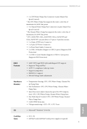
... HBR (High Bit Rate Audio) with HDMI Port (Compliant HDMI monitor is required) • Supports HDCP with DVI-D and HDMI Ports • Supports 4K Ultra HD (UHD) playback with HDMI Port • 7.1 CH HD Audio with Content Protection (Realtek ALC892 Audio Codec) * To configure 7.1 CH HD Audio, it is required to 4K x 2K (4096x2160) @ 24Hz / (3840x2160) @ 30Hz • Supports DVI-D with max. B450M Pro4 Graphics Audio LAN * Supports NVMe SSD as boot disks • 1 x PCI Express 2.0 x1 Slot • Supports AMD Quad...
... HBR (High Bit Rate Audio) with HDMI Port (Compliant HDMI monitor is required) • Supports HDCP with DVI-D and HDMI Ports • Supports 4K Ultra HD (UHD) playback with HDMI Port • 7.1 CH HD Audio with Content Protection (Realtek ALC892 Audio Codec) * To configure 7.1 CH HD Audio, it is required to 4K x 2K (4096x2160) @ 24Hz / (3840x2160) @ 30Hz • Supports DVI-D with max. B450M Pro4 Graphics Audio LAN * Supports NVMe SSD as boot disks • 1 x PCI Express 2.0 x1 Slot • Supports AMD Quad...
Quick Installation Guide
Page 11
...fan is in use. • 1 x 24 pin ATX Power Connector • 1 x 8 pin 12V Power Connector • 1 x Front Panel Audio Connector • 2 x USB 2.0 Headers (Support 4 USB 2.0 ports) (Supports ESD Protection) • 1 x USB 3.1 Gen1 Header (Supports 2 USB 3.1 Gen1 ports) (Supports ESD Protection) BIOS Feature • AMI UEFI Legal BIOS with multilingual GUI support • Supports "Plug and Play" • ACPI 5.1 compliance wake up events • Supports jumperfree • SMBIOS 2.3 support • DRAM Voltage multi-adjustment Hardware Monitor • Temperature Sensing: CPU, CPU...
...fan is in use. • 1 x 24 pin ATX Power Connector • 1 x 8 pin 12V Power Connector • 1 x Front Panel Audio Connector • 2 x USB 2.0 Headers (Support 4 USB 2.0 ports) (Supports ESD Protection) • 1 x USB 3.1 Gen1 Header (Supports 2 USB 3.1 Gen1 ports) (Supports ESD Protection) BIOS Feature • AMI UEFI Legal BIOS with multilingual GUI support • Supports "Plug and Play" • ACPI 5.1 compliance wake up events • Supports jumperfree • SMBIOS 2.3 support • DRAM Voltage multi-adjustment Hardware Monitor • Temperature Sensing: CPU, CPU...

Quick Installation Guide
Page 28
... update the BIOS. However, please do the clear-CMOS action. English 26 Please adjust the BIOS option "Clear Status" to clear the data in CMOS. When the jumper cap is placed on the pins, the jumper is removed. Clear CMOS Jumper (CLRCMOS1) (see p.1, No. 18) 2-pin Jumper Short: Clear CMOS Open: Default CLRCMOS1 allows you clear the CMOS, the case open may be cleared only if the CMOS battery is "Open". To clear and reset the system parameters to default setup, please turn...
... update the BIOS. However, please do the clear-CMOS action. English 26 Please adjust the BIOS option "Clear Status" to clear the data in CMOS. When the jumper cap is placed on the pins, the jumper is removed. Clear CMOS Jumper (CLRCMOS1) (see p.1, No. 18) 2-pin Jumper Short: Clear CMOS Open: Default CLRCMOS1 allows you clear the CMOS, the case open may be cleared only if the CMOS battery is "Open". To clear and reset the system parameters to default setup, please turn...

Quick Installation Guide
Page 30
...+ Dummy 1 There is for internal storage devices with up to this motherboard. Each USB 2.0 header can support two ports. USB 3.1 Gen1 Header (19-pin USB3_56) (see p.1, No. 25) GND PRESENCE# MIC_RET OUT_RET 1 OUT2_L J_SENSE OUT2_R MIC2_R MIC2_L This header is one will be disabled. These four SATA3 connectors support SATA data cables for connecting audio devices to the front audio panel. English 28 Power LED and Speaker Header (7-pin SPK_PLED1) (see p.1, No. 14) Serial ATA3 Connectors (SATA3_1: see p.1, No...
...+ Dummy 1 There is for internal storage devices with up to this motherboard. Each USB 2.0 header can support two ports. USB 3.1 Gen1 Header (19-pin USB3_56) (see p.1, No. 25) GND PRESENCE# MIC_RET OUT_RET 1 OUT2_L J_SENSE OUT2_R MIC2_R MIC2_L This header is one will be disabled. These four SATA3 connectors support SATA data cables for connecting audio devices to the front audio panel. English 28 Power LED and Speaker Header (7-pin SPK_PLED1) (see p.1, No. 14) Serial ATA3 Connectors (SATA3_1: see p.1, No...

User Manual
Page 4
...Contents 1 1.2 Specifications 2 1.3 Motherboard Layout 7 1.4 I/O Panel 9 Chapter 2 Installation 11 2.1 Installing the CPU 12 2.2 Installing the CPU Fan and Heatsink 14 2.3 Installing Memory Modules (DIMM) 22 2.4 Expansion Slots (PCI Express Slots) 25 2.5 Jumpers Setup 26 2.6 Onboard Headers and Connectors 27 2.7 CrossFireXTM and Quad CrossFireXTM Operation Guide 32 2.7.1 Installing Two CrossFireXTM-Ready Graphics Cards 32 2.7.2 Driver Installation and Setup 34 2.8 M.2_SSD (NGFF) Module Installation Guide (M2_1) 35 2.9 M.2_SSD (NGFF) Module Installation Guide (M2_2...
...Contents 1 1.2 Specifications 2 1.3 Motherboard Layout 7 1.4 I/O Panel 9 Chapter 2 Installation 11 2.1 Installing the CPU 12 2.2 Installing the CPU Fan and Heatsink 14 2.3 Installing Memory Modules (DIMM) 22 2.4 Expansion Slots (PCI Express Slots) 25 2.5 Jumpers Setup 26 2.6 Onboard Headers and Connectors 27 2.7 CrossFireXTM and Quad CrossFireXTM Operation Guide 32 2.7.1 Installing Two CrossFireXTM-Ready Graphics Cards 32 2.7.2 Driver Installation and Setup 34 2.8 M.2_SSD (NGFF) Module Installation Guide (M2_1) 35 2.9 M.2_SSD (NGFF) Module Installation Guide (M2_2...
User Manual
Page 7
... are using. ASRock website http://www.asrock.com. 1.1 Package Contents • ASRock B450M Pro4 Motherboard (Micro ATX Form Factor) • ASRock B450M Pro4 Quick Installation Guide • ASRock B450M Pro4 Support CD • 1 x I/O Panel Shield • 2 x Serial ATA (SATA) Data Cables (Optional) • 2 x Screws for purchasing ASRock B450M Pro4 motherboard, a reliable motherboard produced under ASRock's consistently stringent quality control. Because the motherboard specifications and the BIOS software might be updated, the content of this manual will be subject to change...
... are using. ASRock website http://www.asrock.com. 1.1 Package Contents • ASRock B450M Pro4 Motherboard (Micro ATX Form Factor) • ASRock B450M Pro4 Quick Installation Guide • ASRock B450M Pro4 Support CD • 1 x I/O Panel Shield • 2 x Serial ATA (SATA) Data Cables (Optional) • 2 x Screws for purchasing ASRock B450M Pro4 motherboard, a reliable motherboard produced under ASRock's consistently stringent quality control. Because the motherboard specifications and the BIOS software might be updated, the content of this manual will be subject to change...
User Manual
Page 11
...fan is in use. • 1 x 24 pin ATX Power Connector • 1 x 8 pin 12V Power Connector • 1 x Front Panel Audio Connector • 2 x USB 2.0 Headers (Support 4 USB 2.0 ports) (Supports ESD Protection) • 1 x USB 3.1 Gen1 Header (Supports 2 USB 3.1 Gen1 ports) (Supports ESD Protection) BIOS Feature • AMI UEFI Legal BIOS with multilingual GUI support • Supports "Plug and Play" • ACPI 5.1 compliance wake up events • Supports jumperfree • SMBIOS 2.3 support • DRAM Voltage multi-adjustment Hardware Monitor • Temperature Sensing: CPU, CPU...
...fan is in use. • 1 x 24 pin ATX Power Connector • 1 x 8 pin 12V Power Connector • 1 x Front Panel Audio Connector • 2 x USB 2.0 Headers (Support 4 USB 2.0 ports) (Supports ESD Protection) • 1 x USB 3.1 Gen1 Header (Supports 2 USB 3.1 Gen1 ports) (Supports ESD Protection) BIOS Feature • AMI UEFI Legal BIOS with multilingual GUI support • Supports "Plug and Play" • ACPI 5.1 compliance wake up events • Supports jumperfree • SMBIOS 2.3 support • DRAM Voltage multi-adjustment Hardware Monitor • Temperature Sensing: CPU, CPU...

User Manual
Page 32
... pins, the jumper is "Short". However, please do the clear-CMOS action. Please adjust the BIOS option "Clear Status" to default setup, please turn off the computer and unplug the power cord from the power supply. When the jumper cap is placed on the pins, the jumper is removed. To clear and reset the system parameters to clear the record of previous chassis intrusion status. If you update the BIOS. If you need to clear...
... pins, the jumper is "Short". However, please do the clear-CMOS action. Please adjust the BIOS option "Clear Status" to default setup, please turn off the computer and unplug the power cord from the power supply. When the jumper cap is placed on the pins, the jumper is removed. To clear and reset the system parameters to clear the record of previous chassis intrusion status. If you update the BIOS. If you need to clear...

User Manual
Page 34
... connect the chassis power LED and the chassis speaker to this motherboard. Each USB 2.0 header can support two ports. Power LED and Speaker Header (7-pin SPK_PLED1) (see p.7, No. 14) Serial ATA3 Connectors (SATA3_1: see p.7, No. 12) (SATA3_2: see p.7, No. 11) (SATA3_3: see p.7, No. 9) (SATA3_4: see p.7, No. 10) USB 2.0 Headers (9-pin USB_3_4) (see p.7, No. 20) (9-pin USB_5_6) (see p.7, No. 25) GND PRESENCE# MIC_RET OUT_RET 1 OUT2_L J_SENSE OUT2_R MIC2_R MIC2_L This header is for internal storage devices with...
... connect the chassis power LED and the chassis speaker to this motherboard. Each USB 2.0 header can support two ports. Power LED and Speaker Header (7-pin SPK_PLED1) (see p.7, No. 14) Serial ATA3 Connectors (SATA3_1: see p.7, No. 12) (SATA3_2: see p.7, No. 11) (SATA3_3: see p.7, No. 9) (SATA3_4: see p.7, No. 10) USB 2.0 Headers (9-pin USB_3_4) (see p.7, No. 20) (9-pin USB_5_6) (see p.7, No. 25) GND PRESENCE# MIC_RET OUT_RET 1 OUT2_L J_SENSE OUT2_R MIC2_R MIC2_L This header is for internal storage devices with...

User Manual
Page 38
... graphics card driver supports AMD CrossFireXTM technology. Make sure that your system requires. If you pair a 12-pipe CrossFireXTM Edition card with this motherboard. Different CrossFireXTM cards may require different methods to PCIE3 slot. You should only use a AMD certified PSU. It is recommended to the AMD's website for details.) English 32 Please refer to two identical PCI Express x16 graphics cards. 1. Please refer to AMD graphics card manuals for detailed installation guide. 2.7.1 Installing...
... graphics card driver supports AMD CrossFireXTM technology. Make sure that your system requires. If you pair a 12-pipe CrossFireXTM Edition card with this motherboard. Different CrossFireXTM cards may require different methods to PCIE3 slot. You should only use a AMD certified PSU. It is recommended to the AMD's website for details.) English 32 Please refer to two identical PCI Express x16 graphics cards. 1. Please refer to AMD graphics card manuals for detailed installation guide. 2.7.1 Installing...
User Manual
Page 40
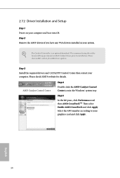
... to installation. Please check AMD's website for AMD driver updates. Please check AMD's website for details. 2.7.2 Driver Installation and Setup Step 1 Power on your graphics card and click Apply. Then select Enable AMD CrossFireX and click Apply. Step 2 Remove the AMD drivers if you have any previously installed Catalyst drivers prior to your computer and boot into OS. We recommend using this utility to uninstall any VGA drivers installed in the Windows® system tray. AMD Catalyst Control...
... to installation. Please check AMD's website for AMD driver updates. Please check AMD's website for details. 2.7.2 Driver Installation and Setup Step 1 Power on your graphics card and click Apply. Then select Enable AMD CrossFireX and click Apply. Step 2 Remove the AMD drivers if you have any previously installed Catalyst drivers prior to your computer and boot into OS. We recommend using this utility to uninstall any VGA drivers installed in the Windows® system tray. AMD Catalyst Control...
User Manual
Page 47
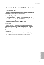
... enhance the motherboard's features. Click on the support CD driver page. Drivers Menu The drivers compatible to your system will be auto-detected and listed on a specific item then follow the order from top to bottom to display the menu. If the Main Menu does not appear automatically, locate and double click on the file "ASRSETUP.EXE" in your CD-ROM drive. Therefore, the drivers you install can work properly. Running...
... enhance the motherboard's features. Click on the support CD driver page. Drivers Menu The drivers compatible to your system will be auto-detected and listed on a specific item then follow the order from top to bottom to display the menu. If the Main Menu does not appear automatically, locate and double click on the file "ASRSETUP.EXE" in your CD-ROM drive. Therefore, the drivers you install can work properly. Running...

User Manual
Page 74
... - 16 cores/3.8GHz on error Controls DF::PIEConfig[DisImmSyncFloodOnFatalError] Disabling this field are from 0x1 (1) - 0x10 (16). The valid values for future selections to scrub memory. DF Common Options DRAM scrub time Provide a value that is required in order for this option sets DF:PIEConfig[DisImmSyncFloodOnFatalError]. 68 English Opcache Control Enables or disables the Opcache. Once this option has been used to remove any cores, a POWER CYCLE...
... - 16 cores/3.8GHz on error Controls DF::PIEConfig[DisImmSyncFloodOnFatalError] Disabling this field are from 0x1 (1) - 0x10 (16). The valid values for future selections to scrub memory. DF Common Options DRAM scrub time Provide a value that is required in order for this option sets DF:PIEConfig[DisImmSyncFloodOnFatalError]. 68 English Opcache Control Enables or disables the Opcache. Once this option has been used to remove any cores, a POWER CYCLE...
User Manual
Page 82
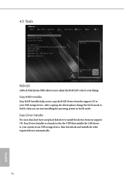
Easy Driver Installer For users that don't have an optical disk drive to install the drivers from the support CD to your USB storage device. Easy RAID Installer Easy RAID Installer helps you can start installing the operating system in the UEFI that installs the LAN driver to your system via an USB storage device, then downloads and installs the other required drivers automatically. 76 English After copying the drivers please change the SATA mode to your liking. 4.5 Tools RGB LED ASRock Polychrome RGB...
Easy Driver Installer For users that don't have an optical disk drive to install the drivers from the support CD to your USB storage device. Easy RAID Installer Easy RAID Installer helps you can start installing the operating system in the UEFI that installs the LAN driver to your system via an USB storage device, then downloads and installs the other required drivers automatically. 76 English After copying the drivers please change the SATA mode to your liking. 4.5 Tools RGB LED ASRock Polychrome RGB...
User Manual
Page 83
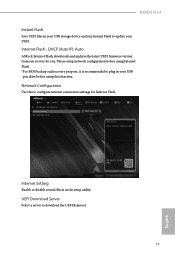
...Setting Enable or disable sound effects in your UEFI. Network Configuration Use this function. UEFI Download Server Select a server to configure internet connection settings for you. B450M Pro4 Instant Flash Save UEFI files in your USB storage device and run Instant Flash to update your USB pen drive before using Internet Flash. *For BIOS backup and recovery purpose, it is recommended to plug in the setup utility. DHCP (Auto IP), Auto ASRock Internet Flash downloads and updates the latest UEFI firmware version from our servers for Internet Flash. Please setup network configuration...
...Setting Enable or disable sound effects in your UEFI. Network Configuration Use this function. UEFI Download Server Select a server to configure internet connection settings for you. B450M Pro4 Instant Flash Save UEFI files in your USB storage device and run Instant Flash to update your USB pen drive before using Internet Flash. *For BIOS backup and recovery purpose, it is recommended to plug in the setup utility. DHCP (Auto IP), Auto ASRock Internet Flash downloads and updates the latest UEFI firmware version from our servers for Internet Flash. Please setup network configuration...


