User Manual
Page 4
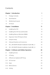
... 9 Chapter 2 Installation 11 2.1 Installing the CPU 12 2.2 Installing the CPU Fan and Heatsink 14 2.3 Installing Memory Modules (DIMM) 23 2.4 Expansion Slots (PCI Express Slots) 26 2.5 Jumpers Setup 27 2.6 Onboard Headers and Connectors 28 2.7 M.2_SSD (NGFF) Module Installation Guide (M2_1) 33 2.8... M.2_SSD (NGFF) Module Installation Guide (M2_2) 36 Chapter 3 Software and Utilities Operation 39 3.1 Installing Drivers 39 3.2 A-Tuning 40 3.3 ASRock Live Update & APP...
... 9 Chapter 2 Installation 11 2.1 Installing the CPU 12 2.2 Installing the CPU Fan and Heatsink 14 2.3 Installing Memory Modules (DIMM) 23 2.4 Expansion Slots (PCI Express Slots) 26 2.5 Jumpers Setup 27 2.6 Onboard Headers and Connectors 28 2.7 M.2_SSD (NGFF) Module Installation Guide (M2_1) 33 2.8... M.2_SSD (NGFF) Module Installation Guide (M2_2) 36 Chapter 3 Software and Utilities Operation 39 3.1 Installing Drivers 39 3.2 A-Tuning 40 3.3 ASRock Live Update & APP...
User Manual
Page 10
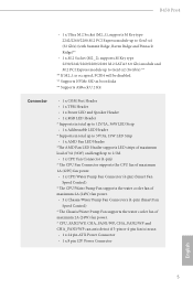
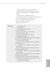
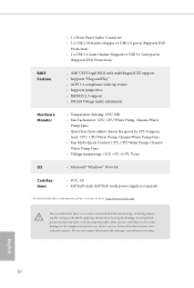
B450 Pro4 • 1 x Ultra M.2 Socket (M2_1), supports M Key type 2242/2260/2280 M.2 PCI Express module up to Gen3 x4 (32 Gb/s) (with Summit Ridge, Raven Ridge and ... boot disks ** Supports ASRock U.2 Kit Connector • 1 x COM Port Header • 1 x TPM Header • 1 x Power LED and Speaker Header • 1 x RGB LED Header * Supports in total up to 12V/3A, 36W LED Strip • 1 x Addressable LED Header * Supports in total up to 5V/3A, 15W LED Strip • 1 x AMD Fan LED Header *The AMD Fan LED Header supports LED strips...
B450 Pro4 • 1 x Ultra M.2 Socket (M2_1), supports M Key type 2242/2260/2280 M.2 PCI Express module up to Gen3 x4 (32 Gb/s) (with Summit Ridge, Raven Ridge and ... boot disks ** Supports ASRock U.2 Kit Connector • 1 x COM Port Header • 1 x TPM Header • 1 x Power LED and Speaker Header • 1 x RGB LED Header * Supports in total up to 12V/3A, 36W LED Strip • 1 x Addressable LED Header * Supports in total up to 5V/3A, 15W LED Strip • 1 x AMD Fan LED Header *The AMD Fan LED Header supports LED strips...
User Manual
Page 11
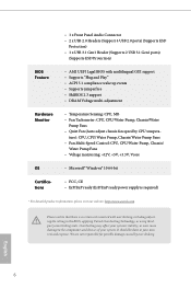
... Protection) • 1 x USB 3.1 Gen1 Header (Supports 2 USB 3.1 Gen1 ports) (Supports ESD Protection) BIOS Feature • AMI UEFI Legal BIOS with overclocking, including adjusting the setting in the BIOS, applying Untied Overclocking Technology, or using thirdparty overclocking tools. ture): CPU, CPU/Water Pump, Chassis/Water Pump Fans • Fan Multi-Speed Control: CPU, CPU...
... Protection) • 1 x USB 3.1 Gen1 Header (Supports 2 USB 3.1 Gen1 ports) (Supports ESD Protection) BIOS Feature • AMI UEFI Legal BIOS with overclocking, including adjusting the setting in the BIOS, applying Untied Overclocking Technology, or using thirdparty overclocking tools. ture): CPU, CPU/Water Pump, Chassis/Water Pump Fans • Fan Multi-Speed Control: CPU, CPU...
User Manual
Page 13
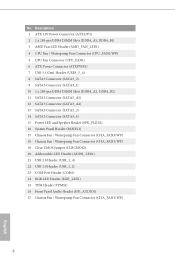
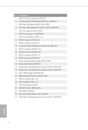
... System Panel Header (PANEL1) 17 Chassis Fan / Waterpump Fan Connector (CHA_FAN3/WP) 18 Chassis Fan / Waterpump Fan Connector (CHA_FAN2/WP) 19 Clear CMOS Jumper (CLRCMOS2) 20 Addressable LED Header (ADDR_LED1) 21 USB 2.0 Header (USB_3_4) 22 USB 2.0 Header (USB_1_2) 23 COM Port Header (COM1) 24 RGB LED Header (RGB_LED1) 25 TPM Header (TPMS1) 26 Front Panel Audio Header (HD_AUDIO1) 27 Chassis Fan / Waterpump Fan Connector...
... System Panel Header (PANEL1) 17 Chassis Fan / Waterpump Fan Connector (CHA_FAN3/WP) 18 Chassis Fan / Waterpump Fan Connector (CHA_FAN2/WP) 19 Clear CMOS Jumper (CLRCMOS2) 20 Addressable LED Header (ADDR_LED1) 21 USB 2.0 Header (USB_3_4) 22 USB 2.0 Header (USB_1_2) 23 COM Port Header (COM1) 24 RGB LED Header (RGB_LED1) 25 TPM Header (TPMS1) 26 Front Panel Audio Header (HD_AUDIO1) 27 Chassis Fan / Waterpump Fan Connector...
User Manual
Page 23
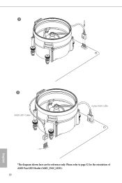
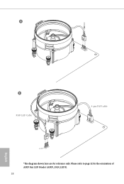
Please refer to page 32 for reference only. 4 CPU_FAN1 5 RGB LED Cable 4-pin FAN cable CPU_FAN1 +12V AMD_FAN_LED1 *The diagram shown here are for the orientation of AMD Fan LED Header (AMD_FAN_LED1). 18 English
Please refer to page 32 for reference only. 4 CPU_FAN1 5 RGB LED Cable 4-pin FAN cable CPU_FAN1 +12V AMD_FAN_LED1 *The diagram shown here are for the orientation of AMD Fan LED Header (AMD_FAN_LED1). 18 English
User Manual
Page 27
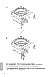
Please refer to page 32 for reference only. If you select USB connector, please install AMD utility "SR3 Settings Software". *The diagram shown here are for the orientation of AMD Fan LED Header (AMD_FAN_LED1). 22 English If you select AMD_FAN_LED1, please install ASRock utility "ASRock Polychrome LED". 6 CPU_FAN1 +12V AMD_FAN_LED1 or 7 CPU_FAN1 AMD_FAN_LED1 USB_5 Please note that only one cable should be used at a time in this step.
Please refer to page 32 for reference only. If you select USB connector, please install AMD utility "SR3 Settings Software". *The diagram shown here are for the orientation of AMD Fan LED Header (AMD_FAN_LED1). 22 English If you select AMD_FAN_LED1, please install ASRock utility "ASRock Polychrome LED". 6 CPU_FAN1 +12V AMD_FAN_LED1 or 7 CPU_FAN1 AMD_FAN_LED1 USB_5 Please note that only one cable should be used at a time in this step.
User Manual
Page 35
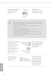
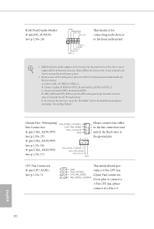
...but the panel wire on the chassis must support HDA to Ground (GND). C. English 30 Front Panel Audio Header (9-pin HD_AUDIO1) (see p.7, No. 5) 3 CPU_FAN_SPEED (Quiet Fan) connector. 4 FAN_SPEED_CONTROL If you use an AC'97 audio panel, please install it to Pin 1-3. Connect ...and OUT_RET are for the HD audio panel only. Chassis Fan / Waterpump Fan Connectors (4-pin CHA_FAN1/WP) FAN_SPEED_CONTROL CHA_FAN_SPEED FAN_VOLTAGE GND Please connect fan cables 4 3 to the fan connectors and 2 1 match the black wire to the front panel audio header by the steps below: A. E. If you plan ...
...but the panel wire on the chassis must support HDA to Ground (GND). C. English 30 Front Panel Audio Header (9-pin HD_AUDIO1) (see p.7, No. 5) 3 CPU_FAN_SPEED (Quiet Fan) connector. 4 FAN_SPEED_CONTROL If you use an AC'97 audio panel, please install it to Pin 1-3. Connect ...and OUT_RET are for the HD audio panel only. Chassis Fan / Waterpump Fan Connectors (4-pin CHA_FAN1/WP) FAN_SPEED_CONTROL CHA_FAN_SPEED FAN_VOLTAGE GND Please connect fan cables 4 3 to the fan connectors and 2 1 match the black wire to the front panel audio header by the steps below: A. E. If you plan ...
User Manual
Page 36
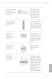
TPM Header (17-pin TPMS1) (see p.7, No. 1) 8 5 This motherboard provides a 8-pin ATX 12V power connector. To use a 4 1 4-pin ATX power supply, please plug it to Pin 1-3. 12... digital identities, and ensures platform integrity. 31 English B450 Pro4 CPU Fan / Waterpump 1 Fan Connector 2 (4-pin CPU_FAN2/WP) 3 4 (see p.7, No. 4) ATX Power Connector (24-pin ATXPWR1) (see p.7, No. 23) RRXD1 DDTR#1 DDSR#1 CCTS#1 1 RRI#1 RRTS#1 GND TTXD1 DDCD#1 This COM1 header supports a serial port module. Serial Port Header (9-pin COM1) (see p.7, No. 6) GND FAN_VOLTAGE This ...
TPM Header (17-pin TPMS1) (see p.7, No. 1) 8 5 This motherboard provides a 8-pin ATX 12V power connector. To use a 4 1 4-pin ATX power supply, please plug it to Pin 1-3. 12... digital identities, and ensures platform integrity. 31 English B450 Pro4 CPU Fan / Waterpump 1 Fan Connector 2 (4-pin CPU_FAN2/WP) 3 4 (see p.7, No. 4) ATX Power Connector (24-pin ATXPWR1) (see p.7, No. 23) RRXD1 DDTR#1 DDSR#1 CCTS#1 1 RRI#1 RRTS#1 GND TTXD1 DDCD#1 This COM1 header supports a serial port module. Serial Port Header (9-pin COM1) (see p.7, No. 6) GND FAN_VOLTAGE This ...
User Manual
Page 37
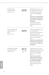
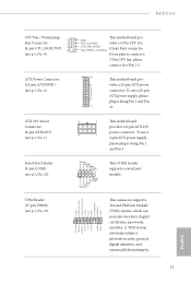
... may be damaged. *Please refer to page 50 for further instructions on this header. AMD FAN LED Header is used to page 49 for further instructions on this header. This header is used to connect Addressable LED extension cable which allows users to choose from various... users to choose from various LED lighting effects. English 32 Caution: Never install the FAN LED cable in the wrong orientation; RGB LED Header (4-pin RGB_LED1) (see p.7, No. 24) AMD FAN LED Header (4-pin AMD_FAN_ LED1) (see p.7, No. 3) Addressable LED Header (3-pin ADDR_LED1) (see p.7, No. 20) 1 12V G R B 1 12V...
... may be damaged. *Please refer to page 50 for further instructions on this header. AMD FAN LED Header is used to page 49 for further instructions on this header. This header is used to connect Addressable LED extension cable which allows users to choose from various... users to choose from various LED lighting effects. English 32 Caution: Never install the FAN LED cable in the wrong orientation; RGB LED Header (4-pin RGB_LED1) (see p.7, No. 24) AMD FAN LED Header (4-pin AMD_FAN_ LED1) (see p.7, No. 3) Addressable LED Header (3-pin ADDR_LED1) (see p.7, No. 20) 1 12V G R B 1 12V...
Quick Installation Guide
Page 4
... System Panel Header (PANEL1) 17 Chassis Fan / Waterpump Fan Connector (CHA_FAN3/WP) 18 Chassis Fan / Waterpump Fan Connector (CHA_FAN2/WP) 19 Clear CMOS Jumper (CLRCMOS2) 20 Addressable LED Header (ADDR_LED1) 21 USB 2.0 Header (USB_3_4) 22 USB 2.0 Header (USB_1_2) 23 COM Port Header (COM1) 24 RGB LED Header (RGB_LED1) 25 TPM Header (TPMS1) 26 Front Panel Audio Header (HD_AUDIO1) 27 Chassis Fan / Waterpump Fan Connector...
... System Panel Header (PANEL1) 17 Chassis Fan / Waterpump Fan Connector (CHA_FAN3/WP) 18 Chassis Fan / Waterpump Fan Connector (CHA_FAN2/WP) 19 Clear CMOS Jumper (CLRCMOS2) 20 Addressable LED Header (ADDR_LED1) 21 USB 2.0 Header (USB_3_4) 22 USB 2.0 Header (USB_1_2) 23 COM Port Header (COM1) 24 RGB LED Header (RGB_LED1) 25 TPM Header (TPMS1) 26 Front Panel Audio Header (HD_AUDIO1) 27 Chassis Fan / Waterpump Fan Connector...
Quick Installation Guide
Page 11
B450 Pro4 • 1 x Ultra M.2 Socket (M2_1), supports M Key type 2242/2260/2280 M.2 PCI Express module up to Gen3 x4 (32 Gb/s) (with Summit Ridge, Raven Ridge and ... boot disks ** Supports ASRock U.2 Kit Connector • 1 x COM Port Header • 1 x TPM Header • 1 x Power LED and Speaker Header • 1 x RGB LED Header * Supports in total up to 12V/3A, 36W LED Strip • 1 x Addressable LED Header * Supports in total up to 5V/3A, 15W LED Strip • 1 x AMD Fan LED Header *The AMD Fan LED Header supports LED strips...
B450 Pro4 • 1 x Ultra M.2 Socket (M2_1), supports M Key type 2242/2260/2280 M.2 PCI Express module up to Gen3 x4 (32 Gb/s) (with Summit Ridge, Raven Ridge and ... boot disks ** Supports ASRock U.2 Kit Connector • 1 x COM Port Header • 1 x TPM Header • 1 x Power LED and Speaker Header • 1 x RGB LED Header * Supports in total up to 12V/3A, 36W LED Strip • 1 x Addressable LED Header * Supports in total up to 5V/3A, 15W LED Strip • 1 x AMD Fan LED Header *The AMD Fan LED Header supports LED strips...
Quick Installation Guide
Page 12
... Pump Fans • Quiet Fan (Auto adjust chassis fan speed by overclocking. We are not responsible for possible damage caused by CPU tempera- Overclocking may affect your system's stability, or even cause damage to the components and devices of your own risk and expense. English 10 • 1 x Front Panel Audio Connector • 2 x USB 2.0 Headers...
... Pump Fans • Quiet Fan (Auto adjust chassis fan speed by overclocking. We are not responsible for possible damage caused by CPU tempera- Overclocking may affect your system's stability, or even cause damage to the components and devices of your own risk and expense. English 10 • 1 x Front Panel Audio Connector • 2 x USB 2.0 Headers...
Quick Installation Guide
Page 20
Please refer to page 32 for reference only. 4 CPU_FAN1 5 RGB LED Cable 4-pin FAN cable CPU_FAN1 +12V AMD_FAN_LED1 *The diagram shown here are for the orientation of AMD Fan LED Header (AMD_FAN_LED1). 18 English
Please refer to page 32 for reference only. 4 CPU_FAN1 5 RGB LED Cable 4-pin FAN cable CPU_FAN1 +12V AMD_FAN_LED1 *The diagram shown here are for the orientation of AMD Fan LED Header (AMD_FAN_LED1). 18 English

Quick Installation Guide
Page 24
If you select AMD_FAN_LED1, please install ASRock utility "ASRock Polychrome LED". If you select USB connector, please install AMD utility "SR3 Settings Software". *The diagram shown here are for the orientation of AMD Fan LED Header (AMD_FAN_LED1). 22 English 6 CPU_FAN1 +12V AMD_FAN_LED1 or 7 CPU_FAN1 AMD_FAN_LED1 USB_5 Please note that only one cable should be used at a time in this step. Please refer to page 32 for reference only.
If you select AMD_FAN_LED1, please install ASRock utility "ASRock Polychrome LED". If you select USB connector, please install AMD utility "SR3 Settings Software". *The diagram shown here are for the orientation of AMD Fan LED Header (AMD_FAN_LED1). 22 English 6 CPU_FAN1 +12V AMD_FAN_LED1 or 7 CPU_FAN1 AMD_FAN_LED1 USB_5 Please note that only one cable should be used at a time in this step. Please refer to page 32 for reference only.
Quick Installation Guide
Page 32
... connect it to Ground (GND). Connect Ground (GND) to the front panel audio header by the steps below: A. To activate the front mic, go to the ground pin. Chassis Fan / Waterpump Fan Connectors (4-pin CHA_FAN1/WP) (see p.1, No. 27) (4-pin CHA_FAN2/WP) (see p.1, No. 18) (4-pin ...CHA_FAN3/WP) (see p.1, No. 17) FAN_SPEED_CONTROL CHA_FAN_SPEED FAN_VOLTAGE GND 43 21 Please connect fan cables 4 3 to the fan connectors and 2 1 match the black wire to the "FrontMic" Tab in our manual and chassis manual to function correctly. English 30 Connect ...
... connect it to Ground (GND). Connect Ground (GND) to the front panel audio header by the steps below: A. To activate the front mic, go to the ground pin. Chassis Fan / Waterpump Fan Connectors (4-pin CHA_FAN1/WP) (see p.1, No. 27) (4-pin CHA_FAN2/WP) (see p.1, No. 18) (4-pin ...CHA_FAN3/WP) (see p.1, No. 17) FAN_SPEED_CONTROL CHA_FAN_SPEED FAN_VOLTAGE GND 43 21 Please connect fan cables 4 3 to the fan connectors and 2 1 match the black wire to the "FrontMic" Tab in our manual and chassis manual to function correctly. English 30 Connect ...
Quick Installation Guide
Page 33
... To use a 4 1 4-pin ATX power supply, please plug it along Pin 1 and Pin 5. Serial Port Header (9-pin COM1) (see p.1, No. 23) TPM Header (17-pin TPMS1) (see p.1, No. 1) 8 5 This motherboard provides a 8-pin ATX 12V power connector. B450 Pro4 CPU Fan / Waterpump 1 Fan Connector 2 (4-pin CPU_FAN2/WP) 3 4 (see p.1, No. 4) ATX Power Connector (24-pin ATXPWR1) (see p.1, No...
... To use a 4 1 4-pin ATX power supply, please plug it along Pin 1 and Pin 5. Serial Port Header (9-pin COM1) (see p.1, No. 23) TPM Header (17-pin TPMS1) (see p.1, No. 1) 8 5 This motherboard provides a 8-pin ATX 12V power connector. B450 Pro4 CPU Fan / Waterpump 1 Fan Connector 2 (4-pin CPU_FAN2/WP) 3 4 (see p.1, No. 4) ATX Power Connector (24-pin ATXPWR1) (see p.1, No...

Quick Installation Guide
Page 34
... otherwise, the cable may be damaged. *Please refer to page 40 for further instructions on this header. otherwise, the cable may be damaged. RGB LED Header (4-pin RGB_LED1) (see p.1, No. 24) AMD FAN LED Header (4-pin AMD_FAN_ LED1) (see p.1, No. 3) Addressable LED Header (3-pin ADDR_LED1) (see p.1, No. 20) 1 12V G R B 1 12V G R B 1 GND DO_ADDR VOUT RGB LED...
... otherwise, the cable may be damaged. *Please refer to page 40 for further instructions on this header. otherwise, the cable may be damaged. RGB LED Header (4-pin RGB_LED1) (see p.1, No. 24) AMD FAN LED Header (4-pin AMD_FAN_ LED1) (see p.1, No. 3) Addressable LED Header (3-pin ADDR_LED1) (see p.1, No. 20) 1 12V G R B 1 12V G R B 1 GND DO_ADDR VOUT RGB LED...


