
User Manual
Page 3
... Guide 18 2.6 Jumpers Setup 19 2.7 Onboard Headers and Connectors 20 2.8 Serial ATA (SATA) / Serial ATA2 (SATA2) Hard Disks Installation 23 2.9 Hot Plug and Hot Swap Functions for SATA / SATA2 HDDs 23 2.10 SATA / SATA2 HDD Hot Plug Feature and Operation Guide 24 2.11 Driver Installation Guide 26 2.12 Installing Windows® 7 on SATA / SATAII HDDs ........ 26 3 UEFI SETUP UTILITY 27 3.1 Introduction 27 3.1.1 UEFI Menu Bar 27 3.1.2 Navigation Keys 28 3.2 Main Screen 28 3.3 Advanced Screen 30 3.3.1 CPU Configuration 31 3.3.2 Chipset Configuration 32 3.3.3 Storage...
... Guide 18 2.6 Jumpers Setup 19 2.7 Onboard Headers and Connectors 20 2.8 Serial ATA (SATA) / Serial ATA2 (SATA2) Hard Disks Installation 23 2.9 Hot Plug and Hot Swap Functions for SATA / SATA2 HDDs 23 2.10 SATA / SATA2 HDD Hot Plug Feature and Operation Guide 24 2.11 Driver Installation Guide 26 2.12 Installing Windows® 7 on SATA / SATAII HDDs ........ 26 3 UEFI SETUP UTILITY 27 3.1 Introduction 27 3.1.1 UEFI Menu Bar 27 3.1.2 Navigation Keys 28 3.2 Main Screen 28 3.3 Advanced Screen 30 3.3.1 CPU Configuration 31 3.3.2 Chipset Configuration 32 3.3.3 Storage...
User Manual
Page 5
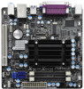
... ASRock AD2700B-ITX / AD2500B-ITX Motherboard (Mini-ITX Form Factor: 6.7-in x 6.7-in, 17.0 cm x 17.0 cm) ASRock AD2700B-ITX / AD2500B-ITX Quick Installation Guide ASRock AD2700B-ITX / AD2500B-ITX Support CD 2 x Serial ATA (SATA) Data Cables (Optional) 1 x I/O Panel Shield 5 Chapter 1: Introduction Thank you for specific information about the model you require technical support related to quality and endurance. In this manual will be subject to the hardware installation. You may find the latest VGA cards and CPU support lists...
... ASRock AD2700B-ITX / AD2500B-ITX Motherboard (Mini-ITX Form Factor: 6.7-in x 6.7-in, 17.0 cm x 17.0 cm) ASRock AD2700B-ITX / AD2500B-ITX Quick Installation Guide ASRock AD2700B-ITX / AD2500B-ITX Support CD 2 x Serial ATA (SATA) Data Cables (Optional) 1 x I/O Panel Shield 5 Chapter 1: Introduction Thank you for specific information about the model you require technical support related to quality and endurance. In this manual will be subject to the hardware installation. You may find the latest VGA cards and CPU support lists...

User Manual
Page 7
... ASM1042, support USB 1.0/2.0/3.0 up to -Use USB 2.0 Ports - 1 x RJ-45 LAN Port with LED (ACT/LINK LED and SPEED LED) - Front panel audio connector - 2 x USB 2.0 headers (support 4 USB 2.0 ports) - 16Mb AMI BIOS - ACPI 1.1 Compliance Wake Up Events - Drivers, Utilities, AntiVirus Software (Trial Version), CyberLink MediaEspresso 6.5 Trial, ASRock Software Suite (CyberLink DVD Suite - ASRock SmartView (see CAUTION 6) - ASRock XFast USB (see CAUTION 5) - ASRock APP Charger (see CAUTION 7) 7 ASRock XFast LAN (see CAUTION 4) - CPU/Chassis FAN connector - 24 pin ATX power connector...
... ASM1042, support USB 1.0/2.0/3.0 up to -Use USB 2.0 Ports - 1 x RJ-45 LAN Port with LED (ACT/LINK LED and SPEED LED) - Front panel audio connector - 2 x USB 2.0 headers (support 4 USB 2.0 ports) - 16Mb AMI BIOS - ACPI 1.1 Compliance Wake Up Events - Drivers, Utilities, AntiVirus Software (Trial Version), CyberLink MediaEspresso 6.5 Trial, ASRock Software Suite (CyberLink DVD Suite - ASRock SmartView (see CAUTION 6) - ASRock XFast USB (see CAUTION 5) - ASRock APP Charger (see CAUTION 7) 7 ASRock XFast LAN (see CAUTION 4) - CPU/Chassis FAN connector - 24 pin ATX power connector...

User Manual
Page 9
... MS-DOS or Windows®. ASRock APP Charger. Simply install the APP Charger driver, it can press the key during the POST or the key to RAM (S3), hibernation mode (S4) or power off (S5). About the setting of charging your PC enters into Standby mode (S1), Suspend to enter into an enhanced view for a more personal Internet experience. Due to access ASRock Instant Flash. The performance...
... MS-DOS or Windows®. ASRock APP Charger. Simply install the APP Charger driver, it can press the key during the POST or the key to RAM (S3), hibernation mode (S4) or power off (S5). About the setting of charging your PC enters into Standby mode (S1), Suspend to enter into an enhanced view for a more personal Internet experience. Due to access ASRock Instant Flash. The performance...

User Manual
Page 20
...) 1 GND IRTX IRRX ATX+5VSB This header can be connected to the SATA / SATA2 hard disk or the SATA2 connector on this motherboard. Consumer Infrared Module Header (4-pin CIR1) (see p.11 or 12 No. 7) Besides the default USB 2.0 ports on the I/O panel, there are NOT jumpers. 2.7 Onboard Headers and Connectors Onboard headers and connectors are two USB 2.0 headers on this motherboard. Serial ATA (SATA) Data Cable (Optional) Either end of the motherboard! Each USB 2.0 header can be used to 3.0 Gb/s data transfer...
...) 1 GND IRTX IRRX ATX+5VSB This header can be connected to the SATA / SATA2 hard disk or the SATA2 connector on this motherboard. Consumer Infrared Module Header (4-pin CIR1) (see p.11 or 12 No. 7) Besides the default USB 2.0 ports on the I/O panel, there are NOT jumpers. 2.7 Onboard Headers and Connectors Onboard headers and connectors are two USB 2.0 headers on this motherboard. Serial ATA (SATA) Data Cable (Optional) Either end of the motherboard! Each USB 2.0 header can be used to 3.0 Gb/s data transfer...

User Manual
Page 22
Please connect the CPU fan cable to the connector and match the black wire to the ground pin. Please connect an ATX power supply to this connector. 1 13 Though this header. Please connect the fan cable to the fan connector and match the black wire to the ground pin. A front panel module mainly consists of power switch, reset switch, power LED, hard drive activity LED, speaker and etc. Chassis Speaker Header (4-pin SPEAKER 1) (see p.11 or 12 No. 12) Chassis Fan Connector (3-pin CHA_FAN1) (see p.11 or 12 No. 3) CPU Fan Connector (3-pin CPU_FAN1) (see p.11...
Please connect the CPU fan cable to the connector and match the black wire to the ground pin. Please connect an ATX power supply to this connector. 1 13 Though this header. Please connect the fan cable to the fan connector and match the black wire to the ground pin. A front panel module mainly consists of power switch, reset switch, power LED, hard drive activity LED, speaker and etc. Chassis Speaker Header (4-pin SPEAKER 1) (see p.11 or 12 No. 12) Chassis Fan Connector (3-pin CHA_FAN1) (see p.11 or 12 No. 3) CPU Fan Connector (3-pin CPU_FAN1) (see p.11...

User Manual
Page 26
.... Storage Configuration. Set the option "SATA Mode" to [AHCI]. A. STEP 2: Install Windows® 7 OS on your SATA / SATAII HDDs, please follow the order from up to bottom side to your system can work properly. 2.12 Installing Windows® 7 on SATA / SATAII HDDs If you install can be auto-detected and listed on your optical drive first. Then, the drivers compatible to install those required drivers. Please follow below steps. Enter UEFI SETUP UTILITY Advanced screen...
.... Storage Configuration. Set the option "SATA Mode" to [AHCI]. A. STEP 2: Install Windows® 7 OS on your SATA / SATAII HDDs, please follow the order from up to bottom side to your system can work properly. 2.12 Installing Windows® 7 on SATA / SATAII HDDs If you install can be auto-detected and listed on your optical drive first. Then, the drivers compatible to install those required drivers. Please follow below steps. Enter UEFI SETUP UTILITY Advanced screen...

User Manual
Page 27
... pressing the reset button on . You can also use the UEFI SETUP UTILITY to click your required item. 27 Because the UEFI software is constantly being updated, the following selections: Main To set up the system time/date information OC Tweaker To set up overclocking features Advanced To set up the advanced UEFI features H/W Monitor To display current hardware status Boot To set up the default system device to locate and load the...
... pressing the reset button on . You can also use the UEFI SETUP UTILITY to click your required item. 27 Because the UEFI software is constantly being updated, the following selections: Main To set up the system time/date information OC Tweaker To set up overclocking features Advanced To set up the advanced UEFI features H/W Monitor To display current hardware status Boot To set up the default system device to locate and load the...

User Manual
Page 32
... to use this motherboard to submit Windows® certification. The default value is selected, the AC/power resumes and the system starts to set this option to enable or disable ACPI HPET Table. Onboard LAN This allows you to boot up when the power recovers. Good Night LED Enable this item to [Enabled] if you select [Auto], the onboard HD Audio will also be disabled when PCI Sound Card is plugged. Please set the power state...
... to use this motherboard to submit Windows® certification. The default value is selected, the AC/power resumes and the system starts to set this option to enable or disable ACPI HPET Table. Onboard LAN This allows you to boot up when the power recovers. Good Night LED Enable this item to [Enabled] if you select [Auto], the onboard HD Audio will also be disabled when PCI Sound Card is plugged. Please set the power state...

User Manual
Page 36
...Controller Use this option to select legacy support for USB devices. Legacy USB Support Use this item to enable or disable the use of USB 2.0 controller. The default value is recommended to select [Disabled] to enter OS. [UEFI Setup Only] - Legacy USB 3.0 Support Use this item to enable or disable the use of these four options: [Enabled] - There are connected. [Disabled] - Please refer to below descriptions for the details of USB 3.0 controller. If you have USB compatibility issue, it is [Enabled]. Enables support for legacy USB. [Auto] - Enables legacy support if USB...
...Controller Use this option to select legacy support for USB devices. Legacy USB Support Use this item to enable or disable the use of USB 2.0 controller. The default value is recommended to select [Disabled] to enter OS. [UEFI Setup Only] - Legacy USB 3.0 Support Use this item to enable or disable the use of these four options: [Enabled] - There are connected. [Disabled] - Please refer to below descriptions for the details of USB 3.0 controller. If you have USB compatibility issue, it is [Enabled]. Enables support for legacy USB. [Auto] - Enables legacy support if USB...
User Manual
Page 42
.... Click on the file "ASSETUP.EXE" from the BIN folder in this chapter for more about ASRock, welcome to display the menus. 4.2.2 Drivers Menu The Drivers Menu shows the available devices drivers if the system detects installed devices. Please install the necessary drivers to your computer. Because motherboard settings and hardware options vary, use the setup procedures in the Support CD to visit ASRock's website at http://www...
.... Click on the file "ASSETUP.EXE" from the BIN folder in this chapter for more about ASRock, welcome to display the menus. 4.2.2 Drivers Menu The Drivers Menu shows the available devices drivers if the system detects installed devices. Please install the necessary drivers to your computer. Because motherboard settings and hardware options vary, use the setup procedures in the Support CD to visit ASRock's website at http://www...
Quick Installation Guide
Page 2
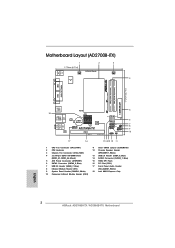
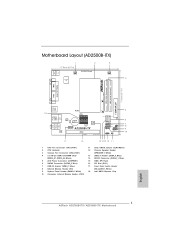
...) 2 CPU Heatsink 3 Chassis Fan Connector (CHA_FAN1) 4 2 x 240-pin DDR3 SO-DIMM Slots (DDR3_A1, DDR3_A2, Black) 5 ATX Power Connector (ATXPWR1) 6 SATA2 Connector (SATAII_2, Blue) 7 USB 2.0 Header (USB6_7, Blue) 8 Infrared Module Header (IR1) 9 System Panel Header (PANEL1, White) 10 Consumer Infrared Module Header (CIR1) 11 Clear CMOS Jumper (CLRCMOS1) 12 Chassis Speaker Header (SPEAKER 1, White) 13 USB 2.0 Header (USB4_5, Blue) 14 SATA2 Connector (SATAII_1, Blue) 15 16Mb SPI Flash 16 PCI Slot (PCI1) 17 Front Panel Audio Header (HD_AUDIO1, White) 18 Intel NM10 Express Chip English 2 ASRock...
...) 2 CPU Heatsink 3 Chassis Fan Connector (CHA_FAN1) 4 2 x 240-pin DDR3 SO-DIMM Slots (DDR3_A1, DDR3_A2, Black) 5 ATX Power Connector (ATXPWR1) 6 SATA2 Connector (SATAII_2, Blue) 7 USB 2.0 Header (USB6_7, Blue) 8 Infrared Module Header (IR1) 9 System Panel Header (PANEL1, White) 10 Consumer Infrared Module Header (CIR1) 11 Clear CMOS Jumper (CLRCMOS1) 12 Chassis Speaker Header (SPEAKER 1, White) 13 USB 2.0 Header (USB4_5, Blue) 14 SATA2 Connector (SATAII_1, Blue) 15 16Mb SPI Flash 16 PCI Slot (PCI1) 17 Front Panel Audio Header (HD_AUDIO1, White) 18 Intel NM10 Express Chip English 2 ASRock...
Quick Installation Guide
Page 3
...) 2 CPU Heatsink 3 Chassis Fan Connector (CHA_FAN1) 4 2 x 240-pin DDR3 SO-DIMM Slots (DDR3_A1, DDR3_A2, Black) 5 ATX Power Connector (ATXPWR1) 6 SATA2 Connector (SATAII_2, Blue) 7 USB 2.0 Header (USB6_7, Blue) 8 Infrared Module Header (IR1) 9 System Panel Header (PANEL1, White) 10 Consumer Infrared Module Header (CIR1) 11 Clear CMOS Jumper (CLRCMOS1) 12 Chassis Speaker Header (SPEAKER 1, White) 13 USB 2.0 Header (USB4_5, Blue) 14 SATA2 Connector (SATAII_1, Blue) 15 16Mb SPI Flash 16 PCI Slot (PCI1) 17 Front Panel Audio Header (HD_AUDIO1, White) 18 Intel NM10 Express Chip English 3 ASRock...
...) 2 CPU Heatsink 3 Chassis Fan Connector (CHA_FAN1) 4 2 x 240-pin DDR3 SO-DIMM Slots (DDR3_A1, DDR3_A2, Black) 5 ATX Power Connector (ATXPWR1) 6 SATA2 Connector (SATAII_2, Blue) 7 USB 2.0 Header (USB6_7, Blue) 8 Infrared Module Header (IR1) 9 System Panel Header (PANEL1, White) 10 Consumer Infrared Module Header (CIR1) 11 Clear CMOS Jumper (CLRCMOS1) 12 Chassis Speaker Header (SPEAKER 1, White) 13 USB 2.0 Header (USB4_5, Blue) 14 SATA2 Connector (SATAII_1, Blue) 15 16Mb SPI Flash 16 PCI Slot (PCI1) 17 Front Panel Audio Header (HD_AUDIO1, White) 18 Intel NM10 Express Chip English 3 ASRock...

Quick Installation Guide
Page 6
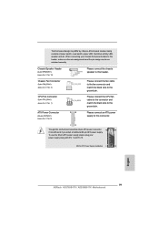
...purchasing ASRock AD2700B-ITX / AD2500B-ITX motherboard, a reliable motherboard produced under ASRock's consistently stringent quality control. In case any modifications of this manual occur, the updated version will be available on ASRock website as well. Because the motherboard specifications and the BIOS software might be found in the user manual presented in , 17.0 cm x 17.0 cm) ASRock AD2700B-ITX / AD2500B-ITX Quick Installation Guide ASRock AD2700B-ITX / AD2500B-ITX Support CD 2 x Serial ATA (SATA) Data Cables (Optional) 1 x I/O Panel Shield 6 ASRock AD2700B-ITX...
...purchasing ASRock AD2700B-ITX / AD2500B-ITX motherboard, a reliable motherboard produced under ASRock's consistently stringent quality control. In case any modifications of this manual occur, the updated version will be available on ASRock website as well. Because the motherboard specifications and the BIOS software might be found in the user manual presented in , 17.0 cm x 17.0 cm) ASRock AD2700B-ITX / AD2500B-ITX Quick Installation Guide ASRock AD2700B-ITX / AD2500B-ITX Support CD 2 x Serial ATA (SATA) Data Cables (Optional) 1 x I/O Panel Shield 6 ASRock AD2700B-ITX...

Quick Installation Guide
Page 8
... 1 x VGA Port - 4 x Ready-to 5Gb/s - 2 x SATA2 3.0 Gb/s connectors, support NCQ, AHCI and Hot Plug functions - 1 x IR header - 1 x CIR header - ASRock Instant Flash (see CAUTION 4) - ASRock APP Charger (see CAUTION 3) - ASRock Instant Boot - ACPI 1.1 Compliance Wake Up Events - ASRock SmartView (see CAUTION 6) - Supports jumperfree - ASRock MAGIX Multimedia Suite OEM) - ASRock XFast USB (see CAUTION 5) - CPU/Chassis FAN connector - 24 pin ATX power connector - SMBIOS 2.3.1 Support - ASRock XFast LAN (see CAUTION 7) English 8 ASRock AD2700B-ITX / AD2500B-ITX Motherboard...
... 1 x VGA Port - 4 x Ready-to 5Gb/s - 2 x SATA2 3.0 Gb/s connectors, support NCQ, AHCI and Hot Plug functions - 1 x IR header - 1 x CIR header - ASRock Instant Flash (see CAUTION 4) - ASRock APP Charger (see CAUTION 3) - ASRock Instant Boot - ACPI 1.1 Compliance Wake Up Events - ASRock SmartView (see CAUTION 6) - Supports jumperfree - ASRock MAGIX Multimedia Suite OEM) - ASRock XFast USB (see CAUTION 5) - CPU/Chassis FAN connector - 24 pin ATX power connector - SMBIOS 2.3.1 Support - ASRock XFast LAN (see CAUTION 7) English 8 ASRock AD2700B-ITX / AD2500B-ITX Motherboard...
Quick Installation Guide
Page 10
... 6. The performance may be noted that the USB flash drive or hard drive must use ASRock SmartView feature, please make sure your OS version is Windows® 7, and your PC enters into the BIOS setup menu to RAM (S3), hibernation mode (S4) or power off (S5). Traffic Shaping: You can boost USB storage device performance. Just launch this utility, you can configure your application's priority...
... 6. The performance may be noted that the USB flash drive or hard drive must use ASRock SmartView feature, please make sure your OS version is Windows® 7, and your PC enters into the BIOS setup menu to RAM (S3), hibernation mode (S4) or power off (S5). Traffic Shaping: You can boost USB storage device performance. Just launch this utility, you can configure your application's priority...

Quick Installation Guide
Page 17
.... 8) IRTX +5VSB DUMMY 1 GND IRRX This header supports an optional wireless transmitting and receiving infrared module. 17 ASRock AD2700B-ITX / AD2500B-ITX Motherboard Placing jumper caps over these headers and connectors. Each USB 2.0 header can be used to connect the remote controller receiver. 2.7 Onboard Headers and Connectors Onboard headers and connectors are two USB 2.0 headers on this motherboard. Serial ATA (SATA) Data Cable (Optional) Either end of the motherboard! USB 2.0 Headers (9-pin USB4_5) (see p.2 or 3 No. 13) (9-pin USB6_7) (see p.2 or 3 No. 10) 1 GND...
.... 8) IRTX +5VSB DUMMY 1 GND IRRX This header supports an optional wireless transmitting and receiving infrared module. 17 ASRock AD2700B-ITX / AD2500B-ITX Motherboard Placing jumper caps over these headers and connectors. Each USB 2.0 header can be used to connect the remote controller receiver. 2.7 Onboard Headers and Connectors Onboard headers and connectors are two USB 2.0 headers on this motherboard. Serial ATA (SATA) Data Cable (Optional) Either end of the motherboard! USB 2.0 Headers (9-pin USB4_5) (see p.2 or 3 No. 13) (9-pin USB6_7) (see p.2 or 3 No. 10) 1 GND...
Quick Installation Guide
Page 19
... by chassis. A front panel module mainly consists of power switch, reset switch, power LED, hard drive activity LED, speaker and etc. Please connect the CPU fan cable to the connector and match the black wire to the ground pin. Please connect the fan cable to the fan connector and match the black wire to the ground pin. When connecting your power supply along with Pin 1 and Pin 13. 20-Pin ATX Power Supply Installation 1 13 English 19 ASRock AD2700B-ITX / AD2500B-ITX Motherboard Chassis Speaker Header (4-pin SPEAKER 1) (see p.2 or 3 No. 12) Chassis Fan Connector (3-pin CHA_FAN1...
... by chassis. A front panel module mainly consists of power switch, reset switch, power LED, hard drive activity LED, speaker and etc. Please connect the CPU fan cable to the connector and match the black wire to the ground pin. Please connect the fan cable to the fan connector and match the black wire to the ground pin. When connecting your power supply along with Pin 1 and Pin 13. 20-Pin ATX Power Supply Installation 1 13 English 19 ASRock AD2700B-ITX / AD2500B-ITX Motherboard Chassis Speaker Header (4-pin SPEAKER 1) (see p.2 or 3 No. 12) Chassis Fan Connector (3-pin CHA_FAN1...
Quick Installation Guide
Page 20
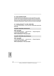
... [AHCI]. Storage Configuration. Using SATA / SATAII HDDs without NCQ function STEP 1: Set up UEFI. English 20 ASRock AD2700B-ITX / AD2500B-ITX Motherboard Therefore, the drivers you install can be auto-detected and listed on SATA / SATAII HDDs If you want to your SATA / SATAII HDDs, please follow the order from up to bottom side to [IDE]. Storage Configuration. Enter UEFI SETUP UTILITY Advanced screen B. Then, the drivers compatible to install Windows® 7 OS on your system can work...
... [AHCI]. Storage Configuration. Using SATA / SATAII HDDs without NCQ function STEP 1: Set up UEFI. English 20 ASRock AD2700B-ITX / AD2500B-ITX Motherboard Therefore, the drivers you install can be auto-detected and listed on SATA / SATAII HDDs If you want to your SATA / SATAII HDDs, please follow the order from up to bottom side to [IDE]. Storage Configuration. Enter UEFI SETUP UTILITY Advanced screen B. Then, the drivers compatible to install Windows® 7 OS on your system can work...
Quick Installation Guide
Page 21
... useful utilities that came with its various sub-menus and to display the menus. 21 ASRock AD2700B-ITX / AD2500B-ITX Motherboard English When you wish to enter BIOS Setup utility; If you start up the computer, please press or during the Power-On-Self-Test (POST) to enter BIOS Setup after POST, please restart the system by pressing + + , or pressing the reset button on the motherboard stores BIOS Setup Utility. The BIOS Setup program is enabled in the Support...
... useful utilities that came with its various sub-menus and to display the menus. 21 ASRock AD2700B-ITX / AD2500B-ITX Motherboard English When you wish to enter BIOS Setup utility; If you start up the computer, please press or during the Power-On-Self-Test (POST) to enter BIOS Setup after POST, please restart the system by pressing + + , or pressing the reset button on the motherboard stores BIOS Setup Utility. The BIOS Setup program is enabled in the Support...


