User Manual
Page 12
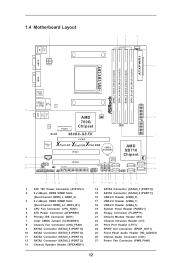
... x 240-pin DDR3 DIMM Slots (Dual Channel: DDR3_A1, DDR3_B1) 4 CPU Fan Connector (CPU_FAN1) 5 ATX Power Connector (ATXPWR1) 6 Primary IDE Connector (IDE1) 7 Clear CMOS Jumper (CLRCMOS1) 8 Chassis Fan Connector (CHA_FAN1) 9 SATA2 Connector (SATAII_6 (PORT 5)) 10 SATA2 Connector (SATAII_5 (PORT 4)) 11 SATA2 Connector (SATAII_4 (PORT 3)) 12 SATA2 Connector (SATAII_3 (PORT 2)) 13 Chassis Speaker Header (SPEAKER1) 19 18 17 16 15 14 13 12 11 14 SATA2 Connector (SATAII_1 (PORT 0)) 15 SATA2 Connector (SATAII_2 (PORT 1)) 16 USB 2.0 Header (USB8_9) 17 USB 2.0 Header (USB6_7) 18 USB 2.0 Header (USB4_5...
... x 240-pin DDR3 DIMM Slots (Dual Channel: DDR3_A1, DDR3_B1) 4 CPU Fan Connector (CPU_FAN1) 5 ATX Power Connector (ATXPWR1) 6 Primary IDE Connector (IDE1) 7 Clear CMOS Jumper (CLRCMOS1) 8 Chassis Fan Connector (CHA_FAN1) 9 SATA2 Connector (SATAII_6 (PORT 5)) 10 SATA2 Connector (SATAII_5 (PORT 4)) 11 SATA2 Connector (SATAII_4 (PORT 3)) 12 SATA2 Connector (SATAII_3 (PORT 2)) 13 Chassis Speaker Header (SPEAKER1) 19 18 17 16 15 14 13 12 11 14 SATA2 Connector (SATAII_1 (PORT 0)) 15 SATA2 Connector (SATAII_2 (PORT 1)) 16 USB 2.0 Header (USB8_9) 17 USB 2.0 Header (USB6_7) 18 USB 2.0 Header (USB4_5...

User Manual
Page 19
...: 1. Connect D-Sub monitor cable to VGA port on PCI Express VGA card driver to the steps below. Install the onboard VGA driver and the add-on the I/O panel. Right-click the display icon in the Display Properties dialog that you wish to enter BIOS setup. Enter "Share Memory" option to adjust the memory capability to [32MB], [64MB], [128MB] [256MB] or [512MB] to the corresponding connectors of VGA. A. And connect other monitor cables to enable the function of the add-on PCI Express VGA cards...
...: 1. Connect D-Sub monitor cable to VGA port on PCI Express VGA card driver to the steps below. Install the onboard VGA driver and the add-on the I/O panel. Right-click the display icon in the Display Properties dialog that you wish to enter BIOS setup. Enter "Share Memory" option to adjust the memory capability to [32MB], [64MB], [128MB] [256MB] or [512MB] to the corresponding connectors of VGA. A. And connect other monitor cables to enable the function of the add-on PCI Express VGA cards...

User Manual
Page 28
... system boot-up BIOS. D. The system will start to [RAID]. A. Formatting the floppy diskette will see the message on a RAID disk composed of 2 or more SATA / SATA2 HDDs with RAID functions, please follow below steps. B. A. Please select CD-ROM as the boot device. WARNING! Please insert a floppy diskette into the floppy drive. Therefore, the drivers you install can be auto-detected and listed on the support CD driver page. Enter BIOS SETUP UTILITY Advanced screen Storage Configuration. E. Insert the Support...
... system boot-up BIOS. D. The system will start to [RAID]. A. Formatting the floppy diskette will see the message on a RAID disk composed of 2 or more SATA / SATA2 HDDs with RAID functions, please follow below steps. B. A. Please select CD-ROM as the boot device. WARNING! Please insert a floppy diskette into the floppy drive. Therefore, the drivers you install can be auto-detected and listed on the support CD driver page. Enter BIOS SETUP UTILITY Advanced screen Storage Configuration. E. Insert the Support...
User Manual
Page 29
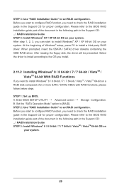
... AMD RAID driver. After reading the floppy disk, the driver will be presented. Before you start to configure RAID function, you need to check the RAID installation guide in the Support CD: .. \ RAID Installation Guide STEP 3: Install Windows® 8 / 8 64-bit / 7 / 7 64-bit / VistaTM / VistaTM 64-bit OS on your system. After step 1, 2, 3, you want to install Windows® 8 / 8 64-bit / 7 / 7 64-bit / VistaTM / VistaTM 64-bit on your system. 29 Set the "SATA Operation Mode" option to [RAID]. STEP 3: Use "RAID Installation Guide" to set RAID configuration...
... AMD RAID driver. After reading the floppy disk, the driver will be presented. Before you start to configure RAID function, you need to check the RAID installation guide in the Support CD: .. \ RAID Installation Guide STEP 3: Install Windows® 8 / 8 64-bit / 7 / 7 64-bit / VistaTM / VistaTM 64-bit OS on your system. After step 1, 2, 3, you want to install Windows® 8 / 8 64-bit / 7 / 7 64-bit / VistaTM / VistaTM 64-bit on your system. 29 Set the "SATA Operation Mode" option to [RAID]. STEP 3: Use "RAID Installation Guide" to set RAID configuration...

User Manual
Page 34
.... PCIE Frequency (MHz) Use this option to adjust CPU frequency. BIOS SETUP UTILITY Main OC Tweaker Advanced H/W Monitor Boot Security Exit CPU Configuration Overclock Mode CPU Frequency (MHz) PCIE Frequency (MHz) Spread Spectrum Boot Failure Guard Boot Failure Guard Count Advanced Clock Calibration Processor Maximum Frequency North Bridge Maximum Frequency Processor Maximum Voltage Multiplier/Voltage Change HT Bus Speed HT Bus Width Memory Configuration Memory Clock [Auto] [400] [100] [Auto] [Enabled] [3] [Disabled] x31.5 6300 MHZ x31.0 6200 MHz 1.5500 V [Auto] [Auto] [Auto] [Auto...
.... PCIE Frequency (MHz) Use this option to adjust CPU frequency. BIOS SETUP UTILITY Main OC Tweaker Advanced H/W Monitor Boot Security Exit CPU Configuration Overclock Mode CPU Frequency (MHz) PCIE Frequency (MHz) Spread Spectrum Boot Failure Guard Boot Failure Guard Count Advanced Clock Calibration Processor Maximum Frequency North Bridge Maximum Frequency Processor Maximum Voltage Multiplier/Voltage Change HT Bus Speed HT Bus Width Memory Configuration Memory Clock [Auto] [400] [100] [Auto] [Enabled] [3] [Disabled] x31.5 6300 MHZ x31.0 6200 MHz 1.5500 V [Auto] [Auto] [Auto] [Auto...

User Manual
Page 39
... context of the system caches. 3.4.1 CPU Configuration BIOS SETUP UTILITY Advanced CPU Configuration Cool' n' Quiet Secure Virtual Machine Enhanced Halt State(C1E) CPU HTC CPU Thermal Throttle [Enabled] [Enabled] [Disabled] [Enabled] [Auto] +F1 F9 F10 ESC Select Screen Select Item Change Option General Help Load Defaults Save and Exit Exit v02.54 (C) Copyright 1985-2003, American Megatrends, Inc. The C1 state is supported through the native processor instructions HLT and MWAIT and requires...
... context of the system caches. 3.4.1 CPU Configuration BIOS SETUP UTILITY Advanced CPU Configuration Cool' n' Quiet Secure Virtual Machine Enhanced Halt State(C1E) CPU HTC CPU Thermal Throttle [Enabled] [Enabled] [Disabled] [Enabled] [Auto] +F1 F9 F10 ESC Select Screen Select Item Change Option General Help Load Defaults Save and Exit Exit v02.54 (C) Copyright 1985-2003, American Megatrends, Inc. The C1 state is supported through the native processor instructions HLT and MWAIT and requires...
User Manual
Page 40
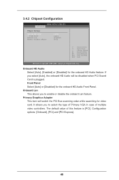
... HD Audio will switch the PCI Bus scanning order while searching for the onboard HD Audio Front Panel. Configuration options: [Onboard], [PCI] and [PCI Express]. 40 Primary Graphics Adapter This item will be disabled when PCI Sound Card is [PCI]. Front Panel Select [Auto] or [Disabled] for video card. It allows you to select the type of Primary VGA in case of this feature is plugged. Onboard HD Audio Select [Auto], [Enabled] or [Disabled] for the onboard HD Audio feature. The default value of multiple video controllers. 3.4.2 Chipset Configuration BIOS SETUP UTILITY...
... HD Audio will switch the PCI Bus scanning order while searching for the onboard HD Audio Front Panel. Configuration options: [Onboard], [PCI] and [PCI Express]. 40 Primary Graphics Adapter This item will be disabled when PCI Sound Card is [PCI]. Front Panel Select [Auto] or [Disabled] for video card. It allows you to select the type of Primary VGA in case of this feature is plugged. Onboard HD Audio Select [Auto], [Enabled] or [Disabled] for the onboard HD Audio feature. The default value of multiple video controllers. 3.4.2 Chipset Configuration BIOS SETUP UTILITY...
User Manual
Page 43
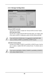
...to enable or disable SATA IDE combined mode. The default value is for SATAII_5 (PORT 4) and SATAII_6 (PORT 5) ports. The default value of this item. 43 3.4.4 Storage Configuration BIOS SETUP UTILITY Advanced Storage Configuration Onboard SATA Controller SATA Operation Mode SATA IDE Combined Mode IDE1 Master IDE1 Slave SATAII_1 SATAII_2 SATAII_3 SATAII_4 SATAII_5 SATAII_6 [Enabled] [AHCI] [Enabled] [Hard Disk] [Not Detected] [Not Detected] [Not Detected] Configure onboard serial ATA controller. +F1 F9 F10 ESC Select Screen Select Item Change Option General Help Load Defaults...
...to enable or disable SATA IDE combined mode. The default value is for SATAII_5 (PORT 4) and SATAII_6 (PORT 5) ports. The default value of this item. 43 3.4.4 Storage Configuration BIOS SETUP UTILITY Advanced Storage Configuration Onboard SATA Controller SATA Operation Mode SATA IDE Combined Mode IDE1 Master IDE1 Slave SATAII_1 SATAII_2 SATAII_3 SATAII_4 SATAII_5 SATAII_6 [Enabled] [AHCI] [Enabled] [Hard Disk] [Not Detected] [Not Detected] [Not Detected] Configure onboard serial ATA controller. +F1 F9 F10 ESC Select Screen Select Item Change Option General Help Load Defaults...
User Manual
Page 47
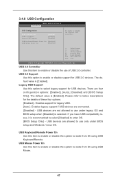
... USB Configuration BIOS SETUP UTILITY Advanced USB Configuration USB 2.0 Controller USB 2.0 Support Legacy USB Support [Enabled] [Enabled] [Enabled] USB Keyboard/Remote Power On [Disabled] USB Mouse Power On [Disabled] To enable or disable the onboard USB controllers. +F1 F9 F10 ESC Select Screen Select Item Change Option General Help Load Defaults Save and Exit Exit v02.54 (C) Copyright 1985-2005, American Megatrends, Inc. USB Mouse Power On Use this item to enable or disable the use only under legacy OS and BIOS setup when [Disabled] is recommended to select [Disabled] to wake...
... USB Configuration BIOS SETUP UTILITY Advanced USB Configuration USB 2.0 Controller USB 2.0 Support Legacy USB Support [Enabled] [Enabled] [Enabled] USB Keyboard/Remote Power On [Disabled] USB Mouse Power On [Disabled] To enable or disable the onboard USB controllers. +F1 F9 F10 ESC Select Screen Select Item Change Option General Help Load Defaults Save and Exit Exit v02.54 (C) Copyright 1985-2005, American Megatrends, Inc. USB Mouse Power On Use this item to enable or disable the use only under legacy OS and BIOS setup when [Disabled] is recommended to select [Disabled] to wake...
User Manual
Page 52
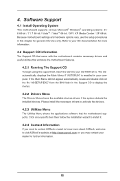
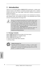
... The Support CD that came with the motherboard contains necessary drivers and useful utilities that the motherboard supports. 4. Please install the necessary drivers to your CD-ROM drive. Because motherboard settings and hardware options vary, use the setup procedures in the Support CD to visit ASRock's website at http://www.asrock.com; If the Main Menu did not appear automatically, locate and double click on a specific item then follow the installation wizard to install it...
... The Support CD that came with the motherboard contains necessary drivers and useful utilities that the motherboard supports. 4. Please install the necessary drivers to your CD-ROM drive. Because motherboard settings and hardware options vary, use the setup procedures in the Support CD to visit ASRock's website at http://www.asrock.com; If the Main Menu did not appear automatically, locate and double click on a specific item then follow the installation wizard to install it...
Quick Installation Guide
Page 2
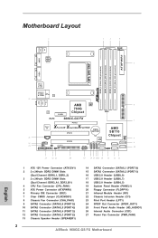
... 240-pin DDR3 DIMM Slots (Dual Channel: DDR3_A1, DDR3_B1) 4 CPU Fan Connector (CPU_FAN1) 5 ATX Power Connector (ATXPWR1) 6 Primary IDE Connector (IDE1) 7 Clear CMOS Jumper (CLRCMOS1) 8 Chassis Fan Connector (CHA_FAN1) 9 SATA2 Connector (SATAII_6 (PORT 5)) 10 SATA2 Connector (SATAII_5 (PORT 4)) 11 SATA2 Connector (SATAII_4 (PORT 3)) 12 SATA2 Connector (SATAII_3 (PORT 2)) 13 Chassis Speaker Header (SPEAKER1) 14 SATA2 Connector (SATAII_1 (PORT 0)) 15 SATA2 Connector (SATAII_2 (PORT 1)) 16 USB 2.0 Header (USB8_9) 17 USB 2.0 Header (USB6_7) 18 USB 2.0 Header (USB4_5) 19 System Panel Header (PANEL1...
... 240-pin DDR3 DIMM Slots (Dual Channel: DDR3_A1, DDR3_B1) 4 CPU Fan Connector (CPU_FAN1) 5 ATX Power Connector (ATXPWR1) 6 Primary IDE Connector (IDE1) 7 Clear CMOS Jumper (CLRCMOS1) 8 Chassis Fan Connector (CHA_FAN1) 9 SATA2 Connector (SATAII_6 (PORT 5)) 10 SATA2 Connector (SATAII_5 (PORT 4)) 11 SATA2 Connector (SATAII_4 (PORT 3)) 12 SATA2 Connector (SATAII_3 (PORT 2)) 13 Chassis Speaker Header (SPEAKER1) 14 SATA2 Connector (SATAII_1 (PORT 0)) 15 SATA2 Connector (SATAII_2 (PORT 1)) 16 USB 2.0 Header (USB8_9) 17 USB 2.0 Header (USB6_7) 18 USB 2.0 Header (USB4_5) 19 System Panel Header (PANEL1...
Quick Installation Guide
Page 4
... in Windows® 8 / 8 64-bit / 7 / 7 64-bit / VistaTM / VistaTM 64-bit, it is recommended to set the BIOS option in Storage Configuration to the "User Manual" in the Support CD. This Quick Installation Guide contains introduction of this manual occur, the updated version will be found in the user manual presented in our support CD for purchasing ASRock 960GC-GS FX motherboard, a reliable motherboard produced under ASRock's consistently stringent quality control. You may find the latest VGA cards and CPU support lists on ASRock...
... in Windows® 8 / 8 64-bit / 7 / 7 64-bit / VistaTM / VistaTM 64-bit, it is recommended to set the BIOS option in Storage Configuration to the "User Manual" in the Support CD. This Quick Installation Guide contains introduction of this manual occur, the updated version will be found in the user manual presented in our support CD for purchasing ASRock 960GC-GS FX motherboard, a reliable motherboard produced under ASRock's consistently stringent quality control. You may find the latest VGA cards and CPU support lists on ASRock...
Quick Installation Guide
Page 6
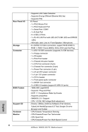
..., NB Voltage Multi-adjustment - Drivers, Utilities, AntiVirus Software (Trial Version), CyberLink MediaEspresso 6.5 Trial, Google Chrome Browser and Toolbar - English Rear Panel I /O Panel - 1 x PS/2 Mouse Port - 1 x PS/2 Keyboard Port - 1 x Serial Port: COM1 - 1 x D-Sub Port - 4 x USB 2.0 Ports - 1 x RJ-45 LAN Port with LED (ACT/LINK LED and SPEED LED) - Supports PXE I /O Storage Connector BIOS Feature Support CD Hardware Monitor 6 - Supports "Plug and Play" - ACPI 1.1 Compliance Wake Up Events - CPU/Chassis/Power Fan Multi-Speed Control ASRock 960GC-GS FX Motherboard...
..., NB Voltage Multi-adjustment - Drivers, Utilities, AntiVirus Software (Trial Version), CyberLink MediaEspresso 6.5 Trial, Google Chrome Browser and Toolbar - English Rear Panel I /O Panel - 1 x PS/2 Mouse Port - 1 x PS/2 Keyboard Port - 1 x Serial Port: COM1 - 1 x D-Sub Port - 4 x USB 2.0 Ports - 1 x RJ-45 LAN Port with LED (ACT/LINK LED and SPEED LED) - Supports PXE I /O Storage Connector BIOS Feature Support CD Hardware Monitor 6 - Supports "Plug and Play" - ACPI 1.1 Compliance Wake Up Events - CPU/Chassis/Power Fan Multi-Speed Control ASRock 960GC-GS FX Motherboard...
Quick Installation Guide
Page 9
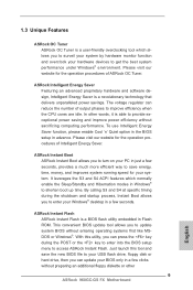
... power saving and improve power efficiency without entering operating systems first like MSDOS or Windows®. The voltage regulator can update your Windows® desktop in a few seconds, provides a much more efficient way to save the new BIOS file to your USB flash drive, floppy disk or hard drive, then you to surveil your system by hardware monitor function and overclock your system. It leverages the S3 and S4 ACPI...
... power saving and improve power efficiency without entering operating systems first like MSDOS or Windows®. The voltage regulator can update your Windows® desktop in a few seconds, provides a much more efficient way to save the new BIOS file to your USB flash drive, floppy disk or hard drive, then you to surveil your system by hardware monitor function and overclock your system. It leverages the S3 and S4 ACPI...
Quick Installation Guide
Page 13
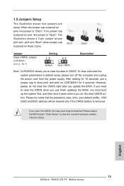
... detected. 1.5 Jumpers Setup The illustration shows how jumpers are "Short" when jumper cap is placed on pins, the jumper is "Short". Jumper Setting Description Clear CMOS Jumper (CLRCMOS1) (see p.2, No. 7) Default Clear CMOS Note: CLRCMOS1 allows you clear the CMOS, the case open may be cleared only if the CMOS battery is placed on these 2 pins. After waiting for 15 seconds, use a jumper cap to clear the data in CMOS. English 13 ASRock 960GC-GS FX Motherboard tion. If no jumper cap is...
... detected. 1.5 Jumpers Setup The illustration shows how jumpers are "Short" when jumper cap is placed on pins, the jumper is "Short". Jumper Setting Description Clear CMOS Jumper (CLRCMOS1) (see p.2, No. 7) Default Clear CMOS Note: CLRCMOS1 allows you clear the CMOS, the case open may be cleared only if the CMOS battery is placed on these 2 pins. After waiting for 15 seconds, use a jumper cap to clear the data in CMOS. English 13 ASRock 960GC-GS FX Motherboard tion. If no jumper cap is...

Quick Installation Guide
Page 17
...allows convenient connection of printer devices. English 17 ASRock 960GC-GS FX Motherboard This feature requires a chassis with chassis intrusion detection design. Chassis Speaker Header (4-pin SPEAKER 1) (see p.2, No. 13) Infrared Module Header (5-pin IR1) (see p.2, No. 21) Please connect the chassis speaker to receive stereo audio input CD1 from sound sources such as a CD-ROM, DVD-ROM, TV tuner card, or MPEG card. Internal Audio Connectors (4-pin CD1) (CD1: see p.2 No. 26) This connector allows you to this header. Chassis and Power Fan Connectors (3-pin CHA_FAN1...
...allows convenient connection of printer devices. English 17 ASRock 960GC-GS FX Motherboard This feature requires a chassis with chassis intrusion detection design. Chassis Speaker Header (4-pin SPEAKER 1) (see p.2, No. 13) Infrared Module Header (5-pin IR1) (see p.2, No. 21) Please connect the chassis speaker to receive stereo audio input CD1 from sound sources such as a CD-ROM, DVD-ROM, TV tuner card, or MPEG card. Internal Audio Connectors (4-pin CD1) (CD1: see p.2 No. 26) This connector allows you to this header. Chassis and Power Fan Connectors (3-pin CHA_FAN1...
Quick Installation Guide
Page 19
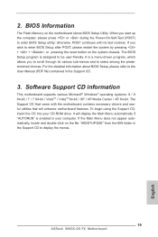
... a menu-driven program, which allows you wish to enter BIOS Setup after POST, please restart the system by pressing + + , or pressing the reset button on the file "ASSETUP.EXE" from the BIN folder in the Support CD to display the menus. 19 ASRock 960GC-GS FX Motherboard English It will enhance motherboard features. BIOS Information The Flash Memory on the motherboard stores BIOS Setup Utility. otherwise, POST continues with the motherboard contains necessary drivers and useful utilities that...
... a menu-driven program, which allows you wish to enter BIOS Setup after POST, please restart the system by pressing + + , or pressing the reset button on the file "ASSETUP.EXE" from the BIN folder in the Support CD to display the menus. 19 ASRock 960GC-GS FX Motherboard English It will enhance motherboard features. BIOS Information The Flash Memory on the motherboard stores BIOS Setup Utility. otherwise, POST continues with the motherboard contains necessary drivers and useful utilities that...
RAID Installation Guide
Page 10
... to set RAID configuration. Formatting the floppy diskette will lose ALL data in this RAID installation guide for details. STEP 3: Use "RAID Installation Guide" to install a third-party RAID driver. Please refer to format the floppy diskette and copy SATA drivers into the floppy drive. When prompted, insert the SATA driver diskette containing the AMD RAID driver. The system will be presented. Select the driver to install according to the OS you can start to the BIOS RAID installation guide part in...
... to set RAID configuration. Formatting the floppy diskette will lose ALL data in this RAID installation guide for details. STEP 3: Use "RAID Installation Guide" to install a third-party RAID driver. Please refer to format the floppy diskette and copy SATA drivers into the floppy drive. When prompted, insert the SATA driver diskette containing the AMD RAID driver. The system will be presented. Select the driver to install according to the OS you can start to the BIOS RAID installation guide part in...

RAID Installation Guide
Page 15
..., and access to configure RAID functions by using RAIDXpert RAID management software under the same directory where RAIDXpert is an instruction for you are not supported. Other brands of all programs. If you to all AMD SATA logical drives that may be present on the PC with AMD SATA RAID controllers. Insert the software CD into your networked PC in the installation dialog boxes. 6. 2. When the first installation screen appears...
..., and access to configure RAID functions by using RAIDXpert RAID management software under the same directory where RAIDXpert is an instruction for you are not supported. Other brands of all programs. If you to all AMD SATA logical drives that may be present on the PC with AMD SATA RAID controllers. Insert the software CD into your networked PC in the installation dialog boxes. 6. 2. When the first installation screen appears...

RAID Installation Guide
Page 27
... Start Menu. Then Press "Ok". 27 Windows® VistaTM 64-bit: Microsoft® does not provide hotfix for System Restore. Follow Windows® Installation Guide to boot into Windows® or install driver/utilities. Disk volume > 2TB), it may take more time to install OS. Below steps are Microsoft® suggested solution: A. a. Type "systempropertiesprotection" in a large hard disk (ex. Then Click "Turn System Restore Off" to fix this problem...
... Start Menu. Then Press "Ok". 27 Windows® VistaTM 64-bit: Microsoft® does not provide hotfix for System Restore. Follow Windows® Installation Guide to boot into Windows® or install driver/utilities. Disk volume > 2TB), it may take more time to install OS. Below steps are Microsoft® suggested solution: A. a. Type "systempropertiesprotection" in a large hard disk (ex. Then Click "Turn System Restore Off" to fix this problem...


