User Manual
Page 3
... 3.6 Security Screen 34 3.7 Exit Screen 35 3 Contents 1 . Installation 10 Pre-installation Precautions 10 2.1 CPU Installation 11 2.2 Installation of CPU Fan and Heatsink 11 2.3 Installation of Memory Modules (DIMM 12 2.4 Expansion Slots (PCI and AGP Slots 14 2.5 Jumpers Setup 15 2.6 Onboard Headers and Connectors 16 2.7 Serial ATA (SATA) Hard Disks Installation 19...
... 3.6 Security Screen 34 3.7 Exit Screen 35 3 Contents 1 . Installation 10 Pre-installation Precautions 10 2.1 CPU Installation 11 2.2 Installation of CPU Fan and Heatsink 11 2.3 Installation of Memory Modules (DIMM 12 2.4 Expansion Slots (PCI and AGP Slots 14 2.5 Jumpers Setup 15 2.6 Onboard Headers and Connectors 16 2.7 Serial ATA (SATA) Hard Disks Installation 19...
User Manual
Page 5
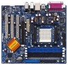
... modifications of this manual occur, the updated version will be available on ASRock website as well. You may find the latest memory and CPU support lists on ASRock website without notice. Introduction Thank you for purchasing ASRock 939A8X-M motherboard, a reliable motherboard produced under ASRock's consistently stringent quality control. Chapter 3 and 4 contain the configuration guide to the...
... modifications of this manual occur, the updated version will be available on ASRock website as well. You may find the latest memory and CPU support lists on ASRock website without notice. Introduction Thank you for purchasing ASRock 939A8X-M motherboard, a reliable motherboard produced under ASRock's consistently stringent quality control. Chapter 3 and 4 contain the configuration guide to the...
User Manual
Page 6
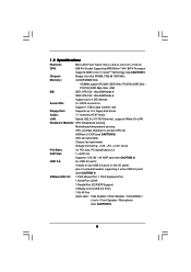
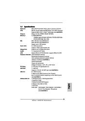
...Socket Supporting AMD AthlonTM 64 / 64FX Processor Supports AMD's Cool 'n' QuietTM Technology (see CAUTION 1) Chipset: Bridge: ULi (ALi) M1689, FSB @ 1000 MHz Memory: 4 x DDR DIMM Slots: 4 DIMMs support PC3200 (DDR 400) / PC2700 (DDR 333) / PC2100 (DDR 266), Max. 4GB IDE: IDE1: ...802.3u (10/100 Ethernet), supports Wake-On-LAN Hardware Monitor: CPU temperature sensing Motherboard temperature sensing CPU overheat shutdown to protect CPU life (ASRock U-COP)(see CAUTION 2) CPU fan tachometer Chassis fan tachometer Voltage monitoring: +12V, +5V, +3.3V, Vcore PCI Slots: 3 x PCI slots...
...Socket Supporting AMD AthlonTM 64 / 64FX Processor Supports AMD's Cool 'n' QuietTM Technology (see CAUTION 1) Chipset: Bridge: ULi (ALi) M1689, FSB @ 1000 MHz Memory: 4 x DDR DIMM Slots: 4 DIMMs support PC3200 (DDR 400) / PC2700 (DDR 333) / PC2100 (DDR 266), Max. 4GB IDE: IDE1: ...802.3u (10/100 Ethernet), supports Wake-On-LAN Hardware Monitor: CPU temperature sensing Motherboard temperature sensing CPU overheat shutdown to protect CPU life (ASRock U-COP)(see CAUTION 2) CPU fan tachometer Chassis fan tachometer Voltage monitoring: +12V, +5V, +3.3V, Vcore PCI Slots: 3 x PCI slots...
User Manual
Page 12
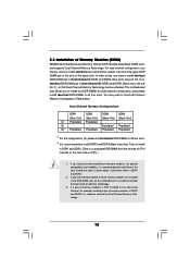
...configuration (3), please install identical DDR DIMMs in DDR1 and DDR2. (That is, to populate DDR DIMM from the far side of memory modules in DDR1 and DDR3, it is NOT installed in the same Dual Channel, for dual channel configuration, and please install identical... DDR DIMMs in the slots of Memory Modules (DIMM) 939A8X-M motherboard provides four 184-pin DDR (Double Data Rate) DIMM slots, and supports Dual Channel Memory Technology. see p.8 No. 7), so that Dual Channel Memory Technology can be activated. Dual Channel Memory Configurations DDR1 DDR2 DDR3 DDR4 (Blue Slot...
...configuration (3), please install identical DDR DIMMs in DDR1 and DDR2. (That is, to populate DDR DIMM from the far side of memory modules in DDR1 and DDR3, it is NOT installed in the same Dual Channel, for dual channel configuration, and please install identical... DDR DIMMs in the slots of Memory Modules (DIMM) 939A8X-M motherboard provides four 184-pin DDR (Double Data Rate) DIMM slots, and supports Dual Channel Memory Technology. see p.8 No. 7), so that Dual Channel Memory Technology can be activated. Dual Channel Memory Configurations DDR1 DDR2 DDR3 DDR4 (Blue Slot...
User Manual
Page 21
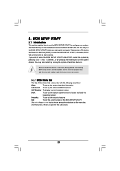
... POST, restart the system by pressing + + , or by turning the system off and then back on the motherboard stores the BIOS SETUP UTILITY. The Flash Memory on . If you start up the security features Exit To exit the current screen or the BIOS SETUP UTILITY Use < > key or < > key to choose...
... POST, restart the system by pressing + + , or by turning the system off and then back on the motherboard stores the BIOS SETUP UTILITY. The Flash Memory on . If you start up the security features Exit To exit the current screen or the BIOS SETUP UTILITY Use < > key or < > key to choose...

User Manual
Page 22
...UTILITY Main Advanced H/W Monitor Boot Security Exit System Overview System Time System Date [17:00:09] [Tue 04/26/2005] BIOS Version : 939A8X-M BIOS P1.0 Processor Type : AMD Athlon(tm) 64 Processor 3400+ Processor Speed : 2200 MHz L1 Cache Size : 128KB L2 Cache Size : ...1024KB Total Memory DIMM 1 DIMM 2 DIMM 3 DIMM 4 : 512MB Dual-Channel Memory Mode : 256MB/166MHz (DDR333) : 256MB/166MHz (DDR333) : None : None Use [Enter], [TAB] or [SHIFT-TAB] to select a ...
...UTILITY Main Advanced H/W Monitor Boot Security Exit System Overview System Time System Date [17:00:09] [Tue 04/26/2005] BIOS Version : 939A8X-M BIOS P1.0 Processor Type : AMD Athlon(tm) 64 Processor 3400+ Processor Speed : 2200 MHz L1 Cache Size : 128KB L2 Cache Size : ...1024KB Total Memory DIMM 1 DIMM 2 DIMM 3 DIMM 4 : 512MB Dual-Channel Memory Mode : 256MB/166MHz (DDR333) : 256MB/166MHz (DDR333) : None : None Use [Enter], [TAB] or [SHIFT-TAB] to select a ...

User Manual
Page 23
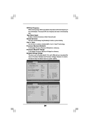
... Frequency Actual Frequency (MHz) Boot Failure Guard Spread Spectrum Cool' n' Quiet [Auto] [200] [Enabled] [Disabled] [Enabled] Processor Maximum Multiplier Processor Maximum Voltage Multiplier/Voltage Change Memory Clock Flexibility Option Burst Length CAS Latency (CL) TRCD TRAS TRP x11 1.550 V [Auto] [Auto] [Disabled] [8 Beats] [Auto] [Auto] [Auto] [Auto] Select how to set...
... Frequency Actual Frequency (MHz) Boot Failure Guard Spread Spectrum Cool' n' Quiet [Auto] [200] [Enabled] [Disabled] [Enabled] Processor Maximum Multiplier Processor Maximum Voltage Multiplier/Voltage Change Memory Clock Flexibility Option Burst Length CAS Latency (CL) TRCD TRAS TRP x11 1.550 V [Auto] [Auto] [Disabled] [8 Beats] [Auto] [Auto] [Auto] [Auto] Select how to set...
User Manual
Page 24
... Quiet [Auto] [200] [Enabled] [Disabled] [Enabled] Processor Maximum Multiplier Processor Maximum Voltage Multiplier/Voltage Change Processor Multiplier Processor Voltage Memory Clock Flexibility Option Burst Length CAS Latency (CL) TRCD x11 1.550 V [Manual] [x8] [1.500V] [Auto] [Disabled] [8 ...system stability. BIOS SETUP UTILITY Advanced Cool' n' Quiet Processor Maximum Multiplier Processor Maximum Voltage Multiplier/Voltage Change Processor Multiplier Processor Voltage Memory Clock Flexibility Option Burst Length CAS Latency (CL) TRCD TRAS TRP MA Timing [Enabled] x11 1.550 V [Manual] [x8...
... Quiet [Auto] [200] [Enabled] [Disabled] [Enabled] Processor Maximum Multiplier Processor Maximum Voltage Multiplier/Voltage Change Processor Multiplier Processor Voltage Memory Clock Flexibility Option Burst Length CAS Latency (CL) TRCD x11 1.550 V [Manual] [x8] [1.500V] [Auto] [Disabled] [8 ...system stability. BIOS SETUP UTILITY Advanced Cool' n' Quiet Processor Maximum Multiplier Processor Maximum Voltage Multiplier/Voltage Change Processor Multiplier Processor Voltage Memory Clock Flexibility Option Burst Length CAS Latency (CL) TRCD TRAS TRP MA Timing [Enabled] x11 1.550 V [Manual] [x8...

User Manual
Page 25
... be set by the code using [Auto]. Configuration options: [Auto], [2CLK], [3CLK], [4CLK], [5CLK], and [6CLK]. You may set one of memory accessing. Configuration options: [2T], [1T]. For example, if the value of "Processor Maximum Multiplier" is [x11], the actual value of "Processor Maximum Multiplier... even if you set this to [Manual]; Flexibility Option The default value of this to [Manual]; It will allow better tolerance for memory compatibility when it is not recommended to [0.800V]. TRP Use this item. Processor Multiplier This item will show when "Multiplier/Voltage Change" ...
... be set by the code using [Auto]. Configuration options: [Auto], [2CLK], [3CLK], [4CLK], [5CLK], and [6CLK]. You may set one of memory accessing. Configuration options: [2T], [1T]. For example, if the value of "Processor Maximum Multiplier" is [x11], the actual value of "Processor Maximum Multiplier... even if you set this to [Manual]; Flexibility Option The default value of this to [Manual]; It will allow better tolerance for memory compatibility when it is not recommended to [0.800V]. TRP Use this item. Processor Multiplier This item will show when "Multiplier/Voltage Change" ...

User Manual
Page 26
... will switch the PCI Bus scanning order while searching for the onboard AC97 Audio feature. It allows you to a section of the PCI memory address range used for graphics memory. The default value is [Auto]. 26 AGP Fast Write Use this field at the default value unless the installed AGP card's specifications...
... will switch the PCI Bus scanning order while searching for the onboard AC97 Audio feature. It allows you to a section of the PCI memory address range used for graphics memory. The default value is [Auto]. 26 AGP Fast Write Use this field at the default value unless the installed AGP card's specifications...
Quick Installation Guide
Page 2
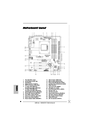
... Connector: CD1 (Black) 25 ATX Power Connector (ATXPWR1) 26 CPU Heatsink Retention Module 27 939-Pin CPU Socket 28 ATX 12V Connector (ATX12V1) 2 ASRock 939A8X-M Motherboard Motherboard Layout English 1 PS2_USB_PWR1 Jumper 2 Infrared Module Header (IR1) 3 Flash Memory 4 Floppy Connector (FLOPPY1) 5 CPU Fan Connector (CPU_FAN1) 6 2 x 184-pin DDR DIMM Slots (Dual Channel A: DDR1, DDR2;
... Connector: CD1 (Black) 25 ATX Power Connector (ATXPWR1) 26 CPU Heatsink Retention Module 27 939-Pin CPU Socket 28 ATX 12V Connector (ATX12V1) 2 ASRock 939A8X-M Motherboard Motherboard Layout English 1 PS2_USB_PWR1 Jumper 2 Infrared Module Header (IR1) 3 Flash Memory 4 Floppy Connector (FLOPPY1) 5 CPU Fan Connector (CPU_FAN1) 6 2 x 184-pin DDR DIMM Slots (Dual Channel A: DDR1, DDR2;
Quick Installation Guide
Page 4
... found in the user manual presented in Floppy Drive Ribbon Cable 1 x Serial ATA (SATA) Data Cable 1 x Serial ATA (SATA) HDD Power Cable (Optional) 1 x ASRock 8CH I/O 4 ASRock 939A8X-M Motherboard English You may find the latest memory and CPU support lists on ASRock website without notice. More detailed information of the motherboard and step-bystep installation guide.
... found in the user manual presented in Floppy Drive Ribbon Cable 1 x Serial ATA (SATA) Data Cable 1 x Serial ATA (SATA) HDD Power Cable (Optional) 1 x ASRock 8CH I/O 4 ASRock 939A8X-M Motherboard English You may find the latest memory and CPU support lists on ASRock website without notice. More detailed information of the motherboard and step-bystep installation guide.
Quick Installation Guide
Page 5
...Cool 'n' QuietTM Technology (see CAUTION 1) Chipset: Bridge: ULi (ALi) M1689, FSB @ 1000 MHz Memory: 4 x DDR DIMM Slots: 4 DIMMs support PC3200 (DDR 400) / PC2700 (DDR 333) ...Hardware Monitor: CPU temperature sensing Motherboard temperature sensing CPU overheat shutdown to protect CPU life (ASRock U-COP)(see CAUTION 2) CPU fan tachometer Chassis fan tachometer Voltage monitoring: +12V, ...2.0 ports on the I/O panel, plus 2 on-board headers supporting 4 extra USB 2.0 ports (see CAUTION 4) ASRock 8CH I/O: 1 PS/2 Mouse Port, 1 PS/2 Keyboard Port 1 Serial Port: COM1 1 Parallel Port (ECP...
...Cool 'n' QuietTM Technology (see CAUTION 1) Chipset: Bridge: ULi (ALi) M1689, FSB @ 1000 MHz Memory: 4 x DDR DIMM Slots: 4 DIMMs support PC3200 (DDR 400) / PC2700 (DDR 333) ...Hardware Monitor: CPU temperature sensing Motherboard temperature sensing CPU overheat shutdown to protect CPU life (ASRock U-COP)(see CAUTION 2) CPU fan tachometer Chassis fan tachometer Voltage monitoring: +12V, ...2.0 ports on the I/O panel, plus 2 on-board headers supporting 4 extra USB 2.0 ports (see CAUTION 4) ASRock 8CH I/O: 1 PS/2 Mouse Port, 1 PS/2 Keyboard Port 1 Serial Port: COM1 1 Parallel Port (ECP...

Quick Installation Guide
Page 8
...install DDR3 and DDR4 (black slots) first. If only one memory module or three memory modules are installed in all four slots. English 8 ASRock 939A8X-M Motherboard In other words, you want to install two different memory modules, for optimal compatibility and reliability, it is , to ...(Black Slot) (Black Slot) (1) Populated Populated - - (2) - - If a pair of Memory Modules (DIMM) 939A8X-M motherboard provides four 184-pin DDR (Double Data Rate) DIMM slots, and supports Dual Channel Memory Technology. You may refer to install identical DDR DIMM pair in DDR1 and DDR2. (That is ...
...install DDR3 and DDR4 (black slots) first. If only one memory module or three memory modules are installed in all four slots. English 8 ASRock 939A8X-M Motherboard In other words, you want to install two different memory modules, for optimal compatibility and reliability, it is , to ...(Black Slot) (Black Slot) (1) Populated Populated - - (2) - - If a pair of Memory Modules (DIMM) 939A8X-M motherboard provides four 184-pin DDR (Double Data Rate) DIMM slots, and supports Dual Channel Memory Technology. You may refer to install identical DDR DIMM pair in DDR1 and DDR2. (That is ...
Quick Installation Guide
Page 17
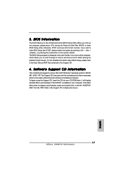
... + + , or pressing the reset button on the file "ASSETUP. For the detailed information about BIOS Setup, please refer to display the menus. 17 ASRock 939A8X-M Motherboard English It is enabled in the Support CD. 4. It will enhance motherboard features. If the Main Menu does not appear automatically, locate and double...-Self-Test (POST) to be user-friendly. To begin using the Support CD, insert the CD into your computer. BIOS Information The Flash Memory on the motherboard stores BIOS Setup Utility. The BIOS Setup program is designed to enter BIOS Setup utility;
... + + , or pressing the reset button on the file "ASSETUP. For the detailed information about BIOS Setup, please refer to display the menus. 17 ASRock 939A8X-M Motherboard English It is enabled in the Support CD. 4. It will enhance motherboard features. If the Main Menu does not appear automatically, locate and double...-Self-Test (POST) to be user-friendly. To begin using the Support CD, insert the CD into your computer. BIOS Information The Flash Memory on the motherboard stores BIOS Setup Utility. The BIOS Setup program is designed to enter BIOS Setup utility;

