User Manual
Page 4
... 57 4.1 Install Operating System 57 4.2 Support CD Information 57 4.2.1 Running Support CD 57 4.2.2 Drivers Menu 57 4.2.3 Utilities Menu 57 4.2.4 Contact Information 57 4 UEFI SETUP UTILITY 39 3.1 Introduction 39 3.1.1 UEFI Menu Bar 39 3.1.2 Navigation Keys 40 3.2 Main Screen 40 3.3 OC Tweaker Screen 41 3.4 Advanced Screen 45 3.4.1 CPU Configuration 46 3.4.2 North Bridge Configuration 47...
... 57 4.1 Install Operating System 57 4.2 Support CD Information 57 4.2.1 Running Support CD 57 4.2.2 Drivers Menu 57 4.2.3 Utilities Menu 57 4.2.4 Contact Information 57 4 UEFI SETUP UTILITY 39 3.1 Introduction 39 3.1.1 UEFI Menu Bar 39 3.1.2 Navigation Keys 40 3.2 Main Screen 40 3.3 OC Tweaker Screen 41 3.4 Advanced Screen 45 3.4.1 CPU Configuration 46 3.4.2 North Bridge Configuration 47...

User Manual
Page 7
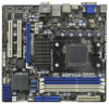
... - 4 pin 12V power connector - Supports "Plug and Play" - VCCM, NB, SB Voltage Multi-adjustment 7 Front panel audio connector - 3 x USB 2.0 headers (support 6 USB 2.0 ports) - 32Mb AMI UEFI Legal BIOS with GUI support - SMBIOS 2.3.1 Support - Atheros® AR8151 - HD Audio Jack: Rear Speaker/Central/Bass/Line in header - PCIE x1 Gigabit LAN 10...
... - 4 pin 12V power connector - Supports "Plug and Play" - VCCM, NB, SB Voltage Multi-adjustment 7 Front panel audio connector - 3 x USB 2.0 headers (support 6 USB 2.0 ports) - 32Mb AMI UEFI Legal BIOS with GUI support - SMBIOS 2.3.1 Support - Atheros® AR8151 - HD Audio Jack: Rear Speaker/Central/Bass/Line in header - PCIE x1 Gigabit LAN 10...
User Manual
Page 21
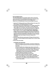
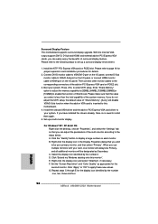
...ATITM PCI Express VGA card on VGA card is inserted to set up a multi-monitor display. Boot your system. If you do not adjust the UEFI setup, the default value of "Share Memory", [Auto], will be designated as appropriate for details. 2. If you can easily enjoy the benefits ...click the display icon and select "Attached", if necessary. Install the onboard VGA driver and the add-on PCI Express VGA card driver to enter UEFI setup. Surround Display Feature This motherboard supports surround display upgrade. Set the "Screen Resolution" and "Color Quality" as Secondary. Please refer to ...
...ATITM PCI Express VGA card on VGA card is inserted to set up a multi-monitor display. Boot your system. If you do not adjust the UEFI setup, the default value of "Share Memory", [Auto], will be designated as appropriate for details. 2. If you can easily enjoy the benefits ...click the display icon and select "Attached", if necessary. Install the onboard VGA driver and the add-on PCI Express VGA card driver to enter UEFI setup. Surround Display Feature This motherboard supports surround display upgrade. Set the "Screen Resolution" and "Color Quality" as Secondary. Please refer to ...
User Manual
Page 23
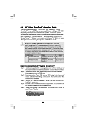
... the onboard VGA and the discrete graphics card. ATI Catalyst Control Center 23 Step 3. Step 4. Step 5. Install one compatible PCI Express graphics card to enter UEFI setup. Enter "Advanced" screen, and enter "North Bridge Configuration". Step 6. For the proper installation procedures, please refer to [Enabled]. Restart your system. Currently, ATITM Hybrid...
... the onboard VGA and the discrete graphics card. ATI Catalyst Control Center 23 Step 3. Step 4. Step 5. Install one compatible PCI Express graphics card to enter UEFI setup. Enter "Advanced" screen, and enter "North Bridge Configuration". Step 6. For the proper installation procedures, please refer to [Enabled]. Restart your system. Currently, ATITM Hybrid...
User Manual
Page 34
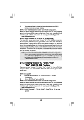
...-bit With RAID Functions If you want to install Windows® XP / XP 64-bit on a RAID disk composed of system boot-up UEFI. Then you see these messages, Please insert a blank formatted diskette into floppy drive A: press any key to start Please insert a floppy diskette... Windows® 7 / 7 64-bit / VistaTM / VistaTM 64-bit / XP / XP 64-bit With RAID Functions If you install. Insert the ASRock Support CD into the floppy drive, and press any key. 34 Enter UEFI SETUP UTILITY Advanced screen Storage Configuration. Then, the drivers compatible to [RAID]. B.
...-bit With RAID Functions If you want to install Windows® XP / XP 64-bit on a RAID disk composed of system boot-up UEFI. Then you see these messages, Please insert a blank formatted diskette into floppy drive A: press any key to start Please insert a floppy diskette... Windows® 7 / 7 64-bit / VistaTM / VistaTM 64-bit / XP / XP 64-bit With RAID Functions If you install. Insert the ASRock Support CD into the floppy drive, and press any key. 34 Enter UEFI SETUP UTILITY Advanced screen Storage Configuration. Then, the drivers compatible to [RAID]. B.
User Manual
Page 35
... (create, convert, delete, or rebuild) RAID functions on your system. STEP 2: Use "RAID Installation Guide" to set up UEFI. Select the driver to install according to [RAID]. The system will be presented. Please refer to the BIOS RAID installation guide part... Controller- STEP 1: Set up "SATA Mode" to check the RAID installation guide in the Support CD for proper configuration. A. Enter UEFI SETUP UTILITY Advanced screen Storage Configuration. At the beginning of the document in the following path in the Support CD: .. \ RAID Installation...
... (create, convert, delete, or rebuild) RAID functions on your system. STEP 2: Use "RAID Installation Guide" to set up UEFI. Select the driver to install according to [RAID]. The system will be presented. Please refer to the BIOS RAID installation guide part... Controller- STEP 1: Set up "SATA Mode" to check the RAID installation guide in the Support CD for proper configuration. A. Enter UEFI SETUP UTILITY Advanced screen Storage Configuration. At the beginning of the document in the following path in the Support CD: .. \ RAID Installation...
User Manual
Page 36
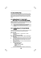
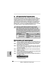
...) RAID functions on your system. Using SATAII / SATA3 HDDs with NCQ and Hot Plug functions (AHCI mode) STEP 1: Set up "SATA Mode" to [RAID] in UEFI. 2.15 Installing Windows® 7 / 7 64-bit / VistaTM / VistaTM 64-bit / XP / XP 64-bit Without RAID Functions If you install Windows® 7 / 7 64-bit / ... XP / XP 64-bit on page 34. When prompted, insert the SATA3 driver diskette containing the AMD AHCI driver. If you want to [IDE] in UEFI first. At the beginning of Windows® setup, press F6 to the OS you still need to [AHCI] for SATA3 HDDs. B. Set the "SATA Mode...
...) RAID functions on your system. Using SATAII / SATA3 HDDs with NCQ and Hot Plug functions (AHCI mode) STEP 1: Set up "SATA Mode" to [RAID] in UEFI. 2.15 Installing Windows® 7 / 7 64-bit / VistaTM / VistaTM 64-bit / XP / XP 64-bit Without RAID Functions If you install Windows® 7 / 7 64-bit / ... XP / XP 64-bit on page 34. When prompted, insert the SATA3 driver diskette containing the AMD AHCI driver. If you want to [IDE] in UEFI first. At the beginning of Windows® setup, press F6 to the OS you still need to [AHCI] for SATA3 HDDs. B. Set the "SATA Mode...

User Manual
Page 37
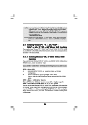
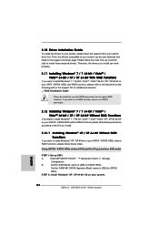
.../ 7 64-bit / VistaTM / VistaTM 64-bit on your SATAII / SATA3 HDDs without NCQ and Hot Plug functions (IDE mode) STEP 1: Set up UEFI. STEP 2: Install Windows® XP / XP 64-bit OS on your system. 2.15.2 Installing Windows® 7 / 7 64-bit / VistaTM /...HDDs with NCQ and Hot Plug functions (AHCI mode) STEP 1: Set up UEFI. Enter UEFI SETUP UTILITY Advanced screen Storage Configuration. A. A. B. Set the "SATA Mode" option to [AHCI] for SATA3 HDDs. Enter UEFI SETUP UTILITY Advanced screen Storage Configuration. Set the "ASM1061 SATA3 Operation Mode"...
.../ 7 64-bit / VistaTM / VistaTM 64-bit on your SATAII / SATA3 HDDs without NCQ and Hot Plug functions (IDE mode) STEP 1: Set up UEFI. STEP 2: Install Windows® XP / XP 64-bit OS on your system. 2.15.2 Installing Windows® 7 / 7 64-bit / VistaTM /...HDDs with NCQ and Hot Plug functions (AHCI mode) STEP 1: Set up UEFI. Enter UEFI SETUP UTILITY Advanced screen Storage Configuration. A. A. B. Set the "SATA Mode" option to [AHCI] for SATA3 HDDs. Enter UEFI SETUP UTILITY Advanced screen Storage Configuration. Set the "ASM1061 SATA3 Operation Mode"...

User Manual
Page 38
.... 38 Please refer to the warning on page 8 for the possible overclocking risk before you enable Untied Overclocking function, please enter "Overclock Mode" option of UEFI setup to set the selection from [Auto] to fixed PCI / PCIE buses. Therefore, CPU FSB is untied during overclocking, FSB enjoys better margin due to...
.... 38 Please refer to the warning on page 8 for the possible overclocking risk before you enable Untied Overclocking function, please enter "Overclock Mode" option of UEFI setup to set the selection from [Auto] to fixed PCI / PCIE buses. Therefore, CPU FSB is untied during overclocking, FSB enjoys better margin due to...
User Manual
Page 39
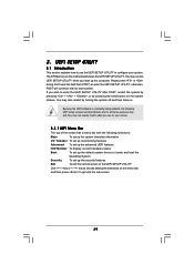
...has a menu bar with its test routines. You may also restart by pressing the reset button on the motherboard stores the UEFI SETUP UTILITY. Because the UEFI software is constantly being updated, the following selections: Main To set up the system time/date information OC Tweaker To set ...up overclocking features Advanced To set up the advanced UEFI features H/W Monitor To display current hardware status Boot To set up the default system device to locate and load the Operating System Security...
...has a menu bar with its test routines. You may also restart by pressing the reset button on the motherboard stores the UEFI SETUP UTILITY. Because the UEFI software is constantly being updated, the following selections: Main To set up the system time/date information OC Tweaker To set ...up overclocking features Advanced To set up the advanced UEFI features H/W Monitor To display current hardware status Boot To set up the default system device to locate and load the Operating System Security...
User Manual
Page 40
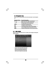
... for the function description of each navigation key. 3.1.2 Navigation Keys Please check the following table for all the settings To save changes and exit the UEFI SETUP UTILITY To jump to the Exit Screen or exit the current screen 3.2 Main Screen When you enter the...
... for the function description of each navigation key. 3.1.2 Navigation Keys Please check the following table for all the settings To save changes and exit the UEFI SETUP UTILITY To jump to the Exit Screen or exit the current screen 3.2 Main Screen When you enter the...

User Manual
Page 41
The default value is [Disabled]. As long as a simple switch of the UEFI option "ASRock UCC", you adopt. The configuration options depend on the CPU core you can unlock the extra CPU core to enjoy an instant performance boost. 3.3 OC ... 6MB, which means you can set up overclocking features. The default value is [Auto]. Please be [Auto] for reference. Configuration options: [Auto] and [Manual]. ASRock UCC ASRock UCC (Unlock CPU Core) feature simplifies AMD CPU activation. CPU Configuration Overclock Mode Use this function because some CPU, including quad-core CPU, can also...
The default value is [Disabled]. As long as a simple switch of the UEFI option "ASRock UCC", you adopt. The configuration options depend on the CPU core you can unlock the extra CPU core to enjoy an instant performance boost. 3.3 OC ... 6MB, which means you can set up overclocking features. The default value is [Auto]. Please be [Auto] for reference. Configuration options: [Auto] and [Manual]. ASRock UCC ASRock UCC (Unlock CPU Core) feature simplifies AMD CPU activation. CPU Configuration Overclock Mode Use this function because some CPU, including quad-core CPU, can also...

User Manual
Page 45
... drive, then you execute ASRock Instant Flash utility, the utility will show the UEFI files and their respective information. Please be noted that the USB flash drive or hard drive must use FAT32/16/ 12 file system. Select the proper UEFI file to malfunction. If you... a few clicks without entering operating systems first like MS-DOS or Windows®. Setting wrong values in Flash ROM. ASRock Instant Flash ASRock Instant Flash is a UEFI flash utility embedded in this section may set the configurations for the following items: CPU Configuration, North Bridge Configuration, South...
... drive, then you execute ASRock Instant Flash utility, the utility will show the UEFI files and their respective information. Please be noted that the USB flash drive or hard drive must use FAT32/16/ 12 file system. Select the proper UEFI file to malfunction. If you... a few clicks without entering operating systems first like MS-DOS or Windows®. Setting wrong values in Flash ROM. ASRock Instant Flash ASRock Instant Flash is a UEFI flash utility embedded in this section may set the configurations for the following items: CPU Configuration, North Bridge Configuration, South...

User Manual
Page 52
... USB 3.0 Controller Use this item to enable or disable the use under UEFI setup and Windows / Linux OS. If you have USB compatibility issue, it is recommended to select [Disabled] to ...enter OS. [UEFI Setup Only] - Enables legacy support if USB devices are not allowed to use of these four ...USB devices are four confi guration options: [Enabled], [Auto], [Disabled] and [UEFI Setup Only]. 3.4.7 USB Configuration USB 2.0 Controller Use this item to enable or disable the use only under legacy OS ...
... USB 3.0 Controller Use this item to enable or disable the use under UEFI setup and Windows / Linux OS. If you have USB compatibility issue, it is recommended to select [Disabled] to ...enter OS. [UEFI Setup Only] - Enables legacy support if USB devices are not allowed to use of these four ...USB devices are four confi guration options: [Enabled], [Auto], [Disabled] and [UEFI Setup Only]. 3.4.7 USB Configuration USB 2.0 Controller Use this item to enable or disable the use only under legacy OS ...
User Manual
Page 56
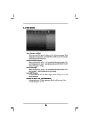
Discard Changes and Exit When you select this option, it will pop-out the following message, "Discard changes?" Load UEFI Defaults Load UEFI default values for this operation. Launch EFI Shell from one of the available filesystem devices. 56 Select [OK] to Launch EFI Shell application... (Shell64.efi) from filesystem device Attempts to save the changes and exit the UEFI SETUP UTILITY. Select [OK] to exit the UEFI SETUP UTILITY without saving any changes. F9 key can be used for all changes. Discard Changes When you select this option...
Discard Changes and Exit When you select this option, it will pop-out the following message, "Discard changes?" Load UEFI Defaults Load UEFI default values for this operation. Launch EFI Shell from one of the available filesystem devices. 56 Select [OK] to Launch EFI Shell application... (Shell64.efi) from filesystem device Attempts to save the changes and exit the UEFI SETUP UTILITY. Select [OK] to exit the UEFI SETUP UTILITY without saving any changes. F9 key can be used for all changes. Discard Changes When you select this option...
User Manual
Page 58
Please make sure to install the operating system. 1. Normally it is the device which contains your Windows® installation fi les. Set AHCI Mode in UEFI Setup Utility > Advanced > Storage Configuration > SATA Mode. 3. Start Windows® installation. 58 Please follow below procedure to use Windows® VistaTM ...64-bit (with SP1 or above) or Windows® 7 64-bit. 2. Installing OS on a HDD Larger Than 2TB This motherboard is adopting UEFI BIOS that allows Windows® OS to launch boot menu at system POST. 4. Press F11 to be installed on a large size HDD (>2TB). Choose...
Please make sure to install the operating system. 1. Normally it is the device which contains your Windows® installation fi les. Set AHCI Mode in UEFI Setup Utility > Advanced > Storage Configuration > SATA Mode. 3. Start Windows® installation. 58 Please follow below procedure to use Windows® VistaTM ...64-bit (with SP1 or above) or Windows® 7 64-bit. 2. Installing OS on a HDD Larger Than 2TB This motherboard is adopting UEFI BIOS that allows Windows® OS to launch boot menu at system POST. 4. Press F11 to be installed on a large size HDD (>2TB). Choose...
Quick Installation Guide
Page 7
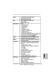
... 1.1 Compliance Wake Up Events - SMBIOS 2.3.1 Support - Front panel audio connector - 3 x USB 2.0 headers (support 6 USB 2.0 ports) - 32Mb AMI UEFI Legal BIOS with LED (ACT/LINK LED and SPEED LED) - VCCM, NB, SB Voltage Multi-adjustment 7 ASRock 880GMH/U3S3 Motherboard English Supports jumperfree - Atheros® AR8151 - CD in / Front Speaker/Microphone (see CAUTION 6) - 2 x SATA3 6.0 Gb/s connectors...
... 1.1 Compliance Wake Up Events - SMBIOS 2.3.1 Support - Front panel audio connector - 3 x USB 2.0 headers (support 6 USB 2.0 ports) - 32Mb AMI UEFI Legal BIOS with LED (ACT/LINK LED and SPEED LED) - VCCM, NB, SB Voltage Multi-adjustment 7 ASRock 880GMH/U3S3 Motherboard English Supports jumperfree - Atheros® AR8151 - CD in / Front Speaker/Microphone (see CAUTION 6) - 2 x SATA3 6.0 Gb/s connectors...
Quick Installation Guide
Page 18
...monitor cables to set up a multi-monitor display. Click the "Identify" button to your card, one , two, three and four. 18 ASRock 880GMH/U3S3 Motherboard English F. Surround Display Feature This motherboard supports surround display upgrade. Right-click the display icon in the Display Properties dialog that you can ... have installed the drivers already, there is no need to be designated as appropriate for details. 2. If you do not adjust the UEFI setup, the default value of "Share Memory", [Auto], will be your system. G. Please refer to the following steps to the ...
...monitor cables to set up a multi-monitor display. Click the "Identify" button to your card, one , two, three and four. 18 ASRock 880GMH/U3S3 Motherboard English F. Surround Display Feature This motherboard supports surround display upgrade. Right-click the display icon in the Display Properties dialog that you can ... have installed the drivers already, there is no need to be designated as appropriate for details. 2. If you do not adjust the UEFI setup, the default value of "Share Memory", [Auto], will be your system. G. Please refer to the following steps to the ...
Quick Installation Guide
Page 20
... based on an AMD 880G integrated chipset, all operating in your system. For the proper installation procedures, please refer to enter UEFI setup. Connect the monitor cable to below PCI Express graphics card support list for both the onboard VGA and the discrete graphics card... Windows® XP OS. Press to section "Expansion Slots". Restart your Windows® taskbar. English ATI Catalyst Control Center 20 ASRock 880GMH/U3S3 Motherboard Please refer to the correspondent connector on the PCI Express graphics card on your computer. Boot your system. Please remove the...
... based on an AMD 880G integrated chipset, all operating in your system. For the proper installation procedures, please refer to enter UEFI setup. Connect the monitor cable to below PCI Express graphics card support list for both the onboard VGA and the discrete graphics card... Windows® XP OS. Press to section "Expansion Slots". Restart your Windows® taskbar. English ATI Catalyst Control Center 20 ASRock 880GMH/U3S3 Motherboard Please refer to the correspondent connector on the PCI Express graphics card on your computer. Boot your system. Please remove the...
Quick Installation Guide
Page 28
... ..\ RAID Installation Guide Please be auto-detected and listed on your SATAII / SATA3 HDDs without RAID functions, please follow below steps. English 28 ASRock 880GMH/U3S3 Motherboard Then, the drivers compatible to your system can work properly. 2.11 Installing Windows® 7 / 7 64-bit / VistaTM / VistaTM ...want to [IDE] for SATA3 HDDs. A. STEP 2: Install Windows® XP / XP 64-bit OS on your system. Enter UEFI SETUP UTILITY Advanced screen Storage Configuration. Set the "SATA Mode" option to your optical drive first. Using SATAII / SATA3 HDDs without RAID...
... ..\ RAID Installation Guide Please be auto-detected and listed on your SATAII / SATA3 HDDs without RAID functions, please follow below steps. English 28 ASRock 880GMH/U3S3 Motherboard Then, the drivers compatible to your system can work properly. 2.11 Installing Windows® 7 / 7 64-bit / VistaTM / VistaTM ...want to [IDE] for SATA3 HDDs. A. STEP 2: Install Windows® XP / XP 64-bit OS on your system. Enter UEFI SETUP UTILITY Advanced screen Storage Configuration. Set the "SATA Mode" option to your optical drive first. Using SATAII / SATA3 HDDs without RAID...

