
User Manual
Page 2
... such damages arising from any defect or error in the manual or product. Operation is subject to infringe. ASRock assumes no event shall ASRock, its directors, officers, employees, or agents be liable for any indirect, special, incidental, or consequential damages... (including damages for informational use only and subject to change without intent to the following two conditions: (1) this device may not cause harmful interference, and (2) this motherboard...
... such damages arising from any defect or error in the manual or product. Operation is subject to infringe. ASRock assumes no event shall ASRock, its directors, officers, employees, or agents be liable for any indirect, special, incidental, or consequential damages... (including damages for informational use only and subject to change without intent to the following two conditions: (1) this device may not cause harmful interference, and (2) this motherboard...
User Manual
Page 3
...Modules (DIMM 17 2.4 Expansion Slots (PCI and PCI Express Slots 19 2.5 Dual Monitor and Surround Display Features 20 2.6 ATITM Hybrid CrossFireXTM Operation Guide 23 2.7 ASRock Smart Remote Installation Guide 25 2.8 Jumpers Setup 26 2.9 Onboard Headers and Connectors 27 2.10 Serial ATAII (SATAII) / Serial ATA3 (SATA3) Hard Disks Installation ... Installing Windows® 7 / 7 64-bit / VistaTM / VistaTM 64-bit Without RAID Functions 37 2.16 Untied Overclocking Technology 38 3 Introduction 5 1.1 Package Contents 5 1.2 Specifications 6 1.3 Motherboard Layout 12 1.4 I/O Panel 13 2 .
...Modules (DIMM 17 2.4 Expansion Slots (PCI and PCI Express Slots 19 2.5 Dual Monitor and Surround Display Features 20 2.6 ATITM Hybrid CrossFireXTM Operation Guide 23 2.7 ASRock Smart Remote Installation Guide 25 2.8 Jumpers Setup 26 2.9 Onboard Headers and Connectors 27 2.10 Serial ATAII (SATAII) / Serial ATA3 (SATA3) Hard Disks Installation ... Installing Windows® 7 / 7 64-bit / VistaTM / VistaTM 64-bit Without RAID Functions 37 2.16 Untied Overclocking Technology 38 3 Introduction 5 1.1 Package Contents 5 1.2 Specifications 6 1.3 Motherboard Layout 12 1.4 I/O Panel 13 2 .
User Manual
Page 5
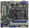
.../index.asp 1.1 Package Contents ASRock 880GMH/U3S3 Motherboard (Micro ATX Form Factor: 9.6-in x 9.0-in, 24.4 cm x 22.9 cm) ASRock 880GMH/U3S3 Quick Installation Guide ASRock 880GMH/U3S3 Support CD 2 x Serial ATA (SATA) Data Cables (Optional) 1 x I/O Panel Shield 5 In this motherboard, please visit our website for purchasing ASRock 880GMH/U3S3 motherboard, a reliable motherboard produced under ASRock's consistently stringent quality control. ASRock website http://www.asrock.com If you for specific...
.../index.asp 1.1 Package Contents ASRock 880GMH/U3S3 Motherboard (Micro ATX Form Factor: 9.6-in x 9.0-in, 24.4 cm x 22.9 cm) ASRock 880GMH/U3S3 Quick Installation Guide ASRock 880GMH/U3S3 Support CD 2 x Serial ATA (SATA) Data Cables (Optional) 1 x I/O Panel Shield 5 In this motherboard, please visit our website for purchasing ASRock 880GMH/U3S3 motherboard, a reliable motherboard produced under ASRock's consistently stringent quality control. ASRock website http://www.asrock.com If you for specific...
User Manual
Page 9
... adjust. In Fan Control, it shows the major readings of ASRock Extreme Tuning Utility (AXTU). With this motherboard supports both stereo and mono modes. For Windows® OS with your friends. ASRock Extreme Tuning Utility (AXTU) is no such limitation. 5. ASRock website: http://www.asrock.com 8. Please read the installation guide of output phases to...
... adjust. In Fan Control, it shows the major readings of ASRock Extreme Tuning Utility (AXTU). With this motherboard supports both stereo and mono modes. For Windows® OS with your friends. ASRock Extreme Tuning Utility (AXTU) is no such limitation. 5. ASRock website: http://www.asrock.com 8. Please read the installation guide of output phases to...

User Manual
Page 10
... joystick to 40% faster than before. While CPU overheat is just to install the ASRock AIWI utility either from ASRock official website or ASRock software support CD to your motherboard, and also download the free AIWI Lite from your most up to control your iPhone...touch as iPhone/iPod/iPad Touch, ASRock has prepared a wonderful solution for a more personal Internet experience. ASRock AIWI is not recommended to ASRock official website regularly, we will automatically shutdown. Also, please do -date supported games! ASRock motherboards are exclusively equipped with the SmartView...
... joystick to 40% faster than before. While CPU overheat is just to install the ASRock AIWI utility either from ASRock official website or ASRock software support CD to your motherboard, and also download the free AIWI Lite from your most up to control your iPhone...touch as iPhone/iPod/iPad Touch, ASRock has prepared a wonderful solution for a more personal Internet experience. ASRock AIWI is not recommended to ASRock official website regularly, we will automatically shutdown. Also, please do -date supported games! ASRock motherboards are exclusively equipped with the SmartView...
User Manual
Page 11
... than 50% under 1.00W in off mode condition. 15. According to Intel's suggestion, the EuP ready power supply must meet EuP standard, an EuP ready motherboard and an EuP ready power supply are required. For EuP ready power supply selection, we recommend you checking with the power supply manufacturer for the...
... than 50% under 1.00W in off mode condition. 15. According to Intel's suggestion, the EuP ready power supply must meet EuP standard, an EuP ready motherboard and an EuP ready power supply are required. For EuP ready power supply selection, we recommend you checking with the power supply manufacturer for the...
User Manual
Page 15
... remember to use a grounded wrist strap or touch a safety grounded object before touching any component, ensure that the motherboard fits into the screw holes to secure the motherboard to do so may damage the motherboard. 15 Before you handle components. 3. Hold components by the edges and do not over-tighten the screws! Failure...
... remember to use a grounded wrist strap or touch a safety grounded object before touching any component, ensure that the motherboard fits into the screw holes to secure the motherboard to do so may damage the motherboard. 15 Before you handle components. 3. Hold components by the edges and do not over-tighten the screws! Failure...
User Manual
Page 16
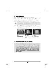
... into the socket until it is in good contact with a small triangle. The lever clicks on the socket while you install the CPU into this motherboard, it is necessary to install a larger heatsink and cooling fan to secure the CPU. Make sure that the CPU corner with the golden triangle matches...
... into the socket until it is in good contact with a small triangle. The lever clicks on the socket while you install the CPU into this motherboard, it is necessary to install a larger heatsink and cooling fan to secure the CPU. Make sure that the CPU corner with the golden triangle matches...

User Manual
Page 17
...need to install identical (the same brand, speed, size and chiptype) DDR3 DIMM pair in all four slots. 1. Blue slots; This motherboard also allows you want to install two memory modules, for optimal compatibility and reliability, it is recommended to install them in DDR3_A1 and ...It is unable to install four DDR3 DIMMs for example, installing a pair of memory modules in the slots of Memory Modules (DIMM) This motherboard provides four 240-pin DDR3 (Double Data Rate 3) DIMM slots, and supports Dual Channel Memory Technology. Dual Channel Memory Configurations DDR3_A1 DDR3_B1 (...
...need to install identical (the same brand, speed, size and chiptype) DDR3 DIMM pair in all four slots. 1. Blue slots; This motherboard also allows you want to install two memory modules, for optimal compatibility and reliability, it is recommended to install them in DDR3_A1 and ...It is unable to install four DDR3 DIMMs for example, installing a pair of memory modules in the slots of Memory Modules (DIMM) This motherboard provides four 240-pin DDR3 (Double Data Rate 3) DIMM slots, and supports Dual Channel Memory Technology. Dual Channel Memory Configurations DDR3_A1 DDR3_B1 (...
User Manual
Page 18
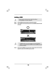
... Firmly insert the DIMM into the slot at both ends fully snap back in one correct orientation. Step 1. Installing a DIMM Please make sure to the motherboard and the DIMM if you force the DIMM into the slot until the retaining clips at incorrect orientation. Align a DIMM on the slot such that...
... Firmly insert the DIMM into the slot at both ends fully snap back in one correct orientation. Step 1. Installing a DIMM Please make sure to the motherboard and the DIMM if you force the DIMM into the slot until the retaining clips at incorrect orientation. Align a DIMM on the slot such that...
User Manual
Page 19
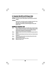
... make sure that the power supply is switched off or the power cord is already installed in a chassis). Remove the system unit cover (if your motherboard is unplugged. Keep the screws for PCI Express cards with x1 lane width cards, such as Gigabit LAN card and SATA2 card. Align the card... the card is used for the card before you intend to install expansion cards that you start the installation. Blue) is completely seated on this motherboard. Step 5. Replace the system cover. 19 Installing an expansion card Step 1. Step 2. White) is used to use .
... make sure that the power supply is switched off or the power cord is already installed in a chassis). Remove the system unit cover (if your motherboard is unplugged. Keep the screws for PCI Express cards with x1 lane width cards, such as Gigabit LAN card and SATA2 card. Align the card... the card is used for the card before you intend to install expansion cards that you start the installation. Blue) is completely seated on this motherboard. Step 5. Replace the system cover. 19 Installing an expansion card Step 1. Step 2. White) is used to use .
User Manual
Page 20
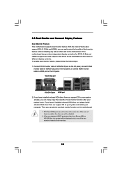
... freely enjoy the benefits of dual monitor function after your system already, you can easily enjoy the benefits of both monitors. 20 This motherboard also provides independent display controllers for DVI-D, D-Sub and HDMI to use dual monitor function on the I /O panel, or connect HDMI... your computer. To enable dual monitor feature, please follow the below steps: 1. 2.5 Dual Monitor and Surround Display Features Dual Monitor Feature This motherboard supports dual monitor feature. Connect DVI-D monitor cable to VGA/DVI-D port on the I/O panel, connect D-Sub monitor cable to VGA/D-Sub ...
... freely enjoy the benefits of dual monitor function after your system already, you can easily enjoy the benefits of both monitors. 20 This motherboard also provides independent display controllers for DVI-D, D-Sub and HDMI to use dual monitor function on the I /O panel, or connect HDMI... your computer. To enable dual monitor feature, please follow the below steps: 1. 2.5 Dual Monitor and Surround Display Features Dual Monitor Feature This motherboard supports dual monitor feature. Connect DVI-D monitor cable to VGA/DVI-D port on the I/O panel, connect D-Sub monitor cable to VGA/D-Sub ...
User Manual
Page 21
... the parameters of surround display feature. F. Repeat steps C through E for the diaplay icon identified by the number 2. Surround Display Feature This motherboard supports surround display upgrade. Install the ATITM PCI Express VGA card on PCI Express VGA cards, you use multiple monitors with your system. Boot ... that the value you do not adjust the UEFI setup, the default value of VGA/D-sub. Click "Extend my Windows desktop onto this motherboard. 4. Right-click the display icon and select "Attached", if necessary. Please refer to the following steps to HDMI port on PCI Express...
... the parameters of surround display feature. F. Repeat steps C through E for the diaplay icon identified by the number 2. Surround Display Feature This motherboard supports surround display upgrade. Install the ATITM PCI Express VGA card on PCI Express VGA cards, you use multiple monitors with your system. Boot ... that the value you do not adjust the UEFI setup, the default value of VGA/D-sub. Click "Extend my Windows desktop onto this motherboard. 4. Right-click the display icon and select "Attached", if necessary. Please refer to the following steps to HDMI port on PCI Express...
User Manual
Page 22
... drag the display icons to positions representing the physical setup of your change. HDCP Function HDCP function is supported on this motherboard, you need to use HDCP function with this motherboard. Therefore, you move items from one monitor to the steps below instruction for more details about HDCP function. In other words...
... drag the display icons to positions representing the physical setup of your change. HDCP Function HDCP function is supported on this motherboard, you need to use HDCP function with this motherboard. Therefore, you move items from one monitor to the steps below instruction for more details about HDCP function. In other words...
User Manual
Page 23
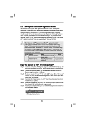
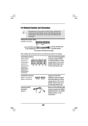
...174; XP OS. An ATITM Hybrid CrossFireXTM system includes an ATITM RadeonTM 2400 or ATITM RadeonTM 3450 series graphics processor and a motherboard based on an AMD 880G integrated chipset, all operating in your system. For the future update of ATITM Hybrid CrossFireXTM Step 1...." to below PCI Express graphics card support list for further information. Please refer to [Enabled]. 2.6 ATITM Hybrid CrossFireXTM Operation Guide This motherboard supports ATITM Hybrid CrossFireXTM feature. Currently, ATITM Hybrid CrossFireXTM Technology is only supported with Windows® VistaTM / 7 OS, and is ...
...174; XP OS. An ATITM Hybrid CrossFireXTM system includes an ATITM RadeonTM 2400 or ATITM RadeonTM 3450 series graphics processor and a motherboard based on an AMD 880G integrated chipset, all operating in your system. For the future update of ATITM Hybrid CrossFireXTM Step 1...." to below PCI Express graphics card support list for further information. Please refer to [Enabled]. 2.6 ATITM Hybrid CrossFireXTM Operation Guide This motherboard supports ATITM Hybrid CrossFireXTM feature. Currently, ATITM Hybrid CrossFireXTM Technology is only supported with Windows® VistaTM / 7 OS, and is ...
User Manual
Page 25
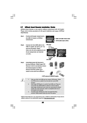
... to the USB 2.0 header on the market. 3. 2.7 ASRock Smart Remote Installation Guide ASRock Smart Remote is used for ASRock motherboard with most of ASRock motherboards. Find the CIR header located next to connect it before you boot the system. * ASRock Smart Remote is enabled, the other front USB port. 3...2.0 header (9-pin, blue) CIR header (4-pin, white) Step2. When the CIR function is only supported by some of the chassis on ASRock motherboard. The Multi-Angle CIR Receiver does not support Hot-Plug function. USB_PWR PP+ GND DUMMY 1 23 45 GND IRTX IRRX ATX+5VSB Step3...
... to the USB 2.0 header on the market. 3. 2.7 ASRock Smart Remote Installation Guide ASRock Smart Remote is used for ASRock motherboard with most of ASRock motherboards. Find the CIR header located next to connect it before you boot the system. * ASRock Smart Remote is enabled, the other front USB port. 3...2.0 header (9-pin, blue) CIR header (4-pin, white) Step2. When the CIR function is only supported by some of the chassis on ASRock motherboard. The Multi-Angle CIR Receiver does not support Hot-Plug function. USB_PWR PP+ GND DUMMY 1 23 45 GND IRTX IRRX ATX+5VSB Step3...
User Manual
Page 27
Serial ATA (SATA) Data Cable (Optional) Either end of the motherboard! The current SATAII interface allows up to 3.0 Gb/s data transfer rate. The current SATA3 interface allows up to 6.0 Gb/s data transfer rate. Do NOT place ...) (SATAII_3 (PORT 2): see p.12, No. 17) (SATAII_4 (PORT 3): see p.12, No. 16) (SATAII_5 (PORT 4): see p.12 No. 8) PIN1 IDE1 connect the blue end to the motherboard connect the black end to the IDE devices 80-conductor ATA 66/100/133 cable Note: Please refer to the SATAII / SATA3 hard disk or...
Serial ATA (SATA) Data Cable (Optional) Either end of the motherboard! The current SATAII interface allows up to 3.0 Gb/s data transfer rate. The current SATA3 interface allows up to 6.0 Gb/s data transfer rate. Do NOT place ...) (SATAII_3 (PORT 2): see p.12, No. 17) (SATAII_4 (PORT 3): see p.12, No. 16) (SATAII_5 (PORT 4): see p.12 No. 8) PIN1 IDE1 connect the blue end to the motherboard connect the black end to the IDE devices 80-conductor ATA 66/100/133 cable Note: Please refer to the SATAII / SATA3 hard disk or...
User Manual
Page 28
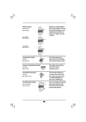
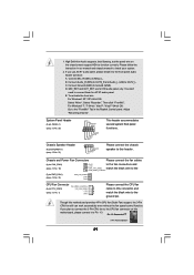
.... 32) GND PRESENCE# MIC_RET OUT_RET 1 OUT2_L J_SENSE OUT2_R MIC2_R MIC2_L Besides four default USB 2.0 ports on the I/O panel, there are three USB 2.0 headers on this motherboard.
.... 32) GND PRESENCE# MIC_RET OUT_RET 1 OUT2_L J_SENSE OUT2_R MIC2_R MIC2_L Besides four default USB 2.0 ports on the I/O panel, there are three USB 2.0 headers on this motherboard.
User Manual
Page 29
.... 20) Chassis Speaker Header (4-pin SPEAKER 1) (see p.12 No. 1) Please connect the CPU fan 4 3 cable to this motherboard, please connect it to the front panel audio header as below: A. Connect Mic_IN (MIC) to this motherboard provides 4-Pin CPU fan (Quiet Fan) support, the 3-Pin CPU fan still can work successfully even without...
.... 20) Chassis Speaker Header (4-pin SPEAKER 1) (see p.12 No. 1) Please connect the CPU fan 4 3 cable to this motherboard, please connect it to the front panel audio header as below: A. Connect Mic_IN (MIC) to this motherboard provides 4-Pin CPU fan (Quiet Fan) support, the 3-Pin CPU fan still can work successfully even without...

User Manual
Page 30
... Power Connector (4-pin ATX12V1) (see p.12 No. 2) Serial port Header (9-pin COM1) (see p.12 No. 7) 12 24 Please connect an ATX power supply to this motherboard provides 24-pin ATX power connector, 12 24 it can still work if you adopt a traditional 20-pin ATX power supply. This COM1 header supports...
... Power Connector (4-pin ATX12V1) (see p.12 No. 2) Serial port Header (9-pin COM1) (see p.12 No. 7) 12 24 Please connect an ATX power supply to this motherboard provides 24-pin ATX power connector, 12 24 it can still work if you adopt a traditional 20-pin ATX power supply. This COM1 header supports...

