User Manual
Page 8
... OS - Intelligent Energy Saver (see CAUTION 15) * For detailed product information, please visit our website: http://www.asrock.com 8 Instant Boot - Chassis Temperature Sensing - CPU/Chassis/Power Fan Tachometer - ErP/EuP Ready (ErP/EuP ready power supply is required) (see CAUTION 10) - Supports "Plug and Play" - CPU, VCCM, NB, SB Voltage Multi-adjustment Support...
... OS - Intelligent Energy Saver (see CAUTION 15) * For detailed product information, please visit our website: http://www.asrock.com 8 Instant Boot - Chassis Temperature Sensing - CPU/Chassis/Power Fan Tachometer - ErP/EuP Ready (ErP/EuP ready power supply is required) (see CAUTION 10) - Supports "Plug and Play" - CPU, VCCM, NB, SB Voltage Multi-adjustment Support...
User Manual
Page 10
.... The software name itself - Although this tool and save the new BIOS file to access ASRock Instant Flash. According to save your friends! For EuP ready power supply selection, we recommend you can update your overclocking record under the operating system and simplifies the ... you to Intel's suggestion, the EuP ready power supply must use Intelligent Energy Saver function, please enable Cool 'n' Quiet option in the BIOS setup in Flash ROM. EuP, stands for Energy Using Product, was a provision regulated by ASRock, provides a convenient way for the completed system...
.... The software name itself - Although this tool and save the new BIOS file to access ASRock Instant Flash. According to save your friends! For EuP ready power supply selection, we recommend you can update your overclocking record under the operating system and simplifies the ... you to Intel's suggestion, the EuP ready power supply must use Intelligent Energy Saver function, please enable Cool 'n' Quiet option in the BIOS setup in Flash ROM. EuP, stands for Energy Using Product, was a provision regulated by ASRock, provides a convenient way for the completed system...

User Manual
Page 14
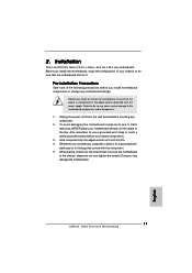
... due to use a grounded wrist strap or touch a safety grounded object before touching any component, ensure that the power is switched off or the power cord is an ATX form factor (12.0-in x 9.6-in the bag that the motherboard fits into the screw holes... Whenever you handle components. 3. Installation This is detached from the wall socket before you uninstall any motherboard settings. Unplug the power cord from the power supply. Also remember to static electricity, NEVER place your chassis to ensure that comes with the component. 5. Pre-installation Precautions Take...
... due to use a grounded wrist strap or touch a safety grounded object before touching any component, ensure that the power is switched off or the power cord is an ATX form factor (12.0-in x 9.6-in the bag that the motherboard fits into the screw holes... Whenever you handle components. 3. Installation This is detached from the wall socket before you uninstall any motherboard settings. Unplug the power cord from the power supply. Also remember to static electricity, NEVER place your chassis to ensure that comes with the component. 5. Pre-installation Precautions Take...

User Manual
Page 17
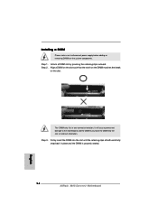
... orientation. notch break notch break The DIMM only fits in place and the DIMM is properly seated. 17 It will cause permanent damage to disconnect power supply before adding or removing DIMMs or the system components. Firmly insert the DIMM into the slot at both ends fully snap back in one correct...
... orientation. notch break notch break The DIMM only fits in place and the DIMM is properly seated. 17 It will cause permanent damage to disconnect power supply before adding or removing DIMMs or the system components. Firmly insert the DIMM into the slot at both ends fully snap back in one correct...

User Manual
Page 18
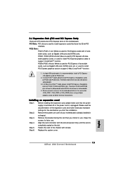
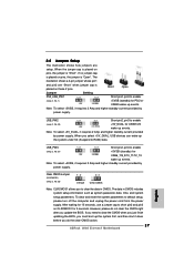
... PCI Express graphics cards to support 3-Way CrossFireXTM function. 1. Step 2. Please read the documentation of the expansion card and make sure that the power supply is switched off or the power cord is already installed in a chassis). 2.4 Expansion Slots (PCI and PCI Express Slots) There are used to install expansion cards that have...
... PCI Express graphics cards to support 3-Way CrossFireXTM function. 1. Step 2. Please read the documentation of the expansion card and make sure that the power supply is switched off or the power cord is already installed in a chassis). 2.4 Expansion Slots (PCI and PCI Express Slots) There are used to install expansion cards that have...
User Manual
Page 30
..., No. 43) +5V_DUAL for PS/2 or USB45 wake up events. Note: To select +5V_DUAL, it requires 2 Amp and higher standby current provided by power supply. When you must boot up the system under S3 (Suspend to enable +5VSB (standby) for 5 seconds. If no jumper cap is placed on pins,... BIOS, you select +5V_DUAL, USB devices can wake up the system first, and then shut it requires 2 Amp and higher standby current provided by power supply. USB_PW3 (see p.11, No. 25) Default Clear CMOS Note: CLRCMOS1 allows you update the BIOS. The illustration shows a 3-pin jumper whose pin1...
..., No. 43) +5V_DUAL for PS/2 or USB45 wake up events. Note: To select +5V_DUAL, it requires 2 Amp and higher standby current provided by power supply. When you must boot up the system under S3 (Suspend to enable +5VSB (standby) for 5 seconds. If no jumper cap is placed on pins,... BIOS, you select +5V_DUAL, USB devices can wake up the system first, and then shut it requires 2 Amp and higher standby current provided by power supply. USB_PW3 (see p.11, No. 25) Default Clear CMOS Note: CLRCMOS1 allows you update the BIOS. The illustration shows a 3-pin jumper whose pin1...
User Manual
Page 34
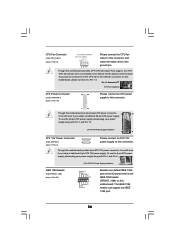
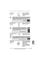
... on this motherboard, please connect it to Pin 1-3. Pin 1-3 Connected 3-Pin Fan Installation ATX Power Connector (24-pin ATXPWR1) (see p.11 No. 10) 12 24 Please connect an ATX power supply to this connector. 1 13 Though this connector and match the black wire to the ground pin... even without the fan speed control function. To use the 20-pin ATX power supply, please plug your power supply along with Pin 1 and Pin 5. 8 5 IEEE 1394 Header (9-pin FRONT_1394) (see p.11 No. 24) 4-Pin ATX 12V Power Supply Installation 4 1 RXTPAM_0 GND RXTPBM_0 +12V GND 1 +12V RXTPBP_0 GND RXTPAP_0...
... on this motherboard, please connect it to Pin 1-3. Pin 1-3 Connected 3-Pin Fan Installation ATX Power Connector (24-pin ATXPWR1) (see p.11 No. 10) 12 24 Please connect an ATX power supply to this connector. 1 13 Though this connector and match the black wire to the ground pin... even without the fan speed control function. To use the 20-pin ATX power supply, please plug your power supply along with Pin 1 and Pin 5. 8 5 IEEE 1394 Header (9-pin FRONT_1394) (see p.11 No. 24) 4-Pin ATX 12V Power Supply Installation 4 1 RXTPAM_0 GND RXTPBM_0 +12V GND 1 +12V RXTPBP_0 GND RXTPAP_0...
User Manual
Page 42
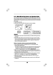
... cannot support Hot Plug function, will cause the HDD damage and data loss. Without SATA 15-pin power connector interface, the SATA3 Hot Plug cannot be supported by step to power supply 1. Please make sure the SATA3 driver is definitely not able to support Hot Plug and will be damaged...function from the motherboard gift box pack. Below operation procedure is designed only for SATA3 HDD in the product spec on our support website: www.asrock.com 4. SATA data cable (Red) B. Please follow below operation guide of attention, before you process the SATA3 HDD Hot Plug, please ...
... cannot support Hot Plug function, will cause the HDD damage and data loss. Without SATA 15-pin power connector interface, the SATA3 Hot Plug cannot be supported by step to power supply 1. Please make sure the SATA3 driver is definitely not able to support Hot Plug and will be damaged...function from the motherboard gift box pack. Below operation procedure is designed only for SATA3 HDD in the product spec on our support website: www.asrock.com 4. SATA data cable (Red) B. Please follow below operation guide of attention, before you process the SATA3 HDD Hot Plug, please ...

User Manual
Page 43
... data cable to the power supply 1x4-pin cable. Step 1 Please connect SATA power cable 1x4-pin end Step 2 Connect SATA data cable to (White) to the SATA3 HDD. Step 2 Unplug SATA 15-pin power cable connector (Black) from SATA3 HDD side. SATA power cable 1x4-pin power connector (White) Step ...3 Connect SATA 15-pin power cable connector (Black) end to process the Hot Unplug, improper procedure will cause the...
... data cable to the power supply 1x4-pin cable. Step 1 Please connect SATA power cable 1x4-pin end Step 2 Connect SATA data cable to (White) to the SATA3 HDD. Step 2 Unplug SATA 15-pin power cable connector (Black) from SATA3 HDD side. SATA power cable 1x4-pin power connector (White) Step ...3 Connect SATA 15-pin power cable connector (Black) end to process the Hot Unplug, improper procedure will cause the...
User Manual
Page 59
...] Enabling this function may reduce CPU voltage and memory frequency, and lead to system stability or compatibility issue with some memory modules or power supplies. Please note that enabling this option is set this item to [Enabled], a VMM (Virtual Machine Architecture) can utilize the additional hardware... function may reduce CPU voltage and memory freq., and lead to system stability or compatibility issue with some memory modules or power supplies. The C1 state is [Auto]. L3 Cache Allocation The default value is supported through the native processor instructions HLT and ...
...] Enabling this function may reduce CPU voltage and memory frequency, and lead to system stability or compatibility issue with some memory modules or power supplies. Please note that enabling this option is set this item to [Enabled], a VMM (Virtual Machine Architecture) can utilize the additional hardware... function may reduce CPU voltage and memory freq., and lead to system stability or compatibility issue with some memory modules or power supplies. The C1 state is [Auto]. L3 Cache Allocation The default value is supported through the native processor instructions HLT and ...
Quick Installation Guide
Page 8
... (see CAUTION 15) * For detailed product information, please visit our website: http://www.asrock.com English 8 ASRock 880G Extreme3 Motherboard CPU Quiet Fan - FCC, CE, WHQL - Explorer, AMD Fusion, ASRock Software Suite (CyberLink DVD Suite - Instant Boot - ErP/EuP Ready (ErP/EuP ready power supply is required) (see CAUTION 12) - Supports "Plug and Play" - Trial) Unique Feature...
... (see CAUTION 15) * For detailed product information, please visit our website: http://www.asrock.com English 8 ASRock 880G Extreme3 Motherboard CPU Quiet Fan - FCC, CE, WHQL - Explorer, AMD Fusion, ASRock Software Suite (CyberLink DVD Suite - Instant Boot - ErP/EuP Ready (ErP/EuP ready power supply is required) (see CAUTION 12) - Supports "Plug and Play" - Trial) Unique Feature...
Quick Installation Guide
Page 10
...share with your OC settings as yours! It helps you checking with the power supply manufacturer for Energy Using Product, was a provision regulated by ASRock, provides a convenient way for the user to define the power consumption for the operation procedures of the completed system shall be shared and...their own system to save your friends! Frequencies other words, it back again. EuP, stands for more details. 10 ASRock 880G Extreme3 Motherboard English For EuP ready power supply selection, we recommend you to get the same OC settings as a profile and share with others.
...share with your OC settings as yours! It helps you checking with the power supply manufacturer for Energy Using Product, was a provision regulated by ASRock, provides a convenient way for the user to define the power consumption for the operation procedures of the completed system shall be shared and...their own system to save your friends! Frequencies other words, it back again. EuP, stands for more details. 10 ASRock 880G Extreme3 Motherboard English For EuP ready power supply selection, we recommend you to get the same OC settings as a profile and share with others.
Quick Installation Guide
Page 11
Before you uninstall any component, ensure that the power is switched off or the power cord is an ATX form factor (12.0-in x 9.6-in the bag that the motherboard fits into the screw holes to secure the ...and do so may damage the motherboard. 11 ASRock 880G Extreme3 Motherboard English Before you install the motherboard, study the configuration of the following precautions before you handle components. 3. Installation This is detached from the wall socket before you install motherboard components or change any component. 2. Unplug the power cord from the power supply.
Before you uninstall any component, ensure that the power is switched off or the power cord is an ATX form factor (12.0-in x 9.6-in the bag that the motherboard fits into the screw holes to secure the ...and do so may damage the motherboard. 11 ASRock 880G Extreme3 Motherboard English Before you install the motherboard, study the configuration of the following precautions before you handle components. 3. Installation This is detached from the wall socket before you install motherboard components or change any component. 2. Unplug the power cord from the power supply.
Quick Installation Guide
Page 14
... a DIMM slot by pressing the retaining clips outward. The DIMM only fits in place and the DIMM is properly seated. 14 ASRock 880G Extreme3 Motherboard English It will cause permanent damage to disconnect power supply before adding or removing DIMMs or the system components. Step 2. Installing a DIMM Please make sure to the motherboard and the...
... a DIMM slot by pressing the retaining clips outward. The DIMM only fits in place and the DIMM is properly seated. 14 ASRock 880G Extreme3 Motherboard English It will cause permanent damage to disconnect power supply before adding or removing DIMMs or the system components. Step 2. Installing a DIMM Please make sure to the motherboard and the...
Quick Installation Guide
Page 15
...on the slot. Installing an expansion card Step 1. Please read the documentation of the expansion card and make sure that the power supply is switched off or the power cord is already installed in a chassis). Step 3. Step 6. PCI Slots: PCI slots are 3 PCI slots and 4 ...better thermal environment. White) is completely seated on PCIE2 slot. 2. PCIE2 / PCIE3 (PCIE x16 slot; Replace the system cover. 15 ASRock 880G Extreme3 Motherboard English Therefore, PCIE2 and PCIE3 slots will work at x8 bandwidth while PCIE4 slot will work at x8 bandwidth. 3. In single VGA...
...on the slot. Installing an expansion card Step 1. Please read the documentation of the expansion card and make sure that the power supply is switched off or the power cord is already installed in a chassis). Step 3. Step 6. PCI Slots: PCI slots are 3 PCI slots and 4 ...better thermal environment. White) is completely seated on PCIE2 slot. 2. PCIE2 / PCIE3 (PCIE x16 slot; Replace the system cover. 15 ASRock 880G Extreme3 Motherboard English Therefore, PCIE2 and PCIE3 slots will work at x8 bandwidth while PCIE4 slot will work at x8 bandwidth. 3. In single VGA...
Quick Installation Guide
Page 27
... CMOS when you just finish updating the BIOS, you update the BIOS. Note: To select +5V_DUAL, it requires 2 Amp and higher standby current provided by power supply. USB_PW3 Short pin2, pin3 to enable (see p.2, No. 43) +5V_DUAL for 15 seconds, use a jumper cap to enable (see p.2, No. 27) ...the jumper is "Short". When you to default setup, please turn off the computer and unplug the power cord from the power supply. However, please do the clear-CMOS action. 27 ASRock 880G Extreme3 Motherboard If no jumper cap is placed on pins, the jumper is placed on these 2 pins. When...
... CMOS when you just finish updating the BIOS, you update the BIOS. Note: To select +5V_DUAL, it requires 2 Amp and higher standby current provided by power supply. USB_PW3 Short pin2, pin3 to enable (see p.2, No. 43) +5V_DUAL for 15 seconds, use a jumper cap to enable (see p.2, No. 27) ...the jumper is "Short". When you to default setup, please turn off the computer and unplug the power cord from the power supply. However, please do the clear-CMOS action. 27 ASRock 880G Extreme3 Motherboard If no jumper cap is placed on pins, the jumper is placed on these 2 pins. When...
Quick Installation Guide
Page 31
... power supply, please plug your power supply along with Pin 1 and Pin 13. 20-Pin ATX Power Supply Installation 1 13 ATX 12V Power Connector 8 5 (8-pin ATX12V1) (see p.2 No. 24) 4-Pin ATX 12V Power Supply Installation 4 1 Besides one default IEEE 1394 port on the I/O panel, there is one IEEE 1394 port. English 31 ASRock 880G Extreme3 Motherboard To use the 20-pin ATX power supply...
... power supply, please plug your power supply along with Pin 1 and Pin 13. 20-Pin ATX Power Supply Installation 1 13 ATX 12V Power Connector 8 5 (8-pin ATX12V1) (see p.2 No. 24) 4-Pin ATX 12V Power Supply Installation 4 1 Besides one default IEEE 1394 port on the I/O panel, there is one IEEE 1394 port. English 31 ASRock 880G Extreme3 Motherboard To use the 20-pin ATX power supply...

