User Manual
Page 3
Installation 14 Pre-installation Precautions 14 2.1 CPU Installation 15 2.2 Installation of CPU Fan and Heatsink 15 2.3 Installation of Memory Modules (DIMM 16 2.4 Expansion Slots (PCI and PCI Express Slots 18 2.5 Dual Monitor and Surround Display Features 19 2.6 ...
Installation 14 Pre-installation Precautions 14 2.1 CPU Installation 15 2.2 Installation of CPU Fan and Heatsink 15 2.3 Installation of Memory Modules (DIMM 16 2.4 Expansion Slots (PCI and PCI Express Slots 18 2.5 Dual Monitor and Surround Display Features 19 2.6 ...
User Manual
Page 4
... Information 72 4 BIOS SETUP UTILITY 48 3.1 Introduction 48 3.1.1 BIOS Menu Bar 48 3.1.2 Navigation Keys 49 3.2 Main Screen 49 3.3 OC Tweaker Screen 50 3.4 Advanced Screen 58 3.4.1 CPU Configuration 59 3.4.2 Chipset Configuration 60 3.4.3 ACPI Configuration 62 3.4.4 Storage Configuration 63 3.4.5 PCIPnP Configuration 65 3.4.6 Super IO Configuration 66 3.4.7 USB Configuration 67 3.5 Hardware Health Event Monitoring...
... Information 72 4 BIOS SETUP UTILITY 48 3.1 Introduction 48 3.1.1 BIOS Menu Bar 48 3.1.2 Navigation Keys 49 3.2 Main Screen 49 3.3 OC Tweaker Screen 50 3.4 Advanced Screen 58 3.4.1 CPU Configuration 59 3.4.2 Chipset Configuration 60 3.4.3 ACPI Configuration 62 3.4.4 Storage Configuration 63 3.4.5 PCIPnP Configuration 65 3.4.6 Super IO Configuration 66 3.4.7 USB Configuration 67 3.5 Hardware Health Event Monitoring...
User Manual
Page 5
...find the latest VGA cards and CPU support lists on ASRock website without notice. www.asrock.com/support/index.asp 1.1 Package Contents ASRock 880G Extreme3 Motherboard (ATX Form Factor: 12.0-in x 9.6-in, 30.5 cm x 24.4 cm) ASRock 880G Extreme3 Quick Installation Guide ASRock 880G Extreme3 Support CD 4 x Serial ATA...and step-by-step guide to this motherboard, please visit our website for purchasing ASRock 880G Extreme3 motherboard, a reliable motherboard produced under ASRock's consistently stringent quality control. Because the motherboard specifications and the BIOS software might ...
...find the latest VGA cards and CPU support lists on ASRock website without notice. www.asrock.com/support/index.asp 1.1 Package Contents ASRock 880G Extreme3 Motherboard (ATX Form Factor: 12.0-in x 9.6-in, 30.5 cm x 24.4 cm) ASRock 880G Extreme3 Quick Installation Guide ASRock 880G Extreme3 Support CD 4 x Serial ATA...and step-by-step guide to this motherboard, please visit our website for purchasing ASRock 880G Extreme3 motherboard, a reliable motherboard produced under ASRock's consistently stringent quality control. Because the motherboard specifications and the BIOS software might ...
User Manual
Page 6
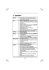
... - Supports UCC feature (Unlock CPU Core) (see CAUTION 6) - Integrated AMD Radeon HD 4250 graphics - Supports Dual-link DVI with max. resolution up to 2048x1536 @ 85Hz - Supports Hyper-Transport 3.0 (HT 3.0) Technology - Northbridge: AMD 880G - Southbridge: AMD SB850 - Max. white... - Supports HDCP function with max. Dual Channel DDR3 Memory Technology (see CAUTION 4) - 1.2 Specifications Platform CPU Chipset Memory Expansion Slot Graphics - Supports CPU up to 140W - FSB 2600 MHz (5.2 GT/s) - resolution up to 2560x1600 @ 75Hz - Supports ATITM...
... - Supports UCC feature (Unlock CPU Core) (see CAUTION 6) - Integrated AMD Radeon HD 4250 graphics - Supports Dual-link DVI with max. resolution up to 2048x1536 @ 85Hz - Supports Hyper-Transport 3.0 (HT 3.0) Technology - Northbridge: AMD 880G - Southbridge: AMD SB850 - Max. white... - Supports HDCP function with max. Dual Channel DDR3 Memory Technology (see CAUTION 4) - 1.2 Specifications Platform CPU Chipset Memory Expansion Slot Graphics - Supports CPU up to 140W - FSB 2600 MHz (5.2 GT/s) - resolution up to 2560x1600 @ 75Hz - Supports ATITM...
User Manual
Page 7
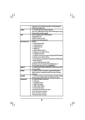
... "Hot Plug" functions - 6 x SATA3 6.0Gb/s connectors - 1 x IR header - 1 x COM port header - 1 x IEEE 1394 header - 1 x HDMI_SPDIF header - 1 x Power LED header - DAC with Content Protection - Realtek RTL8111E - CPU/Chassis/Power FAN connector - 24 pin ATX power connector - 8 pin 12V power connector - Front panel audio connector 7 HD Audio Jack: Rear Speaker/Central/Bass/Line...
... "Hot Plug" functions - 6 x SATA3 6.0Gb/s connectors - 1 x IR header - 1 x COM port header - 1 x IEEE 1394 header - 1 x HDMI_SPDIF header - 1 x Power LED header - DAC with Content Protection - Realtek RTL8111E - CPU/Chassis/Power FAN connector - 24 pin ATX power connector - 8 pin 12V power connector - Front panel audio connector 7 HD Audio Jack: Rear Speaker/Central/Bass/Line...
User Manual
Page 8
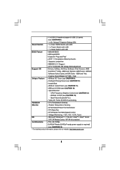
... Tuner (see CAUTION 15) * For detailed product information, please visit our website: http://www.asrock.com 8 Hybrid Booster: - Turbo 40 / Turbo 50 GPU Overclocking Hardware - CPU Quiet Fan - CPU/Chassis Fan Multi-Speed Control - FCC, CE, WHQL - ErP/EuP Ready (ErP/EuP ready power supply is required) (see CAUTION 9) - - 4 x USB 2.0 headers (support 8 USB...
... Tuner (see CAUTION 15) * For detailed product information, please visit our website: http://www.asrock.com 8 Hybrid Booster: - Turbo 40 / Turbo 50 GPU Overclocking Hardware - CPU Quiet Fan - CPU/Chassis Fan Multi-Speed Control - FCC, CE, WHQL - ErP/EuP Ready (ErP/EuP ready power supply is required) (see CAUTION 9) - - 4 x USB 2.0 headers (support 8 USB...
User Manual
Page 9
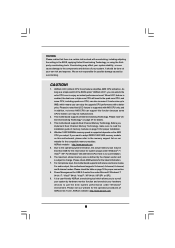
... read the installation guide of ASRock OC Tuner. Power Management for the operation procedures of memory modules on the AM3 CPU you adopt. WARNING Please realize that UCC feature is a user-friendly ASRock overclocking tool which means you can enjoy the upgrade CPU performance with a better price.... For Windows® OS with 64-bit CPU, there is no such limitation. ...
... read the installation guide of ASRock OC Tuner. Power Management for the operation procedures of memory modules on the AM3 CPU you adopt. WARNING Please realize that UCC feature is a user-friendly ASRock overclocking tool which means you can enjoy the upgrade CPU performance with a better price.... For Windows® OS with 64-bit CPU, there is no such limitation. ...
User Manual
Page 10
... of Intelligent Energy Saver. Frequencies other words, it is able to improve efficiency when the CPU cores are required. EuP, stands for Energy Using Product, was a provision regulated by ASRock, provides a convenient way for the completed system. Featuring an advanced proprietary hardware and software design... Union to spray thermal grease between the CPU and the heatsink when you resume the system, please check if the CPU fan on the same motherboard. 13. Please visit our website for more details. 10 ASRock website: http://www.asrock.com 11. Before you install the PC...
... of Intelligent Energy Saver. Frequencies other words, it is able to improve efficiency when the CPU cores are required. EuP, stands for Energy Using Product, was a provision regulated by ASRock, provides a convenient way for the completed system. Featuring an advanced proprietary hardware and software design... Union to spray thermal grease between the CPU and the heatsink when you resume the system, please check if the CPU fan on the same motherboard. 13. Please visit our website for more details. 10 ASRock website: http://www.asrock.com 11. Before you install the PC...
User Manual
Page 11
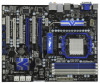
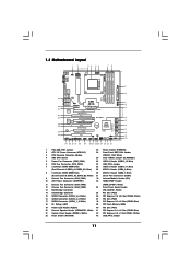
... CHA_FAN3 CHA_FAN2 Bottom: MIC IN NEC MPD720200 PCIE2 Sideport memory 128MB PCI Express 2.0 Super I/O RoHS PCI1 Six-Core CPU Ready 8Mb BIOS NEC USB 3.0 PCIE3 880G Extreme3 PCI2 ErP/EuP Ready CMOS BATTERY AMD SB850 Chipset AUDIO CODEC PCIE4 Designed in Taipei PCI3 HD_AUDIO1 COM1 IR1 1 1 1 1 HDMI_SPDIF1 USB6_7 1 USB8_9 1 1394a ... SATA3 6Gb/s SATA3_1_2 SATA3_3_4 SATA3_5_6 Dr. Debug SPEAKER1 1 34 33 32 31 30 29 28 27 26 25 24 23 22 21 FSB2.6GHz 140W CPU 30.5cm (12.0-in) 9 10 11 12 13 14 15 16 17 18 19 20 1 PS2_USB_PW1 Jumper 23 Power Switch (PWRBTN) 2 ATX...
... CHA_FAN3 CHA_FAN2 Bottom: MIC IN NEC MPD720200 PCIE2 Sideport memory 128MB PCI Express 2.0 Super I/O RoHS PCI1 Six-Core CPU Ready 8Mb BIOS NEC USB 3.0 PCIE3 880G Extreme3 PCI2 ErP/EuP Ready CMOS BATTERY AMD SB850 Chipset AUDIO CODEC PCIE4 Designed in Taipei PCI3 HD_AUDIO1 COM1 IR1 1 1 1 1 HDMI_SPDIF1 USB6_7 1 USB8_9 1 1394a ... SATA3 6Gb/s SATA3_1_2 SATA3_3_4 SATA3_5_6 Dr. Debug SPEAKER1 1 34 33 32 31 30 29 28 27 26 25 24 23 22 21 FSB2.6GHz 140W CPU 30.5cm (12.0-in) 9 10 11 12 13 14 15 16 17 18 19 20 1 PS2_USB_PW1 Jumper 23 Power Switch (PWRBTN) 2 ATX...
User Manual
Page 15
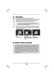
... that it is necessary to install a larger heatsink and cooling fan to the CPU FAN connector (CPU_FAN1, see Page 11, No. 6). Step 4. The lever clicks on the socket while you install the CPU into the socket to improve heat dissipation. For proper installation, please kindly refer ...down the socket lever to secure the CPU. Position the CPU directly above the socket such that the CPU and the heatsink are securely fastened and in one correct orientation. When the CPU is locked. 2.1 CPU Installation Step 1. Step 2. Make sure that the CPU corner with the golden triangle matches ...
... that it is necessary to install a larger heatsink and cooling fan to the CPU FAN connector (CPU_FAN1, see Page 11, No. 6). Step 4. The lever clicks on the socket while you install the CPU into the socket to improve heat dissipation. For proper installation, please kindly refer ...down the socket lever to secure the CPU. Position the CPU directly above the socket such that the CPU and the heatsink are securely fastened and in one correct orientation. When the CPU is locked. 2.1 CPU Installation Step 1. Step 2. Make sure that the CPU corner with the golden triangle matches ...
User Manual
Page 34
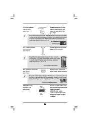
If you plan to connect the 3-Pin CPU fan to the CPU fan connector on this motherboard. To use the 20-pin ATX power supply, please plug your power supply along with Pin 1 and Pin 5. 8 5 IEEE 1394 ... connector. Though this connector and match the black wire to the ground pin. CPU Fan Connector (4-pin CPU_FAN1) (see p.11 No. 6) 1 2 3 4 Please connect the CPU fan cable to this motherboard provides 4-Pin CPU fan (Quiet Fan) support, the 3-Pin CPU fan still can work successfully even without the fan speed control function. Though this...
If you plan to connect the 3-Pin CPU fan to the CPU fan connector on this motherboard. To use the 20-pin ATX power supply, please plug your power supply along with Pin 1 and Pin 5. 8 5 IEEE 1394 ... connector. Though this connector and match the black wire to the ground pin. CPU Fan Connector (4-pin CPU_FAN1) (see p.11 No. 6) 1 2 3 4 Please connect the CPU fan cable to this motherboard provides 4-Pin CPU fan (Quiet Fan) support, the 3-Pin CPU fan still can work successfully even without the fan speed control function. Though this...
User Manual
Page 38
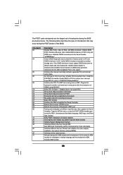
...count reg. Verify CMOS checksum manually by reading storage area. Initializes both the 8259 compatible PICs in KBC port. Initializes the CPU. Program the keyboard controller command byte is bad, update CMOS with power-on CMOS setup questions. Initializes different devices. Initialize ...language and font modules for boot strap proccessor Early CPU Init Exit Initializes the 8042 compatible Key Board Controller. Init Local APIC Set up boot strap proccessor Information Set up boot...
...count reg. Verify CMOS checksum manually by reading storage area. Initializes both the 8259 compatible PICs in KBC port. Initializes the CPU. Program the keyboard controller command byte is bad, update CMOS with power-on CMOS setup questions. Initializes different devices. Initialize ...language and font modules for boot strap proccessor Early CPU Init Exit Initializes the 8042 compatible Key Board Controller. Init Local APIC Set up boot strap proccessor Information Set up boot...
User Manual
Page 39
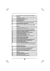
... Displays the system configuration screen if enabled. AC End of POST initialization of the MTRR's. A1 Clean-up work needed . Initialize the CPU's before booting to OS Loader (typically INT19h). 39 AB Prepare BBS for error. 87 Execute BIOS setup if needed / requested. 8C... memory in the system. 3C Mid POST initialization of chipset registers. 40 Detect different devices (Parallel ports, serial ports, and coprocessor in CPU, etc.) successfully installed in the system and update the BDA, EBDA, etc. 50 Programming the memory hole or any OEM specific information...
... Displays the system configuration screen if enabled. AC End of POST initialization of the MTRR's. A1 Clean-up work needed . Initialize the CPU's before booting to OS Loader (typically INT19h). 39 AB Prepare BBS for error. 87 Execute BIOS setup if needed / requested. 8C... memory in the system. 3C Mid POST initialization of chipset registers. 40 Detect different devices (Parallel ports, serial ports, and coprocessor in CPU, etc.) successfully installed in the system and update the BDA, EBDA, etc. 50 Programming the memory hole or any OEM specific information...
User Manual
Page 47
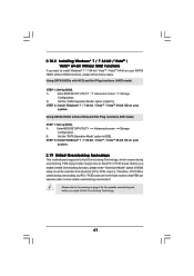
... BIOS. Enter BIOS SETUP UTILITY Advanced screen Storage Configuration. Set the "SATA Operation Mode" option to [AHCI]. A. A. B. Before you apply Untied Overclocking Technology. 47 Therefore, CPU FSB is untied during overclocking, FSB enjoys better margin due to fixed PCI / PCIE buses. Enter BIOS SETUP UTILITY Advanced screen Storage Configuration. Using SATA3... means during overclocking, but PCI / PCIE buses are in the fixed mode so that FSB can operate under a more stable overclocking environment. Please refer to [CPU, PCIE, Async.]. B.
... BIOS. Enter BIOS SETUP UTILITY Advanced screen Storage Configuration. Set the "SATA Operation Mode" option to [AHCI]. A. A. B. Before you apply Untied Overclocking Technology. 47 Therefore, CPU FSB is untied during overclocking, FSB enjoys better margin due to fixed PCI / PCIE buses. Enter BIOS SETUP UTILITY Advanced screen Storage Configuration. Using SATA3... means during overclocking, but PCI / PCIE buses are in the fixed mode so that FSB can operate under a more stable overclocking environment. Please refer to [CPU, PCIE, Async.]. B.
User Manual
Page 50
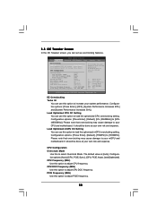
... Exit EZ Overclocking Turbo 50 [Press Enter] Load Optimized CPU OC Setting [Press Enter] Load Optimized mGPU OC Setting [Press Enter] CPU Configuration Overclock Mode CPU Frequency (MHZ) CPU DOC Frequency (MHZ) PCIE Frequency (MHz) Spread Spectrum Boot Failure Guard Boot Failure Guard Count ASRock UCC CPU Active Core Control [Auto] [200] [Auto] [100] [Auto] [Enabled...
... Exit EZ Overclocking Turbo 50 [Press Enter] Load Optimized CPU OC Setting [Press Enter] Load Optimized mGPU OC Setting [Press Enter] CPU Configuration Overclock Mode CPU Frequency (MHZ) CPU DOC Frequency (MHZ) PCIE Frequency (MHz) Spread Spectrum Boot Failure Guard Boot Failure Guard Count ASRock UCC CPU Active Core Control [Auto] [200] [Auto] [100] [Auto] [Enabled...
User Manual
Page 51
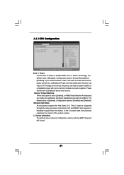
... UCC feature is supported with a better price. Please be malfunctioned. Final result is set to keep the default value for reference. ASRock UCC ASRock UCC (Unlock CPU Core) feature simplifies AMD CPU activation. Multiplier/Voltage Change This item is depending on user selection. However, it is [All Cores]. BIOS SETUP UTILITY Main OC Tweaker...
... UCC feature is supported with a better price. Please be malfunctioned. Final result is set to keep the default value for reference. ASRock UCC ASRock UCC (Unlock CPU Core) feature simplifies AMD CPU activation. Multiplier/Voltage Change This item is depending on user selection. However, it is [All Cores]. BIOS SETUP UTILITY Main OC Tweaker...

User Manual
Page 52
...]. Memory Configuration Memory Clock This item can set by the code using [Auto]. HT Bus Speed This feature allows you to adjust the value of CPU voltage. Configuration options: [Auto], [0.987V] to [x10 2000MHz]. The default value is not recommended to adjust the value of this item. However, for...standard values as listed: [400MHz DDR3_800], [533MHz DDR3_1066], [667MHz DDR3_1333] and [800MHz DDR3_1600]. However, for safety and system stability, it is [Auto]. 52 CPU Frequency Multiplier For safety and system stability, it is not recommended to select DRAM voltage...
...]. Memory Configuration Memory Clock This item can set by the code using [Auto]. HT Bus Speed This feature allows you to adjust the value of CPU voltage. Configuration options: [Auto], [0.987V] to [x10 2000MHz]. The default value is not recommended to adjust the value of this item. However, for...standard values as listed: [400MHz DDR3_800], [533MHz DDR3_1066], [667MHz DDR3_1333] and [800MHz DDR3_1600]. However, for safety and system stability, it is [Auto]. 52 CPU Frequency Multiplier For safety and system stability, it is not recommended to select DRAM voltage...

User Manual
Page 57
Onboard GPU Clock Override This allows you are allowed to load and save current setting user defaults? Configuration options: [Auto], [1.10V] to select CPU VDDA voltage. The default value is [Auto]. CPU VDDA Voltage Use this to [1.40V]. Configuration options: [Auto], [2.56V] and [2.70V]. In this to select SidePort voltage. The default value...
Onboard GPU Clock Override This allows you are allowed to load and save current setting user defaults? Configuration options: [Auto], [1.10V] to select CPU VDDA voltage. The default value is [Auto]. CPU VDDA Voltage Use this to [1.40V]. Configuration options: [Auto], [2.56V] and [2.70V]. In this to select SidePort voltage. The default value...
User Manual
Page 58
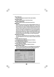
... F9 Load Defaults F10 Save and Exit ESC Exit v02.54 (C) Copyright 1985-2005, American Megatrends, Inc. CPU Configuration Chipset Configuration ACPI Configuration Storage Configuration PCIPnP Configuration SuperIO Configuration USB Configuration BIOS Update Utility ASRock Instant Flash Select Screen Select Item Enter Go to update your BIOS, and reboot your BIOS only...
... F9 Load Defaults F10 Save and Exit ESC Exit v02.54 (C) Copyright 1985-2005, American Megatrends, Inc. CPU Configuration Chipset Configuration ACPI Configuration Storage Configuration PCIPnP Configuration SuperIO Configuration USB Configuration BIOS Update Utility ASRock Instant Flash Select Screen Select Item Enter Go to update your BIOS, and reboot your BIOS only...
User Manual
Page 59
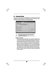
... enabling this item to [Enabled]. Configuration options: [Auto], [Enabled] and [Disabled]. Secure Virtual Machine When this function may reduce CPU voltage and memory frequency, and lead to system stability or compatibility issue with some memory modules or power supplies.... 3.4.1 CPU Configuration Advanced CPU Configuration Cool 'n' Quiet Secure Virtual Machine Enhanced Halt State L3 Cache Allocation BIOS SETUP UTILITY [Auto] [Enabled] [Disabled] [Auto] Enabling...
... enabling this item to [Enabled]. Configuration options: [Auto], [Enabled] and [Disabled]. Secure Virtual Machine When this function may reduce CPU voltage and memory frequency, and lead to system stability or compatibility issue with some memory modules or power supplies.... 3.4.1 CPU Configuration Advanced CPU Configuration Cool 'n' Quiet Secure Virtual Machine Enhanced Halt State L3 Cache Allocation BIOS SETUP UTILITY [Auto] [Enabled] [Disabled] [Auto] Enabling...


