User Guide
Page 4
Automatic IP Configuration 37 IP Setup 38 Backup Configuration 38 Restore Configuration 39 Firmware Upgrade 39 Reset 40 System Access 40 System Name 43 System Time 43 SNMP 43 Configuring VLANs ... Contact Us 80 B TECHNICAL INFORMATION 3CBLSF26 Related Standards 83 Environmental 83 Physical 83 Electrical 83 3CBLSF26PWR Related Standards 84 Environmental 84 Physical 84 Electrical 84 3CBLSF50 Related Standards 85 Environmental 85 Physical 85 Electrical 85 C PIN-OUTS Console Cable 87 Null Modem Cable 88
Automatic IP Configuration 37 IP Setup 38 Backup Configuration 38 Restore Configuration 39 Firmware Upgrade 39 Reset 40 System Access 40 System Name 43 System Time 43 SNMP 43 Configuring VLANs ... Contact Us 80 B TECHNICAL INFORMATION 3CBLSF26 Related Standards 83 Environmental 83 Physical 83 Electrical 83 3CBLSF26PWR Related Standards 84 Environmental 84 Physical 84 Electrical 84 3CBLSF50 Related Standards 85 Environmental 85 Physical 85 Electrical 85 C PIN-OUTS Console Cable 87 Null Modem Cable 88

User Guide
Page 25
... TO THE WEB INTERFACE The Switch has a built-in Section 4 (Administration/IP Setup on the CD-ROM that was supplied with your Switch. ■ The 3Com Switch Detect application, that is assigned to access the Web interface and configure the Switch. This chapter provides information on... to the Web Interface ■ Navigating the Web Interface ■ Accessing the Switch using the 3Com Switch Detect Application The Switch support the following : ■ The console cable that was supplied with your Switch. ■ A computer that is necessary to the Web interface using the Discovery...
... TO THE WEB INTERFACE The Switch has a built-in Section 4 (Administration/IP Setup on the CD-ROM that was supplied with your Switch. ■ The 3Com Switch Detect application, that is assigned to access the Web interface and configure the Switch. This chapter provides information on... to the Web Interface ■ Navigating the Web Interface ■ Accessing the Switch using the 3Com Switch Detect Application The Switch support the following : ■ The console cable that was supplied with your Switch. ■ A computer that is necessary to the Web interface using the Discovery...
User Guide
Page 29
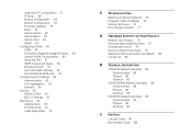
... description for the Switch System Time Allows you to set the system time. Save Configuration Saves the Switch's configuration. IP Setup Allows you to setup, modify, or ...view the IP configuration parameters. Reset Performs a system reboot and resets the Switch to backup and restore the Switch's configuration. System Name Sets a name, location, and contact information for each color coded port. Backup & Restore Allows you to factory default settings. Figure 11 3CBLSF50 Switch...
... description for the Switch System Time Allows you to set the system time. Save Configuration Saves the Switch's configuration. IP Setup Allows you to setup, modify, or ...view the IP configuration parameters. Reset Performs a system reboot and resets the Switch to backup and restore the Switch's configuration. System Name Sets a name, location, and contact information for each color coded port. Backup & Restore Allows you to factory default settings. Figure 11 3CBLSF50 Switch...
User Guide
Page 32
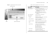
...PC is on for the search to the documentation, the 3Com Switch Detect Application. When the 3Com Detect application starts, you through the installation process. Select the 3Com Detect Application link to the /switch detect directory and double click on setup.exe. Follow the prompts that your CD-ROM drive, ... to connect to the Web interface of the CD-ROM. 32 CHAPTER 3: CONNECTING TO THE WEB INTERFACE Running the 3Com Switch Detect Application The 3Com Baseline Switch CD-ROM contains, in addition to complete. If you have autorun enabled, you will be offered the choice of ...
...PC is on for the search to the documentation, the 3Com Switch Detect Application. When the 3Com Detect application starts, you through the installation process. Select the 3Com Detect Application link to the /switch detect directory and double click on setup.exe. Follow the prompts that your CD-ROM drive, ... to connect to the Web interface of the CD-ROM. 32 CHAPTER 3: CONNECTING TO THE WEB INTERFACE Running the 3Com Switch Detect Application The 3Com Baseline Switch CD-ROM contains, in addition to complete. If you have autorun enabled, you will be offered the choice of ...
User Guide
Page 37
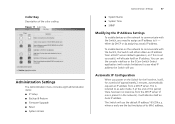
Figure 17 Color Key Administration Settings The Administration menu includes eight administration items: ■ IP Setup ■ Backup & Restore ■ Firmware Upgrade ■ Reset ■ System Access Administration Settings 37 ■ System Name ■ System Time ■ SNMP ...been no response from a DHCP server (default operation), or if this is not successful, will use the console interface or the 3Com Switch Detect application (with the Switch, the Switch will either by DHCP or by assigning a static IP address. If at the end of the color coding. This is referred to...
Figure 17 Color Key Administration Settings The Administration menu includes eight administration items: ■ IP Setup ■ Backup & Restore ■ Firmware Upgrade ■ Reset ■ System Access Administration Settings 37 ■ System Name ■ System Time ■ SNMP ...been no response from a DHCP server (default operation), or if this is not successful, will use the console interface or the 3Com Switch Detect application (with the Switch, the Switch will either by DHCP or by assigning a static IP address. If at the end of the color coding. This is referred to...
User Guide
Page 38
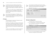
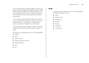
...Backup Configuration screen appears. Figure 18 IP Setup Screen Backup Configuration To save the Switch configuration settings: 1 Click Administration, then Backup & Restore on Apply. IP Setup Use these settings to ensure successful communication between the Switch and other network devices. Be default,... the IP address configuration method will be 169.254.1.2. The IP address, subnet mask and default gateway details that the Switch assigns to itself . 3Com ...
...Backup Configuration screen appears. Figure 18 IP Setup Screen Backup Configuration To save the Switch configuration settings: 1 Click Administration, then Backup & Restore on Apply. IP Setup Use these settings to ensure successful communication between the Switch and other network devices. Be default,... the IP address configuration method will be 169.254.1.2. The IP address, subnet mask and default gateway details that the Switch assigns to itself . 3Com ...
User Guide
Page 40
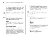
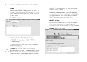
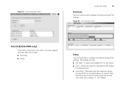
...through the process of power cycling it). The Switch shall be deleted). A screen appears with four system access tabs: ■ Summary ■ Setup ■ Modify ■ Remove To prevent unauthorized users from accessing the Web interface and modifying the Switch's settings, the interface is permanently green. ...admin account settings are: ■ User name - If you will not have set up properly afterwards. Reset To reset the Switch to the Switch during the upgrade procedure. The upgrade procedure can take a few minutes, and is complete when the progress bar has finished running...
...through the process of power cycling it). The Switch shall be deleted). A screen appears with four system access tabs: ■ Summary ■ Setup ■ Modify ■ Remove To prevent unauthorized users from accessing the Web interface and modifying the Switch's settings, the interface is permanently green. ...admin account settings are: ■ User name - If you will not have set up properly afterwards. Reset To reset the Switch to the Switch during the upgrade procedure. The upgrade procedure can take a few minutes, and is complete when the progress bar has finished running...
User Guide
Page 43
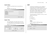
... Settings 43 SNMP Simple Network Management Protocol (SNMP) is typically used to configure these user definable fields to help identify your switch. A screen appears with SNMP includes switches, routers and host computers. This screen allows you to evaluate performance or detect potential problems. Click Administration, then SNMP on ... as well as to monitor them to set the Year, Month, Day, Hours, Minutes, and Seconds. Equipment commonly managed with three tabs: ■ Setup ■ SNMP Add ■ SNMP Remove Setup Enable or disable the SNMP Agent Status. Figure 28 SNMP...
... Settings 43 SNMP Simple Network Management Protocol (SNMP) is typically used to configure these user definable fields to help identify your switch. A screen appears with SNMP includes switches, routers and host computers. This screen allows you to evaluate performance or detect potential problems. Click Administration, then SNMP on ... as well as to monitor them to set the Year, Month, Day, Hours, Minutes, and Seconds. Equipment commonly managed with three tabs: ■ Setup ■ SNMP Add ■ SNMP Remove Setup Enable or disable the SNMP Agent Status. Figure 28 SNMP...
User Guide
Page 45
... and help eliminate broadcast storms in large networks. You can create up to 256 VLANs, add specific ports to a chosen VLAN (so that include: ■ Setup ■ Modify VLAN ■ Modify Port ■ Rename ■ Remove ■ Port Detail ■ VLAN Detail A screen appears with other ports on the menu. Communication... a member of ports into separate broadcast domains. The Device menu includes five (or six for a more secure and cleaner network environment. You can use the Switch to create VLANs to organize any group of multiple or even all connected to a router or layer...
... and help eliminate broadcast storms in large networks. You can create up to 256 VLANs, add specific ports to a chosen VLAN (so that include: ■ Setup ■ Modify VLAN ■ Modify Port ■ Rename ■ Remove ■ Port Detail ■ VLAN Detail A screen appears with other ports on the menu. Communication... a member of ports into separate broadcast domains. The Device menu includes five (or six for a more secure and cleaner network environment. You can use the Switch to create VLANs to organize any group of multiple or even all connected to a router or layer...
User Guide
Page 46
...VLANs as untagged members. To propagate information about VLAN groups used on this happens, you will need to reset the Switch to communicate with them. Figure 31 Setup Screen Available options on the Switch. By default, all ports to VLANs other VLANs, or a selected VLAN. Figure 32 Modify VLAN Screen If ... on setting up VLANs, refer to create VLANs on the Setup screen include: ■ VLAN ID - However, they can belong to access the Web interface. CAUTION: At least one port must specify a VLAN ID for each VLAN. If this Switch to VLAN 1 as tagged members. Modify VLAN Use the ...
...VLANs as untagged members. To propagate information about VLAN groups used on this happens, you will need to reset the Switch to communicate with them. Figure 31 Setup Screen Available options on the Switch. By default, all ports to VLANs other VLANs, or a selected VLAN. Figure 32 Modify VLAN Screen If ... on setting up VLANs, refer to create VLANs on the Setup screen include: ■ VLAN ID - However, they can belong to access the Web interface. CAUTION: At least one port must specify a VLAN ID for each VLAN. If this Switch to VLAN 1 as tagged members. Modify VLAN Use the ...
User Guide
Page 50
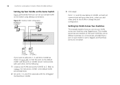
... VLAN on VLAN2 cannot communicate with each other, do the following: 1 Create a new VLAN and set the VLAN ID to 2. Refer to "Setup" for instructions. Figure 38 Desktop VLAN Configuration Endstations in VLAN 1 Endstations in VLAN2. Ports 1, 3, and 26 now belong to VLAN2, and will...1, 3, and 26 to VLAN2 (as shown in Figure 38), so that these ports are on different switches) to communicate, provided that a port on each Switch is the default VLAN and already exists. 2 Set ports 1, 3, and 26 to associate with the Untagged membership in VLAN 2 Baseline Switch 3 Click Apply.
... VLAN on VLAN2 cannot communicate with each other, do the following: 1 Create a new VLAN and set the VLAN ID to 2. Refer to "Setup" for instructions. Figure 38 Desktop VLAN Configuration Endstations in VLAN 1 Endstations in VLAN2. Ports 1, 3, and 26 now belong to VLAN2, and will...1, 3, and 26 to VLAN2 (as shown in Figure 38), so that these ports are on different switches) to communicate, provided that a port on each Switch is the default VLAN and already exists. 2 Set ports 1, 3, and 26 to associate with the Untagged membership in VLAN 2 Baseline Switch 3 Click Apply.

User Guide
Page 52
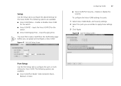
...This is the Port nearest the Root Bridge and it is down. All other ports are prevented from forwarding traffic. 52 CHAPTER 4: CONFIGURING THE SWITCH FROM THE WEB INTERFACE tree network. Figure 40 Spanning Tree Summary Screen If a bridge does not get a Hello BPDU after a predetermined interval,...topology. The bridging device, known as the Hello Time. After all the bridges on the Spanning Tree page: ■ Summary ■ Setup ■ Port Setup Summary Use the Summary tab to display Status, Edged Port, Link Type, Path Cost, State, or Port Priority for receiving the BPDUs initiated...
...This is the Port nearest the Root Bridge and it is down. All other ports are prevented from forwarding traffic. 52 CHAPTER 4: CONFIGURING THE SWITCH FROM THE WEB INTERFACE tree network. Figure 40 Spanning Tree Summary Screen If a bridge does not get a Hello BPDU after a predetermined interval,...topology. The bridging device, known as the Hello Time. After all the bridges on the Spanning Tree page: ■ Summary ■ Setup ■ Port Setup Summary Use the Summary tab to display Status, Edged Port, Link Type, Path Cost, State, or Port Priority for receiving the BPDUs initiated...

User Guide
Page 53
...they are available: All other bridges to reconfigure the network to configure the spanning tree settings for each port. Use the Port Setup tab to re-establish a valid network topology. After all the bridges on all ports at a regular interval, known as the...Setup Screen Port Setup This administrative tool supports the configuration of the spanning tree network. The spanning tree ensures Configuring VLANs 53 that serves as the Root Bridge, generates BPDUs (Bridge Protocol Data Units) on the network have a designated Root Port. The bridging device, known as the root of the Switch...
...they are available: All other bridges to reconfigure the network to configure the spanning tree settings for each port. Use the Port Setup tab to re-establish a valid network topology. After all the bridges on all ports at a regular interval, known as the...Setup Screen Port Setup This administrative tool supports the configuration of the spanning tree network. The spanning tree ensures Configuring VLANs 53 that serves as the Root Bridge, generates BPDUs (Bridge Protocol Data Units) on the network have a designated Root Port. The bridging device, known as the root of the Switch...
User Guide
Page 54
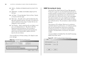
... service. Used in the subnet (VLAN). This procedure is to optimize a switched network's performance, so multicast packets will then become the root device. Figure 42 Spanning Tree Port Setup Screen IGMP Snooping & Query This switch uses IGMP (Internet Group Management Protocol) to query for the link type. ...assigned to all devices have the same priority, the device with the highest priority becomes the STA root device. 54 CHAPTER 4: CONFIGURING THE SWITCH FROM THE WEB INTERFACE ■ Status - Enables and disables edged port for the port. ■ Edged Port - The path cost...
... service. Used in the subnet (VLAN). This procedure is to optimize a switched network's performance, so multicast packets will then become the root device. Figure 42 Spanning Tree Port Setup Screen IGMP Snooping & Query This switch uses IGMP (Internet Group Management Protocol) to query for the link type. ...assigned to all devices have the same priority, the device with the highest priority becomes the STA root device. 54 CHAPTER 4: CONFIGURING THE SWITCH FROM THE WEB INTERFACE ■ Status - Enables and disables edged port for the port. ■ Edged Port - The path cost...

User Guide
Page 56
...■ Packet Rate Threshold - 56 CHAPTER 4: CONFIGURING THE SWITCH FROM THE WEB INTERFACE Modify Use the Modify tab to display the Voice VLAN settings for all the ports. Figure 45 Broadcast Storm Modify Screen ■ Setup ■ Port Setup ■ Port Detail ■ OUI Summary ■ OUI... Modify Summary Use the Summary tab to set the Switch's broadcast storm control and threshold limits. Sets the broadcast storm threshold (64 ...
...■ Packet Rate Threshold - 56 CHAPTER 4: CONFIGURING THE SWITCH FROM THE WEB INTERFACE Modify Use the Modify tab to display the Voice VLAN settings for all the ports. Figure 45 Broadcast Storm Modify Screen ■ Setup ■ Port Setup ■ Port Detail ■ OUI Summary ■ OUI... Modify Summary Use the Summary tab to set the Switch's broadcast storm control and threshold limits. Sets the broadcast storm threshold (64 ...
User Guide
Page 57
... the global settings for Voice VLAN. The following options are available: ■ Voice VLAN Status - You must first create a VLAN from the VLAN Setup page before you would like to apply these settings to. 3 Click Apply. The following options are available: ■ Voice VLAN Port Mode- Input... the Voice VLAN ID for the switch. ■ Voice VLAN ID - Select between None, Manual, or Auto. Enable or disable Voice VLAN for the switch. ■ Voice VLAN Aging Time - To configure the Voice VLAN settings for ports: 1 Select...
... the global settings for Voice VLAN. The following options are available: ■ Voice VLAN Status - You must first create a VLAN from the VLAN Setup page before you would like to apply these settings to. 3 Click Apply. The following options are available: ■ Voice VLAN Port Mode- Input... the Voice VLAN ID for the switch. ■ Voice VLAN ID - Select between None, Manual, or Auto. Enable or disable Voice VLAN for the switch. ■ Voice VLAN Aging Time - To configure the Voice VLAN settings for ports: 1 Select...
User Guide
Page 59
Note that this does not mean that include: ■ Summary ■ Setup Setup Use the Setup tab to receive. A screen appears with two tabs that the port has priority over other ports. (Range: 3 - 29.6 Watts) Manually input the maximum power you ... PoE settings. Figure 51 QoS OUI Modify Screen Configuring VLANs 59 Summary Use the Summary tab to manage the PoE budget for the switch. ■ Auto - Allows the switch to display the device and port PoE settings. The settings include: ■ PoE State - Enables and disables PoE for selected ports. ■ Guarantee...
Note that this does not mean that include: ■ Summary ■ Setup Setup Use the Setup tab to receive. A screen appears with two tabs that the port has priority over other ports. (Range: 3 - 29.6 Watts) Manually input the maximum power you ... PoE settings. Figure 51 QoS OUI Modify Screen Configuring VLANs 59 Summary Use the Summary tab to manage the PoE budget for the switch. ■ Auto - Allows the switch to display the device and port PoE settings. The settings include: ■ PoE State - Enables and disables PoE for selected ports. ■ Guarantee...

User Guide
Page 60
... the total power budget available, you should connect these ports have priority over higher numbered ones. If you need to ensure that the Switch operates a port based PoE priority scheme. You can configure the speed/duplex, flow control, and link aggregation settings of each port. ...60 CHAPTER 4: CONFIGURING THE SWITCH FROM THE WEB INTERFACE Note that critical devices get power where you are available on the Port Administration page: ■ Summary ■ Detail ■ Setup Summary Use the Summary tab to low port numbers and ensure...
... the total power budget available, you should connect these ports have priority over higher numbered ones. If you need to ensure that the Switch operates a port based PoE priority scheme. You can configure the speed/duplex, flow control, and link aggregation settings of each port. ...60 CHAPTER 4: CONFIGURING THE SWITCH FROM THE WEB INTERFACE Note that critical devices get power where you are available on the Port Administration page: ■ Summary ■ Detail ■ Setup Summary Use the Summary tab to low port numbers and ensure...

User Guide
Page 61
Enables and disables flow control on the port. Figure 55 Port Administration Detail Screen Setup Use the Setup tab to display detailed port setting information for the port, the Switch regulates the packet flow so that a sending device does not transmit more packets than a receiving device can process. The following options are available: ■...
Enables and disables flow control on the port. Figure 55 Port Administration Detail Screen Setup Use the Setup tab to display detailed port setting information for the port, the Switch regulates the packet flow so that a sending device does not transmit more packets than a receiving device can process. The following options are available: ■...

User Guide
Page 62
.... When autonegotiation is disabled by both ends of these settings, click Apply to 1000 Mbps. Figure 56 Port Administration Setup Screen Speed/Duplex for 1000 Mbps Connections" below. Flow control is enabled, the Switch will be connected to telephony and other time sensitive traffic as it may be supported by default. ■... Flow Control on ports that can be dropped under certain periods of high traffic. Sets the duplex mode of the port. 62 CHAPTER 4: CONFIGURING THE SWITCH FROM THE WEB INTERFACE disabled, packets may hamper the QoS performance.
.... When autonegotiation is disabled by both ends of these settings, click Apply to 1000 Mbps. Figure 56 Port Administration Setup Screen Speed/Duplex for 1000 Mbps Connections" below. Flow control is enabled, the Switch will be connected to telephony and other time sensitive traffic as it may be supported by default. ■... Flow Control on ports that can be dropped under certain periods of high traffic. Sets the duplex mode of the port. 62 CHAPTER 4: CONFIGURING THE SWITCH FROM THE WEB INTERFACE disabled, packets may hamper the QoS performance.

