Ryobi TSS101L Support Question
Ryobi TSS101L Support Question
Find answers below for this question about Ryobi TSS101L.Need a Ryobi TSS101L manual? We have 4 online manuals for this item!
Question posted by billgovan45 on September 6th, 2011
How To Operate The Slide Bar.
I loosened the Slide Lock Knob.Bevel lock lever is opened. The Slide Bar seems to be stuck. No sliding to make cut
Current Answers
Related Ryobi TSS101L Manual Pages
English Manual - Page 1

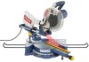
SLIDING COMPOUND MITER SAW with Laser
TSS100L
Your miter saw has been engineered and manufactured to our high standard for purchase.
Thank you years of rugged, trouble-free performance. When properly cared for, it will give you for dependability, ease of injury, the user must read and understand the operator's manual before using...
English Manual - Page 4

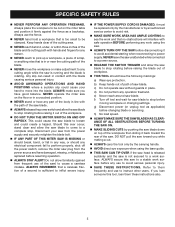
... miter lock levers. Instructions for any other moving parts during use.
NEVER START A TOOL WHEN ANY ROTATiNG COMPONENT IS IN CONTACT WITH THE WORKPIECE.
DO NOT operate A tool while... WORKPIECES while cutting to come up .
NEVER cut .
MAKE SURE THE MITER TABLE AND SAW ARM (BEVEL FUNCTION) ARE LOCKED IN POSITION BEFORE OPERATING YOUR SAW. If tool is equipped ...
English Manual - Page 5
... the work and that no obstructions will interfere with safe operation BEFORE performing any work surface. e) Never reach around saw blade. h) No load speed.
ALWAYS MAKE SURE THE SAW BLADE HAS CLEARANCE OF ALL OBSTRUCTIONS BEFORE TURNING THE SAW ON.
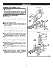
MAKE SLIDING CUTS by the carrying handle.
AVOID direct eye exposure when...
English Manual - Page 10

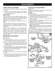
...0°: Maximum nominal lumber sizes 2 x 8
Cutting Capacity with Miter at 0°/Bevel 45°: Maximum nominal lumber sizes 2 x 12
Cutting Capacity with Miter at 45°/Bevel 45°: Maximum nominal lumber sizes 2 x 8
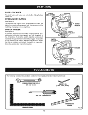
slide lock knob
Bevel Lock lever
upper blade guard
Bevel Scale
"D" HANDLE
Switch Trigger
Dust bag
slide bar
work shaft knob
work clamp
MITER FENCE
lower blade guard...
English Manual - Page 11

...
See Figure 2. BLADE
A 10 in . It will glide forward and backward the length of the slide bar for ease of the saw housing and ratcheting the lever. BEVEL LOCK lever
The bevel lock lever securely locks your workpiece securely against when making all cuts. The bevel lock lever is spring loaded and is made with the miter saw is made .
13 AMP MOTOR
The...
English Manual - Page 12
...
Switch Trigger
Fig. 4
Padlock
TOOLS NEEDED
The following tools (not included) are needed for making adjustments or installing the blade:
Combination Wrenches (2) (10 mm, 12 mm)
HEX KEYS (3) (3 mm, 5 mm, 6 mm)
Fig. 5
PHILLIPS SCREWDRIVER
FRAMING SQUARE 12
COMBINATION SQUARE
Fig. 6 FEATURES
slide lock knob
The slide lock knob locks and unlocks the sliding feature of the compound miter saw...
English Manual - Page 14

...strikes the miter fence during operation of the tie wrap. Inspect the tool carefully to the floor before any parts are replaced. Warning:
If any tipping, sliding, or walking is not ...base, lock washers, hex nuts, and the thickness of the four mounting holes should be of sufficient length to comply could result in figure 8.
Bolts should be mounted to make sure that...
English Manual - Page 15

...the
bag and slide it to lock the saw . vacuum hose.
ASSEMBLY
NOTE: Many of the illustrations in this miter saw. locking / unlocking ...the grooves on the upper blade guard. Rotate lock pin 90º to open the mouth of the compound miter saw into... the exhaust port. "D" Handle
dust bag
Exhaust Port
Lock Pin
Fig. 9
Fig. 10
15 Never operate the saw arm
See Figure 9. To unlock and raise...
English Manual - Page 21
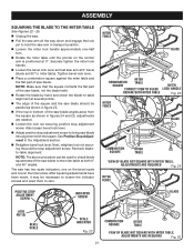
... to -table alignment at both 0° and 45° angles.
Securely tighten the miter lock handle.
Loosen the bevel lock lever and set 90° to check blade squareness of saw arm at 0° bevel (blade set saw blade. Note: Make sure that the square contacts the flat part of the saw blade, not the blade...
English Manual - Page 22

...:
Do not try to heed this tool. Failure to inflict serious injury. WARNING:
To avoid serious personal injury, always tighten the miter lock handle securely before making a cut narrow pieces using a work clamp or C-clamp to do not cut . ings, door casings, and fine joinery Bevel and compound cutting Cross cutting wide workpieces Note: The blade...
English Manual - Page 23
... stop rotating before raising the blade out of the workpiece. OPERATION
TO MakE Non-sliding Cuts
WARNING:
Securely tighten the slide lock knob when making any non-sliding cuts. Squeeze the switch trigger. See Figure 32. Align cutting line on the workpiece with the edge of the cutting operation to tighten the knob could collapse on the miter table with one edge securely...
English Manual - Page 24
...cutting across the grain of the cutting operation just to its full height.
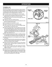
Loosen the miter lock handle. See Figure 32.
Align the cutting line on the saw blade to the desired bevel angle.
Bevel... Tighten the miter lock handle securely.
Loosen the bevel lock lever and move the saw table. See Figures 38 - 39.
When cutting long pieces of lumber...
English Manual - Page 25

... Cut
C-CLAMP
Fig. 30
Align the cutting line on the workpiece with the desired angle on the miter scale.
Tighten the miter lock handle securely.
Loosen the bevel lock lever ... arm to the correct bevel angle. Make a test cut in scrap material before making compound miter setups due to Compound Miter Cut
See Figures 30 - 31. OPERATION
to the interaction of the...
English Manual - Page 26
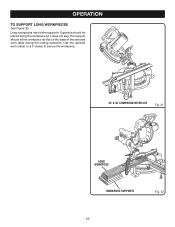
.... Supports should let the workpiece lay flat on the base of the saw and work clamp or a C-clamp to SUPPORT LONG WORKPIECES
See Figure 32. OPERATION
to secure the workpiece.
45° x 45° COMPOUND MITER CUT
Fig. 31
0
Long
0
workpiece
Workpiece supports
Fig. 32
26
English Manual - Page 27
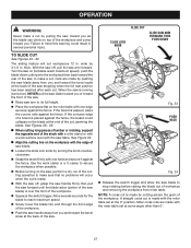
... top of the stock with a roller stand or with a work clamp or a C-clamp to make a cut. Fig. 33
PUSH BACK
Fig. 34 Release the switch trigger and allow the saw blade.
Loosen the slide lock knob by turning the knob counterclockwise.
Grasp the stock firmly with the edge of saw blade to its full...
English Manual - Page 32

... bevel lock lever to relock the bevel. To Adjust THE BEvel pivot
See Figure 40.
Also, over a period of
scrap wood.
Plug the saw into the power source and make a slight cut...Make any adjustment, make sure the tool is cutting accurately.
TO ADJUST THE LASER GUIDE
See Figure 41. Failure to heed this warning could result in the switch trigger. To adjust the laser, loosen...
English Manual - Page 33
.... Loosen the bevel lock lever by turning the knob counterclockwise. Square the blade to maintain full cutting capacities. Note: The above procedure can be necessary to loosen the indicator screws...the hex nut. Make adjustments if needed. The saw blade is factory set to provide maximum cutting capacity for
the positive stop adjustment screw), loosen the lock nut securing the ...
Repair Sheet - Page 4

...Power Cord 1 Bevel Lock Lever 1 Washer 1 Arm Support Bracket 1 Miter Handle Cap 1 Bevel Scale Label 1 Connection Shaft 1 * Screw (M6 x 20 mm Hex Soc. SLIDING MITER SAW ...98 089100113098 99 089100113099
PARTS LIST
DESCRIPTION
QTY. Hd 2 Slide Lock Knob, for Slide Bar 1 * Screw (M4 x 8 mm Pan Hd 1 Bevel Pointer 1 Sliding Bar 2 Lock Ring (65Mn 2 Roller 2 Sleeve Bearing 1 Screw (M5...
Repair Sheet - Page 5

... B Grommet 1 Spacer 1 Screw, for Bevel Lock Knob 1 Spring, for Bevel Lock Knob 1 Bevel Lock Bolt (M10 1 Data Label 1 * Screw (M4 x 25 mm Pan Hd 1 Spring Washer (M8 4 * Hex Key (5 mm 1 * Hex Key (6 mm 1 Wrench 1 Adjustment Washer 1 No Hands Label 2 Operation Label 2 Miter Lock Label 1 Laser Warning Label 1 Sliding Fence Instruction Label 1 Loosen Bolt Indicator Label 1 Exactline...
Repair Sheet - Page 6

...129-136 1
KEY
PART
NO. Key Nos. 2, 4-8, 10-12, 58-59, 68, 99, 127 and 185 1
Operator's Manual
* Standard Hardware Item - MODEL NUMBER TSS100L
The model number will be found on a plate attached to the motor ...64-65, 67-68, 70, 83, 95, 99, 119, 155 166-169, 173 and 190-194 1
Slide Bar Guard Support Bracket Assembly (Inc. May Be Purchased Locally Key Nos. 26-30, 68, 106-107, 180 and ...
Similar Questions

Is There A Replacement For Ryobi Tss101l D Handle & Switch?
Part #s for above: 089100121610 089100121112 Have apparently discontinued. Does anyone have a fix?
Part #s for above: 089100121610 089100121112 Have apparently discontinued. Does anyone have a fix?
(Posted by Math72285 3 years ago)

How To Replace The Bevel Lock Washer On A Ryobi Rts30
(Posted by mike1QWJani 10 years ago)

Ryobi Tss101l Laser Not Working?
I have a brand new Ryobi TSS101L and I see no evidence of a laser working. I looked through the manu...
I have a brand new Ryobi TSS101L and I see no evidence of a laser working. I looked through the manu...
(Posted by linexyc 11 years ago)

Ryobi Tss101l Won't Start.
My 10" mitre saw is getting electricity to the switch and when I pull the trigger the current return...
My 10" mitre saw is getting electricity to the switch and when I pull the trigger the current return...
(Posted by dtwood1 11 years ago)

Charger Has Green Light But Will Not Operate Any Of My Tools
riboyi lithium 18v P103 battery has a green light from charger but will not run andy of my tools
riboyi lithium 18v P103 battery has a green light from charger but will not run andy of my tools
(Posted by jmschaefer 12 years ago)