Garmin GMI 10 Digital Marine Instrument Display Support Question
Garmin GMI 10 Digital Marine Instrument Display Support Question
Find answers below for this question about Garmin GMI 10 Digital Marine Instrument Display.Need a Garmin GMI 10 Digital Marine Instrument Display manual? We have 5 online manuals for this item!
Question posted by Savithri on August 9th, 2012
7 Power / Data Pin Details
Pl provide 7 power / data p[in details to interface GMI 10 with GPS 78Sc
Current Answers
Related Garmin GMI 10 Digital Marine Instrument Display Manual Pages
Important Safety and Product Information - Page 2
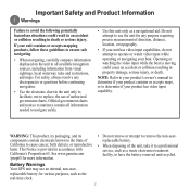
... battery removed and recycled. Battery Warnings Your GPS unit may use an internal, non-userreplaceable...watching the video input while the boat is provided in the unit only to facilitate, not ... Official government charts and notices to mariners contain all available navigation sources, including...• When navigating, carefully compare information displayed on the unit to all information needed ...
Installation Instructions, S/N 19Wxxxxxx - Page 1
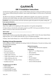
...GMI 10. GMI 10 Installation Instructions
To obtain the best possible performance, install your GMI 10 Marine Instrument according to power. 4.
Connect the GMI 10 to www.garmin.com/support/. WARNING: See the Important Safety and Product Information guide in .
(90mm)
hole
saw,
• Power/data...) 800-1020; B
Printed in the space provided below.
January, 2008
190-00892-02 Rev.
Installation Instructions, S/N 19Wxxxxxx - Page 2
...
the
mounting
surface
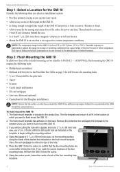
along the inside of the cables for power and data. Step 2: Flush Mounting the GMI 10
In addition to four of the included mounting screws (number 8 ANSI (4.2 × 1.4 DIN7981)), flush mounting the GMI 10
requires the following when you select an installation location:
• Provides optimal viewing as indicated on the
template to begin...
Installation Instructions, S/N 19Wxxxxxx - Page 3
... 28 1/8 27
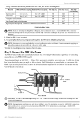
Pilot Hole Size Table
Note: If you are used for NMEA 0183 connections, and do not have to power and provides interface capabilities for normal operation of the GMI 10.
You can damage the GMI 10 and void the warranty. The other wires are mounting the chartplotter in -line fuse holder supplied with a cable assembly...
Installation Instructions, S/N 19Wxxxxxx - Page 4
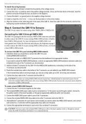
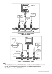
... the NMEA 2000 network, and connect each end of the boat if possible, or through NMEA 2000 The GMI 10 is not long enough, you have an existing NMEA 2000 network on the diagram.) 3. Power/data
NMEA 2000
2. Connect the red (+ or positive) wire to the positive voltage terminal. (If you just added to...
Installation Instructions, S/N 19Wxxxxxx - Page 5
... included)
T-connector (included)
NMEA 2000 device
(not included)
Drop cable (included)
Existing NMEA 2000 network
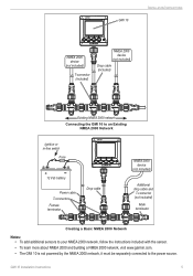
Connecting the GMI 10 to an Existing NMEA 2000 Network
Ignition or in-line switch
Fuse
+
-
12 Vdc battery
Power cable
T-connectors
Female terminator
Drop cable
NMEA 2000 device
(not included)
Additional drop cable and
T-connector (not included...
Installation Instructions, S/N 19Wxxxxxx - Page 6
...>
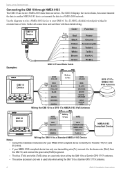
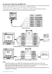
Wiring the GMI 10 to a GPS 17x NMEA 0183 HVS Antenna
GPS 17/17x NMEA 0183 HVS Antenna
GMI 10 Device
>
WIRE COLOR
Fuse RED 1 A BLACK
BROWN GREEN
- + Battery
12 Vdc
WIRE
RED POWER GND NMEA GND
...>
Examples:
GMI 10 Device
GMI 10 Power/Data Cable
WIRE COLOR
+
- The GMI 10 displays the received data, but cannot transmit the data to another NMEA 0183 device or transmit the data to your ...
Installation Instructions, S/N 19Wxxxxxx - Page 7
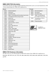
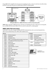
... Transmit/Receive PGN List Group Function Product Information
The GMI 10 is NMEA 2000 certified
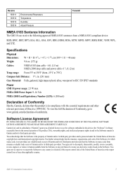
NMEA 0183 Sentence Information
The GMI 10 can be received and transmitted by a GMI
10 when communicating with a NMEA 2000-compliant device. Route/WP information GNSS DOPs GNSS Sats in View Wind Data Environmental Parameters Environmental Parameters Temperature Humidity Actual Pressure
Transmit...
Installation Instructions, S/N 19Wxxxxxx - Page 8
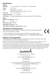
...Power/data cable - 6 ft (1.8 m) NMEA 2000 drop cable and power cable- 6 1/2 ft (2 m)
Temp range: 5°F (-15°C) to 158°F (70°C)
Compass Safe Distance: 9 1/2 in. (241 mm)
Case Material: Fully gasketed, high-impact plastic alloy, waterproof to IEC 529 IPX7 standards
Power GMI 10 power input source: 8-32 Vdc
Fuse:
AGC/3AG - 1 A
GMI 10 power usage: 2.5 W max
NMEA 2000 Power...
Installation Instructions, S/N 1Y3xxxxxx - Page 1
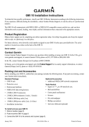
... USA, go to www.garmin.com/support and click Contact Support for in the space provided below. For future reference, write down the serial number assigned to your GMI 10 1.
GMI 10 Installation Instructions
To obtain the best possible performance, install your GMI 10 Marine Instrument according to the following items. If any questions while installing or using your...
Installation Instructions, S/N 1Y3xxxxxx - Page 3
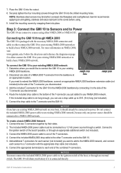
... the necessary NMEA 2000 connectors and cable to either connect the GMI 10 to sensors using . 9. NMEA 0183 Data
NMEA 2000
If you need to extend the NMEA 2000 backbone, connect an appropriate NMEA 2000 backbone extension cable (not included) to a 12 Vdc power source through an external switch.
Notice You must be connected...
Installation Instructions, S/N 1Y3xxxxxx - Page 4
... included)
T-connector (included)
NMEA 2000 device
(not included)
Drop cable (included)
Existing NMEA 2000 network
Connecting the GMI 10 to an Existing NMEA 2000 Network
Ignition or in-line switch
Fuse
+
-
12 Vdc battery
Power cable
T-connectors
Female terminator
Drop cable
NMEA 2000 device
(not included)
Additional drop cable and
T-connector (not included...
Installation Instructions, S/N 1Y3xxxxxx - Page 5
... 10 can receive NMEA 0183 data from one device.
GMI 10 Device
Color
Function
Black
Yellow
>
Blue
>
White
Brown
Green
> >
GMI 10 Data Cable
Accessory Off(-) Accessory On(+)
Tx/A(+) Tx/B(-) Rx/A(+) Rx/B(-)
GMI 10 Device
WIRE COLOR
+
-
The GMI 10 displays the received data, but cannot transmit the data to another NMEA 0183 device or transmit the data to a Garmin GPS...
Installation Instructions, S/N 1Y3xxxxxx - Page 6
... Battery 12 Vdc
WIRE FUNCTION
POWER
GREEN
NMEA GND
BLACK
POWER GND
BROWN
Tx
NMEA 0183Compatible
Device
>
>
Wiring the GMI 10 to a NMEA 0183 Device ...Data Datum Cross Track Error Navigation Data Navigation -
Rapid Update COG & SOG - Command/Request/ Acknowledge Group Function Transmit/Receive PGN List Group Function Product Information
The GMI 10 is NMEA 2000 certified
GMI 10...
Installation Instructions, S/N 1Y3xxxxxx - Page 7
...;
111
×
48
mm)
Weight:
9.6 oz. (272 g)
Cables:
NMEA 0183 data cable - 6 ft. (1.8 m) NMEA 2000 drop cable and power cable- 6 1/2 ft. (2 m)
Temp range: From 5°F to the Software remain in Garmin and/or its third-party providers.
Software License Agreement
BY USING THE GMI 10, YOU AGREE TO BE BOUND BY THE TERMS AND CONDITIONS...
Quick Start Manual - Page 2
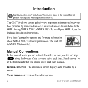
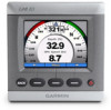
... and Product Information guide in the product box for more information about your GMI 10, use the soft keys ( ) along the bottom of compatible sensors and for product warnings and other important information. Instrument Screen-the instrument screen displays data provided by connected sensors.
Menu Screens-screens used to the GMI 10 using NMEA 2000® or NMEA 0183.
Quick Start Manual - Page 3
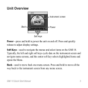
Typically, the left and right soft keys cycle data on the GMI 10. Unit Overview
Instrument screen
Back
Power
Soft keys
Power-press and hold to move back one menu screen. Back-used to power the unit on and off. Press and quickly release to the instrument screen from any menu screen.
Press and hold to navigate the menus...
Quick Start Manual - Page 4
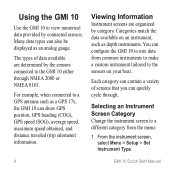
... are determined by connected sensors. For example, when connected to view numerical data provided by the sensors connected to the sensors on an instrument, such as depth instruments.
Using the GMI 10
Use the GMI 10 to a GPS antenna such as a GPS 17x, the GMI 10 can show GPS position, GPS heading (COG), GPS speed (SOG), average speed, maximum speed obtained, and distance traveled (trip...
Quick Start Manual - Page 5

Cycling Through Instrument Screens in that category. Choose from the categories listed below.
• Surface-GPS or water speed, GPS heading or magnetic sensor heading, and odometer.
• Water-depth and water temperature.
•... use the soft keys under the left and right arrows to cycle through instrument screens
2. GMI 10 Quick Start Manual
• Custom-arrange a custom set of...
Quick Start Manual - Page 6
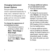
..., adding Trip Speed Graphics to a speed gauge, viewing a watertemperature graph, or adding fuel, select the option you want to show either GPS Heading (COG) or Heading from the heading sensor.
3. Changing Instrument Screen Options Data provided on an instrument screen is showing a gauge or a graph, select Menu > Show Number. To change the appearance of an...
Similar Questions


Can The Gmi 10 Be Set At Home Before Going On The Water ?thx Jon
(Posted by Anonymous-58453 11 years ago)
Can The Gmi 10 Be Set On Ground
(Posted by Anonymous-58453 11 years ago)

Gmi 10 Switches Off After Few Hours
Hello, my new GMI 10 installed in my new sailing yacht initially works well, but switches off with b...
Hello, my new GMI 10 installed in my new sailing yacht initially works well, but switches off with b...
(Posted by hannojelden 12 years ago)