Canon PC950 Support Question
Canon PC950 Support Question
Find answers below for this question about Canon PC950 - PC 950 B/W Laser.Need a Canon PC950 manual? We have 1 online manual for this item!
Question posted by robynbrownlee on August 26th, 2012
Canon Pc 950 Where Can I Buy A Replacement Scanning Tube/lamp?
lamp insufficient intensity to produce a clear copy
Current Answers
Related Canon PC950 Manual Pages
Service Manual - Page 7
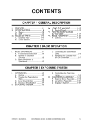
... Circuitry 2-2 C. Scanner Drive System ..........3-4
II. Scanner Drive Assembly .... 3-13 B. CANON PC800s/900s REV.0 AUG. 1999 PRINTED IN JAPAN (IMPRIME AU JAPON)
v Cross Section...13
IV. BASIC OPERATIONS 2-1 A. Outline 3-1 B. Exposure System 3-37
COPYRIGHT © 1999 CANON INC. SPECIFICATIONS 1-2
A. IMAGE FORMATION 1-20 A.
USING THE MACHINE 1-15 A. Controlling the...
Service Manual - Page 14
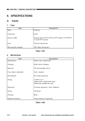
... Charging Exposure Copy density adjustment Development Pickup
Separation Fixing Cleaning Original orientation
Desk top
Descriptions
Fixed
Halogen lamp (80 V/...pc.) Single-feeder (single-feeder type) Multifeeder (multifeeder type) Curvature separation + static eliminator Flat heater Blade Center reference (copyboard)
Table 1-202
1-2
COPYRIGHT © 1999 CANON INC. Copier
1.
CANON...
Service Manual - Page 32
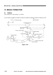
... construction of the machine is as follows:
Scanning lamp
Copyboard glass Fixed focal point lens
Side blanking lamp (front, rear)
Primary charging roller
Developing blade
Fixing assembly
Cleaning blade
Developing cylinder
Photosensitive drum
Figure 1-601
Transfer charging roller Static eliminator
1-20
COPYRIGHT © 1999 CANON INC. IMAGE FORMATION
A. CHAPTER 1 GENERAL DESCRIPTION...
Service Manual - Page 38
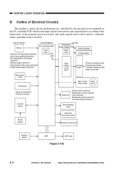
...path roller paper detection
• Single-feeder paper detection
Composite
power supply PCB
Scanning lamp
Q900
CPU
Fixing heater
Highvoltage circuit
block
Contact PCB
• Primary charging roller... solenoid
Side blanking lamp
Power switch
Scanner/ lens drive motor
Scanner cooling fan
Sensor/ switch
ADF
ADF load
Figure 2-102
2-2
COPYRIGHT © 1999 CANON INC. Outline of...
Service Manual - Page 39
CANON PC800s/900s REV.0 AUG. 1999 PRINTED IN JAPAN (IMPRIME AU JAPON)
2-3 CHAPTER 2 BASIC OPERATION
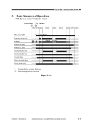
C.
Basic Sequence of Operations
• A4R, Direct, 2 Copies, Continuous, Cassette
Power switch Copy Start key ON ON
STBY INTR AER SCFW
SCRV
SCFW
SCRV LSTR STBY
Main motor (M1) Scanning lamp (LA1) Scanner Primary AC bias Primary DC bias Developing AC...
Service Manual - Page 40
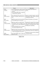
... in Direct.
Neutralizes the drum surface potential as the forward speed used in preparation for -
Table 2-101
2-4
COPYRIGHT © 1999 CANON INC.
Illuminates the original by the scanning lamp, and the reflected optical image is pressed.
Description Waits until the Copy Start key is moving forward. • The distance varies according to the
selected...
Service Manual - Page 59
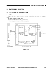
CHAPTER 3 EXPOSURE SYSTEM
II. tions: • Turning on/off the scanning lamp. • Controlling the intensity of the scanning lamp. • Monitoring the state (on/off) of the scanning lamp.
(Q101)
Intensity adjustment (Q900) signal
Serial communication
PWM_1KHz
Lamp activation signal
LAMP_ON
9
+
4-
CANON PC800s/900s REV.0 AUG. 1999 PRINTED IN JAPAN (IMPRIME AU JAPON)
3-9
Outline ...
Service Manual - Page 61
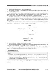
...) on the
composite power supply PCB as long as the scanning lamp remains on.
CANON PC800s/900s REV.0 AUG. 1999 PRINTED IN JAPAN (IMPRIME AU JAPON)
3-11 Controlling the Intensity of the Scanning Lamp The intensity of the lamp is not detected for 1 sec or more although the
scanning lamp activation signal is 56 V for the 120 V model (108.5 V for...
Service Manual - Page 89
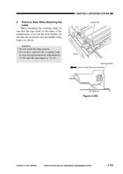
... you have replaced the scanning lamp,
be sure that the logo mark (or the name of the lamp is toward the front. Points to perform intensity adjustment (p. 11-42) and AE adjustment (p. 11-43). CHAPTER 3 EXPOSURE SYSTEM
Logo mark
(front) Scanning lamp
(mirror mount moving in reverse)
45 (approx.)
Figure 3-350
COPYRIGHT © 1999 CANON INC.
CANON PC800s/900s...
Service Manual - Page 112
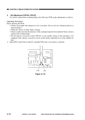
... many photos or large headings.)
• Obtain five sheets of white sheets of paper. • Check to make sure that the intensity of the scanning lamp has been adjusted when you have replaced the scanning lamp or the AE sensor PCB, make adjustments as follows:
Operating Procedure Before Starting the Work
• Obtain a newspaper showing more...
Service Manual - Page 293
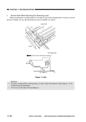
... reverse)
45˚ (approx.)
Figure 11-242 Caution: • If you have replaced the scanning lamp, you must adjust the intensity of the lamp (p. 11-42) and perform AE adjustment. • Do not touch the lamp when handling it.
11-28
COPYRIGHT © 1999 CANON INC. CHAPTER 11 TROUBLESHOOTING
f. Further, be sure that the protrusion near its...
Service Manual - Page 306
.... CHAPTER 11 TROUBLESHOOTING
C. AE mechanism)
1. Leading edge non-image width 4. CANON PC800s/900s REV.0 AUG. 1999 PRINTED IN JAPAN (IMPRIME AU JAPON)
11-41 Electrical
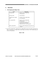
1. Intensity of the scanning lamp 2. AE mechanism 3. After Replacing the Major Parts
Parts Scanning lamp
AE sensor PCB Composite power supply PCB*1 DC controller PCB
ADF controller PCB
Adjustment 1. Excute original...
Service Manual - Page 307
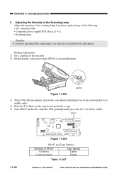
Adjusting the Intensity of the Scanning Lamp Adjust the intensity of the scanning lamp if you have replaced any of VR107 Clockwise
Counterclockwise
Copy density Lighter Darker
Table 11-207
11-42
COPYRIGHT © 1999 CANON INC. SW101
Figure 11-263
3) Turn off the AE mechanism, and set the copy density adjusting lever on the control panel to its middle index...
Service Manual - Page 308
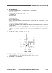
... COPYRIGHT © 1999 CANON INC. SERVICE
JP104
JP103
Figure 11-265
2) While keeping the condition in step 1), turn on the power. • The scanning lamp will turn on the DC controller PCB. AE Adjustment Perform this adjustment if you have replaced any of the scanning lamp has been adjusted when you have replaced the
scanning lamp. • Set the...
Service Manual - Page 319
Replace the cartridge.
2. Mount the transfer charging roller correctly.
2. Clean the scanning lamp, reflecting plate, lens, and mirror.
CANON PC800s/900s REV.0 AUG. 1999 PRINTED IN JAPAN (IMPRIME AU JAPON)
End.
Is the problem corrected? CHAPTER 11 TROUBLESHOOTING
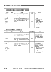
4 The copy has uneven density. (darker at front) 5 The copy has uneven density. (lighter at front)
Cause...
Service Manual - Page 320
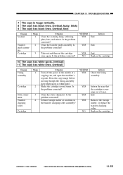
...Check the fixing
assembly.
Does the copy image before moving through the fixing assembly have white spots or white lines?
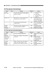
CANON PC800s/900s REV.0 AUG. 1999 ...copy has black lines. (vertical, fuzzy, thick) 9 The copy has black lines. (vertical, fine)
Cause Scanner
Transfer guide assembly Cartridge
Step 1
2
Checks Clean the scanning lamp, reflecting plate, lens, and mirror. NO Replace...
Service Manual - Page 323
... power supply PCB). Check the feeding system.
11-58
COPYRIGHT © 1999 CANON INC. Is abnormal noise heard from the scanner motor?
Scanning system Feeding system
3 Make a reduced copy, and compare it . YES/NO YES YES NO
YES NO
Action Replace the scanning lamp. End. Cause Scanner drive cable
Scanner rail
Feeding system Cartridge
Step 1
2
3 4
Checks...
Service Manual - Page 324
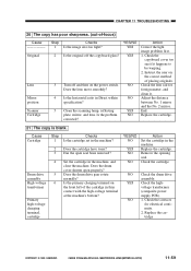
...'s bottom? Clean the scanning lamp, reflecting plate, mirror, and lens. Is the problem corrected? Check the lens rail for electrical continuity.
2.
Replace the cartridge. CANON PC800s/900s REV.0 AUG.... 1999 PRINTED IN JAPAN (IMPRIME AU JAPON)
11-59 CHAPTER 11 TROUBLESHOOTING
20 The copy has poor sharpness. (out...
Service Manual - Page 330
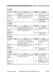
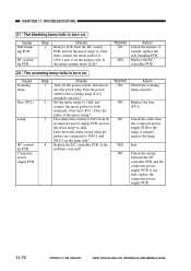
... user to turn on when the Copy Start key is turned on ." YES/NO NO
YES
Action See "The scanning lamp fails to use a frequency stabilizer. NO Replace the DC controller PCB.
11 E261... scanning lamp turn on ? End.
if normal, replace PS2.
End. Check the wiring from J203 and J204 on the composite power supply PCB and J103 and J104, respectively, on the power switch.
CANON PC800s...
Service Manual - Page 337
... DC controller PCB. Is the problem corrected? if normal, replace the lamp. if normal, replace the composite power supply PCB.
11-72
11-72
COPYRIGHT © 1999 CANON INC. Is the meter reading about 20 Ω?
YES/NO
Action
NO Mount the scanning
lamp correctly.
Cause Scanning lamp
Fuse (FU1)
Lamp
DC controller PCB Composite power supply PCB
Step...
Similar Questions

How To Scan Using Mac In Canon Mf 6590
(Posted by shjvs1 9 years ago)

Pc 940 Copier Makes Grinding Noise. What Is The Cause?
(Posted by Anonymous-143110 9 years ago)

Canon Mf6540 How To Network Scanning
(Posted by curtflas 9 years ago)

Does My Canon Pc950 Have A Hard Drive
(Posted by mdawahojnoski 11 years ago)

Mx7600 Cleaning Sheets
Where can I buy replacement cleaning sheets for the Canon MX7600?
Where can I buy replacement cleaning sheets for the Canon MX7600?
(Posted by Anonymous-20221 13 years ago)