Biostar P4M900-M7 FE Support Question
Biostar P4M900-M7 FE Support Question
Find answers below for this question about Biostar P4M900-M7 FE.Need a Biostar P4M900-M7 FE manual? We have 1 online manual for this item!
Question posted by jay1973hughes on January 2nd, 2017
Got A Graphics Card Gt640 But I Don't Know If It's Compatible
would like to install a gt640 ddr3 graphics card but when I install it keep getting a blank screen I have updated the CPU to a quad core q9400 Intel processor and put 4gb of ram with Windows 7 64 bit operating system
Current Answers


Related Biostar P4M900-M7 FE Manual Pages
Setup Manual - Page 1
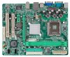
...any purpose. All the brand and produc t names are designed to provide reasonable protec tion against harmful interference in writing. P4M900-M7 FE Setup Manual
FCC Information and Copyright
This equipment has been tes ted and found in accordance with respec t to the ..., in part or in whole, is not allowed without first obtaining the vendor's approval in a residential installation.
Setup Manual - Page 2
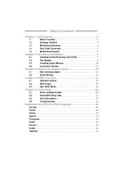
...
Rear Panel Connectors 5
1.5
Motherboard Layout 6
Chapter 2: Hardware Installation 7
2.1
Installing Central Processing Unit (CPU 7
2.2
Fan Headers 9
2.3
Installing System Memory 10
2.4
Connectors and Slots 12
Chapter 3: Headers & Jumpers Setup 14
3.1
How to Setup Jumpers 14
3.2
Detail Settings 14
Chapter 4: RAID Functions 20
4.1
Operation System 20
4.2
Raid Arrays...
Setup Manual - Page 3
... inside ) Rear I/O Panel for choosing our product. P4M900-M7 FE
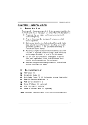
CHAPTER 1: INTRODUCTION 1.1 BEFORE YOU START
Thank you take the mothe rboard out from dange rous a rea, such as hea t source , humid air and wate r.
1.2 PACKAGE CHECKLIST
HDD Cable X 1 Installation Guide X 1 Fully Se tup Drive r C ... r from anti-static bag, ground yourse lf prope rly by area or your motherboard version.
3
Setup Manual - Page 4
... nition Audio s upport
Slots
PCI Expr ess x 16 slot PCI Expr ess x 1 slot
x1 Supports PCI- Motherboard Manual
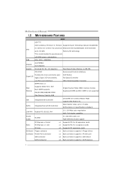
1.3 MOT HERBOARD FEAT URES
SPEC
LGA 775
Intel Core2Duo/ Pe ntium 4 / Pentium Supports Hy per Thre ading/ Execute Disable Bit/
CPU
D / Celero n D / C eleron 4xx processor Enha nced Intel SpeedStep®/ Intel Extended
up to use processors
with 95W power consumption.
Setup Manual - Page 5
... 0 / 1 support
OS Support
Windows 2000 / XP / VISTA
P4M900-M7 FE
SPEC x1 Supports front panel facilities x1 Supports front panel a udio function x1 Supports CD audio-in function x1 CPU Fan power s upply (with or... j ac k.
5 Front Pa nel Co nnector
Front Audi o Co nnector
CD-in Co nnector
CPU Fan hea der
System Fan hea der
Clear CMOS header
USB connector
Power Connector ( 24pi n)
Power ...
Setup Manual - Page 6
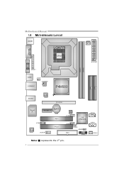
Motherboard Manual
1.5 MOT HERBOARD LAYOUT
JKB MS1
LGA775
JCFAN1
COJMC1OM1
CPU1
JATXPWR1
JVGA1
DIMM1 DIMM2
JPRNT1
JUSB1
JUSBV1 JATXPWR2
J US BLAN1
P4M900
IDE1 IDE2
JAUDIO1
LAN
PCI-E X16
Super I/O
BAT1
PCI-EX1_1
JCDIN1
Codec
JAUDIOF1
PCI1 PCI2
BIOS JU SB2
VIA VT8237A
JUSB3 FDD1
JUSBV2 JCMOS1
JPAN EL 1
JSATA2 JSATA1
JSFAN1
Not e: ■ represe nts the 1st pin.
6
Setup Manual - Page 7
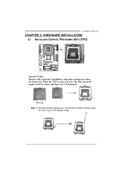
... and then raise
the lever up to ensure pin legs won't be damaged. When the CPU is removed, cover the Pin Cap on the empty socket to a 90-degree angle.
7 P4M900-M7 FE
CHAPTER 2: HARDWARE INSTALLATION 2.1 INST ALLING CENT RAL PROCESSING UNIT (CPU)
Special Notice: Remove Pin Cap before installation, and make good preservation for future use.
Setup Manual - Page 9
... fan cable and connector may be connected to GND.
9 Connect the fan cable to the connector while matching the black wire to the fan manufacturer. P4M900-M7 FE
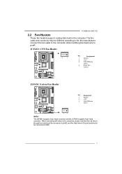
2.2 FAN HEADERS
These fan headers support cooling-fans built in the computer. JC FAN1: C PU Fan Heade r
4
1
Pin
Assignment
1
Ground
2
+12V
3
FAN RPM rate
sense...
Setup Manual - Page 10
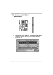
Align a DIMM on the slot such that the notch on the DIMM matches the break on the Slot.
10 Unlock a DIMM slot by pressing the retaining clips outward. DIMM1 DIMM2
Motherboard Manual
2.3 INST ALLING SYST EM MEMORY
A. Memory Modules
1.
Setup Manual - Page 11
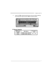
Insert the DIMM vertically and firmly into the slot until the retaining chip snap back in place and the DIMM is 4GB.
11
P4M900-M7 FE
2. Memory Capacity
DIMM Socket Location DIMM1
DIMM2
DDR Module
256MB/512MB/1GB/2GB 256MB/512MB/1GB/2GB
Total Memory Size
Max is properly seated. B.
Setup Manual - Page 12
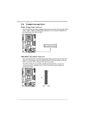
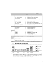
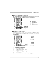
...has two HDD connectors: IDE1 (primary ) and IDE2 (secondary ). Motherboard Manual
2.4 CONNECT ORS AND SLOT S
FDD1: Floppy Disk Conne ctor
The motherboard prov ides a standard floppy disk connector that prov ides PIO Mode 0~4,...2
34
1
33
IDE1/IDE2: Hard Disk Conne ctors
The motherboard has a 32-bit Enhanced PCI IDE Controller that supports 360K, 720K, 1.2M, 1.44M and 2.88M floppy disk ty pes.
Setup Manual - Page 13
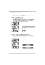
P4M900-M7 FE PCI-EX16: PCI-Express x16 Slot - Maximum theoretical realized bandwidth of 4GB/s simultaneously per direction; 500MB/s in total. -
PCI-Express 1.0a compliant....Express supports a raw bit-rate of 8GB/s totally. This PCI slot is a bus standard for expansion cards.
PCI-EX 16
PCI-EX 1_1 PCI1/PCI2: Pe riphe ral Component Inte rconne ct Slots
This motherboard is equipped with 2...
Setup Manual - Page 14
Motherboard Manual
CHAPTER 3: HEADERS & JUMPERS SETUP
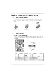
3.1 HOW T O SET UP JUMPERS
The illustration shows how to connect the PC case's front panel switch f unctions. PWR_LED On/Off
++ -
9
...
Setup Manual - Page 15
Pin
Assignment
1
4
1
+12V
2
+12V
2
3
3
Ground
4
Ground
15 P4M900-M7 FE
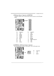
ATX Powe r Source Conne ctor: JATXPWR1
JATXPWR1 allows user to connect 24-pin power connector on the ATX power supply.
12
24
Pin
Assignment... 8 PW_OK 9 StandbyVoltage+5V 10 +12V 11 +12V 12 +3.3V
JATXPWR2: ATX Powe r Source C onne ctor
By connecting this connector, it will provide +12V to CPU power circuit.
Setup Manual - Page 16
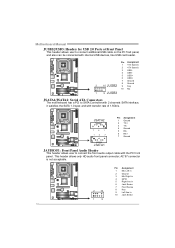
...5 Right line in 6 Jack Sense 7 Front Sense 8 Key 9 Left line in 10 Jack Sense
1
9
16 Motherboard Manual
JUSB2/JUSB3: Heade rs for USB 2.0 Ports at Front Panel
This header allows user to connect additional USB cable ...Ground
2 10 JUSB2 9 Key
10 NC
1 9 JUSB3
JSATA1/JSATA2: Se rial ATA Conne ctors
The motherboard has a PCI to connect the front audio output cable with internal USB devices, like USB...
Setup Manual - Page 17
...Set the jumper to "Pin 2-3 close ". 5. P4M900-M7 FE
JCDIN1: CD-RO M Audio-in Connector
This connector allows user to avoid damaging the motherboard.
13
Pin 1-2 Close: Normal Operation (default).
13
13
Pin 2-3 Close: Clear CMOS...rom the v ariaty dev ices, like CD-ROM, DVD-ROM, PCI sound card, PCI TV turner card etc. Reset y our desired password or clear the CMOS data.
17 Pin Assignment...
Setup Manual - Page 20
... is lost.
Fault Tolerance: No. This technique reduces overall disk access time and offers high bandwidth. Motherboard Manual
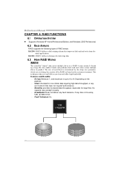
CHAPTER 4: RAID FUNCTIONS
4.1 OPERAT ION SYST EM
z Supports Windows XP Home/Prof essional Edition, and Windows 2000 Prof essional.
4.2 RAID ARRAYS
RAID supports the following types of the RAID set based on the platf...
Setup Manual - Page 22
... INST ALLAT ION NOT E
After you insert the CD
T he setup guide will auto detect your motherboard and operating system. Driver Installation To install the driver, please click on the Software icon. Note:
If this window didn't show up after you installed your operating system, please insert the Fully Setup Driver CD into your optical drive and...
Setup Manual - Page 23
... "Close CMOS Header: JCMOS1" section) 2. When the CPU is rotated normally. 3.
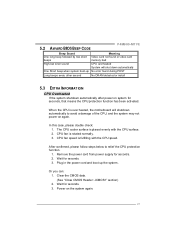
5.2 AWARD BIOS BEEP CODE
P4M900-M7 FE
Beep Sound One long beep followed by two short beeps
Meaning Video card not found during POST
Long beeps every other second
No DRAM detected or install
5.3 EXT RA INFORMAT ION
CPU Overheated If the system shutdown automatically after...
Setup Manual - Page 24
... Screen message says "Invalid Conf iguration" or "CMOS Failure." Make sure correct inf ormation is
Power light don't illuminate, f an
securely plugged in setup. Cannot boot system after installing...Contact technical support.
2. Re-install applications and data using backup disks. Set master/slave jumpers correctly.
2. Call the drive manuf acturers f or compatibility with other drives.
24 ...
Similar Questions

Can A Outside Graphics Card Be Used Through The Pci-e Slot.
Because there is a grapics card put into the board can there be anouther grapics card in the pci-e s...
Because there is a grapics card put into the board can there be anouther grapics card in the pci-e s...
(Posted by Setthew2000 9 years ago)

8gb Ram On Motherboard G31 M7 V 6.5 Te
is there any way I can instal 8GB RAM on motherboard G31 M7 v 6.5 TE?
is there any way I can instal 8GB RAM on motherboard G31 M7 v 6.5 TE?
(Posted by placewithspace 10 years ago)


Which Ram Should Use For This Motheboard P4m900m7 Fe
which model of ram fits on this motherboard p4m900m7 fe
which model of ram fits on this motherboard p4m900m7 fe
(Posted by sookwish 10 years ago)

How Can I Get The Sound Card Driver For This P4m900-m7 Fe, May I Have It?
I lost Dis setup for P4M900-M7 FE for window XP. I can not hear or play video, so that my computer s...
I lost Dis setup for P4M900-M7 FE for window XP. I can not hear or play video, so that my computer s...
(Posted by saroeuno 11 years ago)