Setup Manual
Page 1
... to notify any purpose. The content of this user's manual is subject to be res ponsible for any party beforehand. P4M900-M7 FE Setup Manual FCC Information and Copyright This equipment has been tes ted and found in this user's manual. There is not allowed without first obtaining the vendor...generates , uses , and c an radiate radio frequency energy and, if not ins talled and used in writing. Further the vendor reserves the right to revise this publication, in part or in whole, is no representations or warranties with the instructions , may cause harmful interference to Part 15 of ...
... to notify any purpose. The content of this user's manual is subject to be res ponsible for any party beforehand. P4M900-M7 FE Setup Manual FCC Information and Copyright This equipment has been tes ted and found in this user's manual. There is not allowed without first obtaining the vendor...generates , uses , and c an radiate radio frequency energy and, if not ins talled and used in writing. Further the vendor reserves the right to revise this publication, in part or in whole, is no representations or warranties with the instructions , may cause harmful interference to Part 15 of ...
Setup Manual
Page 2
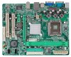
...Rear Panel Connectors 5 1.5 Motherboard Layout 6 Chapter 2: Hardware Installation 7 2.1 Installing Central Processing Unit (CPU 7 2.2 Fan Headers 9 2.3 Installing System Memory 10 2.4 Connectors and Slots 12 Chapter 3: Headers & Jumpers Setup 14 3.1 How to Setup Jumpers 14 3.2 Detail Settings 14 Chapter 4: RAID Functions 20 4.1 Operation System 20 4.2 Raid Arrays 20 4.3 How RAID Works 20 Chapter 5: Useful Help 22 5.1 Driver Installation Note 22 5.2 Award BIOS Bee p Code 23 5.3 Extra Information 23 5.4 Tro ubles ho oting 24 A ppendencies: SPEC...
...Rear Panel Connectors 5 1.5 Motherboard Layout 6 Chapter 2: Hardware Installation 7 2.1 Installing Central Processing Unit (CPU 7 2.2 Fan Headers 9 2.3 Installing System Memory 10 2.4 Connectors and Slots 12 Chapter 3: Headers & Jumpers Setup 14 3.1 How to Setup Jumpers 14 3.2 Detail Settings 14 Chapter 4: RAID Functions 20 4.1 Operation System 20 4.2 Raid Arrays 20 4.3 How RAID Works 20 Chapter 5: Useful Help 22 5.1 Driver Installation Note 22 5.2 Award BIOS Bee p Code 23 5.3 Extra Information 23 5.4 Tro ubles ho oting 24 A ppendencies: SPEC...
Setup Manual
Page 3
... cause short circuits which may differ by touching any unfastene d small parts inside ) Rear I/O Panel for choosing our product. P4M900-M7 FE CHAPTER 1: INTRODUCTION 1.1 BEFORE YOU START Thank you take the mothe rboard out from dange rous a rea, such as hea t source , humid air and wate r. 1.2 PACKAGE CHECKLIST HDD Cable X 1 Installation Guide X 1 Fully Se tup Drive r C D X 1 (full ve rsion manual files inside the case afte r installation.
... cause short circuits which may differ by touching any unfastene d small parts inside ) Rear I/O Panel for choosing our product. P4M900-M7 FE CHAPTER 1: INTRODUCTION 1.1 BEFORE YOU START Thank you take the mothe rboard out from dange rous a rea, such as hea t source , humid air and wate r. 1.2 PACKAGE CHECKLIST HDD Cable X 1 Installation Guide X 1 Fully Se tup Drive r C D X 1 (full ve rsion manual files inside the case afte r installation.
Setup Manual
Page 4
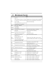
... Seri al ATA Controller Data transfer rates up to 3.8 GHz Memory 64 technology *It is 256 MB ITE 8712F Provides the most commonly used Super I/O legacy Super I/O functionality. FSB 533 / 800 / 1066 MHz Chipset Graphic VIA P4M900 VIA VT8237A Chrome9 HC 3D / 2D Graphics Max Share d Vide o Memory is recommende d to 1.5 Gb/s. SATA Version 1.0 specification complia nt. E x 1 ex pansio n cards PCI slot x2 Supports PCI expa nsion cards On Board Floppy connector x1 Each connector supports...
... Seri al ATA Controller Data transfer rates up to 3.8 GHz Memory 64 technology *It is 256 MB ITE 8712F Provides the most commonly used Super I/O legacy Super I/O functionality. FSB 533 / 800 / 1066 MHz Chipset Graphic VIA P4M900 VIA VT8237A Chrome9 HC 3D / 2D Graphics Max Share d Vide o Memory is recommende d to 1.5 Gb/s. SATA Version 1.0 specification complia nt. E x 1 ex pansio n cards PCI slot x2 Supports PCI expa nsion cards On Board Floppy connector x1 Each connector supports...
Setup Manual
Page 5
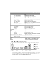
... Smart Fa n function) x1 System Fan Power supply x1 Restore CMOS data to factory defa ult x2 Each connector supports 2 fr ont panel USB ports x1 Connects to Power supply x1 Connects to Power supply x1 Connects to PS/ 2 Key board x1 Connects to PS/ 2 Mo use Serial Port Back Panel VGA Port I/O LAN port USB Port Audio J ack Board Size 190 mm (W) x 244 mm (L) Special Feature RAID 0 / 1 support OS Support Windows 2000 / XP / VISTA P4M900-M7 FE SPEC x1 Supports front panel facilities x1 Supports front panel a udio function x1 Supports CD audio-in function x1 CPU Fan power...
... Smart Fa n function) x1 System Fan Power supply x1 Restore CMOS data to factory defa ult x2 Each connector supports 2 fr ont panel USB ports x1 Connects to Power supply x1 Connects to Power supply x1 Connects to PS/ 2 Key board x1 Connects to PS/ 2 Mo use Serial Port Back Panel VGA Port I/O LAN port USB Port Audio J ack Board Size 190 mm (W) x 244 mm (L) Special Feature RAID 0 / 1 support OS Support Windows 2000 / XP / VISTA P4M900-M7 FE SPEC x1 Supports front panel facilities x1 Supports front panel a udio function x1 Supports CD audio-in function x1 CPU Fan power...
Setup Manual
Page 7
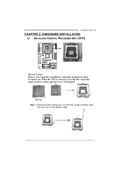
Pin Cap Step 1: Pull the socket locking lever out from the socket and then raise the lever up to ensure pin legs won't be damaged. P4M900-M7 FE CHAPTER 2: HARDWARE INSTALLATION 2.1 INST ALLING CENT RAL PROCESSING UNIT (CPU) Special Notice: Remove Pin Cap before installation, and make good preservation for future use. When the CPU is removed, cover the Pin Cap on the empty socket to a 90-degree angle. 7
Pin Cap Step 1: Pull the socket locking lever out from the socket and then raise the lever up to ensure pin legs won't be damaged. P4M900-M7 FE CHAPTER 2: HARDWARE INSTALLATION 2.1 INST ALLING CENT RAL PROCESSING UNIT (CPU) Special Notice: Remove Pin Cap before installation, and make good preservation for future use. When the CPU is removed, cover the Pin Cap on the empty socket to a 90-degree angle. 7
Setup Manual
Page 9
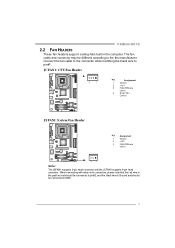
... the fan manufacturer. P4M900-M7 FE 2.2 FAN HEADERS These fan headers support cooling-fans built in the computer. The fan cable and connector may be connected to pin#1. Connect the fan cable to the connector while matching the black wire to GND. 9 JC FAN1: C PU Fan Heade r 4 1 Pin Assignment 1 Ground 2 +12V 3 FAN RPM rate sense 4 Smart Fan Control JSFAN1: System Fan He ader Pin Assignment 1 Ground 2 +12V 3 FAN RPM rate sense 3 1 Note: The JSFAN1 supports 3-pin head connector and the JCFAN1 supports 4-pin head connector.
... the fan manufacturer. P4M900-M7 FE 2.2 FAN HEADERS These fan headers support cooling-fans built in the computer. The fan cable and connector may be connected to pin#1. Connect the fan cable to the connector while matching the black wire to GND. 9 JC FAN1: C PU Fan Heade r 4 1 Pin Assignment 1 Ground 2 +12V 3 FAN RPM rate sense 4 Smart Fan Control JSFAN1: System Fan He ader Pin Assignment 1 Ground 2 +12V 3 FAN RPM rate sense 3 1 Note: The JSFAN1 supports 3-pin head connector and the JCFAN1 supports 4-pin head connector.
Setup Manual
Page 11
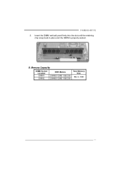
Insert the DIMM vertically and firmly into the slot until the retaining chip snap back in place and the DIMM is 4GB. 11 B. P4M900-M7 FE 2. Memory Capacity DIMM Socket Location DIMM1 DIMM2 DDR Module 256MB/512MB/1GB/2GB 256MB/512MB/1GB/2GB Total Memory Size Max is properly seated.
Insert the DIMM vertically and firmly into the slot until the retaining chip snap back in place and the DIMM is 4GB. 11 B. P4M900-M7 FE 2. Memory Capacity DIMM Socket Location DIMM1 DIMM2 DDR Module 256MB/512MB/1GB/2GB 256MB/512MB/1GB/2GB Total Memory Size Max is properly seated.
Setup Manual
Page 12
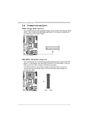
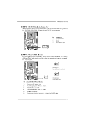
... drive ribbon cable. 2 34 1 33 IDE1/IDE2: Hard Disk Conne ctors The motherboard has a 32-bit Enhanced PCI IDE Controller that supports 360K, 720K, 1.2M, 1.44M and 2.88M floppy disk ty pes. The f irst hard drive should always be connected to four hard disk drives. Motherboard Manual 2.4 CONNECT ORS AND SLOT S FDD1: Floppy Disk Conne ctor The motherboard prov ides a standard floppy disk connector that prov ides PIO Mode 0~4, Bus Master, and Ultra DMA 33/66/100/133 f unctionality. It has two HDD connectors...
... drive ribbon cable. 2 34 1 33 IDE1/IDE2: Hard Disk Conne ctors The motherboard has a 32-bit Enhanced PCI IDE Controller that supports 360K, 720K, 1.2M, 1.44M and 2.88M floppy disk ty pes. The f irst hard drive should always be connected to four hard disk drives. Motherboard Manual 2.4 CONNECT ORS AND SLOT S FDD1: Floppy Disk Conne ctor The motherboard prov ides a standard floppy disk connector that prov ides PIO Mode 0~4, Bus Master, and Ultra DMA 33/66/100/133 f unctionality. It has two HDD connectors...
Setup Manual
Page 13
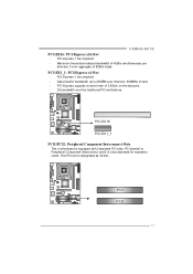
... an aggregate of 2.5Gb/s on the data pins. - 2X bandwidth ov er the traditional PCI architecture. PCI-Express 1.0a compliant. - This PCI slot is a bus standard for expansion cards. PCI stands f or Peripheral Component Interconnect, and it is designated as 32 bits. PCI-Express supports a raw bit-rate of 8GB/s totally. PCI1 PCI2 13 P4M900-M7 FE PCI-EX16: PCI-Express x16 Slot - PCI-EX1_1: PCI-Express x1 Slot - Maximum theoretical realized bandwidth of 4GB...
... an aggregate of 2.5Gb/s on the data pins. - 2X bandwidth ov er the traditional PCI architecture. PCI-Express 1.0a compliant. - This PCI slot is a bus standard for expansion cards. PCI stands f or Peripheral Component Interconnect, and it is designated as 32 bits. PCI-Express supports a raw bit-rate of 8GB/s totally. PCI1 PCI2 13 P4M900-M7 FE PCI-EX16: PCI-Express x16 Slot - PCI-EX1_1: PCI-Express x1 Slot - Maximum theoretical realized bandwidth of 4GB...
Setup Manual
Page 14
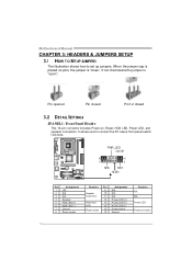
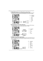
...3 N/A 4 Speaker 5 HDD LED (+) 6 HDD LED (-) 7 Ground 8 Reset control Functio n Pin 9 Speaker 10 Connec tor 11 12 Hard drive 13 LED 14 Reset button 15 16 Assignment N/A N/A N/A Power LED (+) Power LED (+) Power LED (-) Power button Ground Functio n N/A N/A Power LED Power-on pins, the jumper is "close", if not, that means the jumper is placed on button 14 It allows user to set up jumpers. Pin opened Pin closed Pin1-2 closed 3.2 DET AIL SETT INGS JPANEL1: Front Panel Heade r This 16-pin connector includes Power-on, Reset, HDD LED, Power LED, and speaker connection.
...3 N/A 4 Speaker 5 HDD LED (+) 6 HDD LED (-) 7 Ground 8 Reset control Functio n Pin 9 Speaker 10 Connec tor 11 12 Hard drive 13 LED 14 Reset button 15 16 Assignment N/A N/A N/A Power LED (+) Power LED (+) Power LED (-) Power button Ground Functio n N/A N/A Power LED Power-on pins, the jumper is "close", if not, that means the jumper is placed on button 14 It allows user to set up jumpers. Pin opened Pin closed Pin1-2 closed 3.2 DET AIL SETT INGS JPANEL1: Front Panel Heade r This 16-pin connector includes Power-on, Reset, HDD LED, Power LED, and speaker connection.
Setup Manual
Page 15
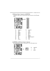
...Ground 4 Ground 15 P4M900-M7 FE ATX Powe r Source Conne ctor: JATXPWR1 JATXPWR1 allows user to connect 24-pin power connector on the ATX power supply. 12 24 Pin Assignment 13 +3.3V 14 -12V 15 Ground 16 PS_ON 17 Ground 18 Ground 19 Ground 20 NC 21 +5V 22 +5V 23 +5V 24 Ground 1 13 Pin Assignment 1 +3.3V... 2 +3.3V 3 Ground 4 +5V 5 Ground 6 +5V 7 Ground 8 PW_OK 9 StandbyVoltage+5V 10 +12V 11 +12V 12 +3.3V JATXPWR2: ATX Powe r Source C onne ctor By connecting this connector, it will provide +12V to CPU power circuit.
...Ground 4 Ground 15 P4M900-M7 FE ATX Powe r Source Conne ctor: JATXPWR1 JATXPWR1 allows user to connect 24-pin power connector on the ATX power supply. 12 24 Pin Assignment 13 +3.3V 14 -12V 15 Ground 16 PS_ON 17 Ground 18 Ground 19 Ground 20 NC 21 +5V 22 +5V 23 +5V 24 Ground 1 13 Pin Assignment 1 +3.3V... 2 +3.3V 3 Ground 4 +5V 5 Ground 6 +5V 7 Ground 8 PW_OK 9 StandbyVoltage+5V 10 +12V 11 +12V 12 +3.3V JATXPWR2: ATX Powe r Source C onne ctor By connecting this connector, it will provide +12V to CPU power circuit.
Setup Manual
Page 16
...: Se rial ATA Conne ctors The motherboard has a PCI to connect additional USB cable on the PC f ront panel, and also can be connected with internal USB devices, like USB card reader. Motherboard Manual JUSB2/JUSB3: Heade rs for USB 2.0 Ports at Front Panel This header allows user to SATA Controller with 2 channels SATA interf ace, it satisfies the SATA 1.0 spec and with transfer rate of 1.5Gb/s. JSATA2 7 41 14 7 Pin Assignment 1 Ground 2 TX+ 3 TX4 Ground...
...: Se rial ATA Conne ctors The motherboard has a PCI to connect additional USB cable on the PC f ront panel, and also can be connected with internal USB devices, like USB card reader. Motherboard Manual JUSB2/JUSB3: Heade rs for USB 2.0 Ports at Front Panel This header allows user to SATA Controller with 2 channels SATA interf ace, it satisfies the SATA 1.0 spec and with transfer rate of 1.5Gb/s. JSATA2 7 41 14 7 Pin Assignment 1 Ground 2 TX+ 3 TX4 Ground...
Setup Manual
Page 17
... the jumper on the AC. 6. Reset y our desired password or clear the CMOS data. 17 Wait f or f ive seconds. 4. Set the jumper to avoid damaging the motherboard. 13 Pin 1-2 Close: Normal Operation (default). 13 13 Pin 2-3 Close: Clear CMOS data. ※ Clear CMOS Proce dures: 1. Set the jumper to connect the audio source f rom the v ariaty dev ices, like CD-ROM, DVD-ROM, PCI sound card, PCI TV turner card etc. P4M900-M7 FE JCDIN1: CD-RO M Audio-in Connector This connector allows user to "Pin...
... the jumper on the AC. 6. Reset y our desired password or clear the CMOS data. 17 Wait f or f ive seconds. 4. Set the jumper to avoid damaging the motherboard. 13 Pin 1-2 Close: Normal Operation (default). 13 13 Pin 2-3 Close: Clear CMOS data. ※ Clear CMOS Proce dures: 1. Set the jumper to connect the audio source f rom the v ariaty dev ices, like CD-ROM, DVD-ROM, PCI sound card, PCI TV turner card etc. P4M900-M7 FE JCDIN1: CD-RO M Audio-in Connector This connector allows user to "Pin...

Setup Manual
Page 19
JUSBV1 13 13 Pin 1-2 close JU SBV 2 13 13 Pin 2-3 close Note: In order to support this function "Power-On system via USB device," "JUSBV1/ JUSBV2" jumper cap should be placed on Pin 2-3 indi viduall y. 19 JUSBV2: +5V for USB ports at f ront panel (JUSB2/JUSB3). P4M900-M7 FE JUSBV1/JUSBV2: Powe r Source Heade rs for USB Ports Pin 1-2 Close: JUSBV1: +5V for USB ports at JUSB1/JUSBLAN1. Pin 2-3 Close: JUSBV1: USB ports at front panel (JUSB2/JUSB3) are powered by +5V standby v oltage. JUSBV2: USB ports at JUSB1/JUSBLAN1 are powered by +5V standby v oltage.
JUSBV1 13 13 Pin 1-2 close JU SBV 2 13 13 Pin 2-3 close Note: In order to support this function "Power-On system via USB device," "JUSBV1/ JUSBV2" jumper cap should be placed on Pin 2-3 indi viduall y. 19 JUSBV2: +5V for USB ports at f ront panel (JUSB2/JUSB3). P4M900-M7 FE JUSBV1/JUSBV2: Powe r Source Heade rs for USB Ports Pin 1-2 Close: JUSBV1: +5V for USB ports at JUSB1/JUSBLAN1. Pin 2-3 Close: JUSBV1: USB ports at front panel (JUSB2/JUSB3) are powered by +5V standby v oltage. JUSBV2: USB ports at JUSB1/JUSBLAN1 are powered by +5V standby v oltage.
Setup Manual
Page 20
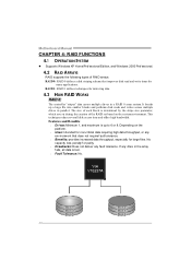
... write times for many applications. Motherboard Manual CHAPTER 4: RAID FUNCTIONS 4.1 OPERAT ION SYST EM z Supports Windows XP Home/Prof essional Edition, and Windows 2000 Prof essional. 4.2 RAID ARRAYS RAID supports the following types of RAID arrays: RAID 0: RAID 0 defines a disk striping scheme that does not require f ault tolerance. Benefits: prov ides increased data throughput, especially f or large files. If any drive in the array f ails, all...
... write times for many applications. Motherboard Manual CHAPTER 4: RAID FUNCTIONS 4.1 OPERAT ION SYST EM z Supports Windows XP Home/Prof essional Edition, and Windows 2000 Prof essional. 4.2 RAID ARRAYS RAID supports the following types of RAID arrays: RAID 0: RAID 0 defines a disk striping scheme that does not require f ault tolerance. Benefits: prov ides increased data throughput, especially f or large files. If any drive in the array f ails, all...

Setup Manual
Page 21
P4M900-M7 FE RAID 1: Every read and write is ideal f or small databases or any other application that eliminates tedious manual backups to the other drive. Drawbacks: Requires 2 driv es for the storage space of the data can be applied for high-availability solutions, or as a form of a hardware failure. Features and Benefits Drives: Minimum 2, and maximum is 2. ...
P4M900-M7 FE RAID 1: Every read and write is ideal f or small databases or any other application that eliminates tedious manual backups to the other drive. Drawbacks: Requires 2 driv es for the storage space of the data can be applied for high-availability solutions, or as a form of a hardware failure. Features and Benefits Drives: Minimum 2, and maximum is 2. ...
Setup Manual
Page 22
... setup guide will list the software available for your motherboard and operating system. Motherboard Manual CHAPTER 5: USEFUL HELP 5.1 DRIVER INST ALLAT ION NOT E After you installed your operating system, please insert the Fully Setup Driver CD into your optical drive. Click on each device driver to browse for better system performance. The setup guide will auto detect your system, click on each software title to locate and execute the file SETUP.EXE...
... setup guide will list the software available for your motherboard and operating system. Motherboard Manual CHAPTER 5: USEFUL HELP 5.1 DRIVER INST ALLAT ION NOT E After you installed your operating system, please insert the Fully Setup Driver CD into your optical drive. Click on each device driver to browse for better system performance. The setup guide will auto detect your system, click on each software title to locate and execute the file SETUP.EXE...
Setup Manual
Page 23
... for seconds. 3. When the CPU is fulfilling with the CPU surface. 2. CPU fan speed is over heated, the motherboard will shut down automatically One Short beep when system boot-up the system. In this case, please double check: 1. 5.2 AWARD BIOS BEEP CODE P4M900-M7 FE Beep Sound One long beep followed by two short beeps Meaning Video card not found during POST Long beeps every other second No DRAM detected or install 5.3 EXT RA INFORMAT ION CPU Overheated If the system...
... for seconds. 3. When the CPU is fulfilling with the CPU surface. 2. CPU fan speed is over heated, the motherboard will shut down automatically One Short beep when system boot-up the system. In this case, please double check: 1. 5.2 AWARD BIOS BEEP CODE P4M900-M7 FE Beep Sound One long beep followed by two short beeps Meaning Video card not found during POST Long beeps every other second No DRAM detected or install 5.3 EXT RA INFORMAT ION CPU Overheated If the system...
Setup Manual
Page 24
... ; inside power supply does not turn on key board does not turn 2. Keyboard lights are securely plugged in setup. Check cable running from disk to the system at any time. All hard disks are lit, and hard driv e is impossible. System only boots f rom optical driv e. 1. Re-install applications and data using backup disks. Rev iew system's equipment. Set master/slave jumpers correctly. 2. Call the drive manuf acturers f or compatibility with other drives. 24 Motherboard Manual 5.4 TROUBLESHOOT ING...
... ; inside power supply does not turn on key board does not turn 2. Keyboard lights are securely plugged in setup. Check cable running from disk to the system at any time. All hard disks are lit, and hard driv e is impossible. System only boots f rom optical driv e. 1. Re-install applications and data using backup disks. Rev iew system's equipment. Set master/slave jumpers correctly. 2. Call the drive manuf acturers f or compatibility with other drives. 24 Motherboard Manual 5.4 TROUBLESHOOT ING...


