Setup Manual
Page 3
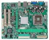
P4M900-M7 FE CHAPTER 1: INTRODUCTION 1.1 BEFORE YOU START Thank you take the mothe rboard out from dange rous a rea, such as hea t source , humid air and wate r. 1.2 PACKAGE CHECKLIST HDD Cable X 1 Installation Guide X 1 Fully Se tup Drive r C D X 1 (full ve rsion manual files inside the case afte r installation. ...the equipment. „ Keep the compute r from anti-static bag, ground yourse lf prope rly by area or your motherboard version. 3 Loose parts will cause short circuits which may differ by touching any unfastene d small parts inside ) Rear I/O Panel for choosing our ...
P4M900-M7 FE CHAPTER 1: INTRODUCTION 1.1 BEFORE YOU START Thank you take the mothe rboard out from dange rous a rea, such as hea t source , humid air and wate r. 1.2 PACKAGE CHECKLIST HDD Cable X 1 Installation Guide X 1 Fully Se tup Drive r C D X 1 (full ve rsion manual files inside the case afte r installation. ...the equipment. „ Keep the compute r from anti-static bag, ground yourse lf prope rly by area or your motherboard version. 3 Loose parts will cause short circuits which may differ by touching any unfastene d small parts inside ) Rear I/O Panel for choosing our ...
Setup Manual
Page 4
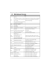
...Slots PCI Expr ess x 16 slot PCI Expr ess x 1 slot x1 Supports PCI- FSB 533 / 800 / 1066 MHz Chipset Graphic VIA P4M900 VIA VT8237A Chrome9 HC 3D / 2D Graphics Max Share d Vide o Memory is 256 MB ITE 8712F Provides the most commonly used Super I/O ... Co ntroller ITE's "Smart Guardia n" function Single Channel Mode DDR2 memory mo dule Registered DIMM and ECC DIMM is not supported IDE Integrated I /O functionality. Motherboard Manual 1.3 MOT HERBOARD FEAT URES SPEC LGA 775 Intel Core2Duo/ Pe ntium 4 / Pentium Supports Hy per Thre ading/ Execute Disable Bit/ CPU D / Celero...
...Slots PCI Expr ess x 16 slot PCI Expr ess x 1 slot x1 Supports PCI- FSB 533 / 800 / 1066 MHz Chipset Graphic VIA P4M900 VIA VT8237A Chrome9 HC 3D / 2D Graphics Max Share d Vide o Memory is 256 MB ITE 8712F Provides the most commonly used Super I/O ... Co ntroller ITE's "Smart Guardia n" function Single Channel Mode DDR2 memory mo dule Registered DIMM and ECC DIMM is not supported IDE Integrated I /O functionality. Motherboard Manual 1.3 MOT HERBOARD FEAT URES SPEC LGA 775 Intel Core2Duo/ Pe ntium 4 / Pentium Supports Hy per Thre ading/ Execute Disable Bit/ CPU D / Celero...
Setup Manual
Page 6
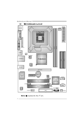
Motherboard Manual 1.5 MOT HERBOARD LAYOUT JKB MS1 LGA775 JCFAN1 COJMC1OM1 CPU1 JATXPWR1 JVGA1 DIMM1 DIMM2 JPRNT1 JUSB1 JUSBV1 JATXPWR2 J US BLAN1 P4M900 IDE1 IDE2 JAUDIO1 LAN PCI-E X16 Super I/O BAT1 PCI-EX1_1 JCDIN1 Codec JAUDIOF1 PCI1 PCI2 BIOS JU SB2 VIA VT8237A JUSB3 FDD1 JUSBV2 JCMOS1 JPAN EL 1 JSATA2 JSATA1 JSFAN1 Not e: ■ represe nts the 1st pin. 6
Motherboard Manual 1.5 MOT HERBOARD LAYOUT JKB MS1 LGA775 JCFAN1 COJMC1OM1 CPU1 JATXPWR1 JVGA1 DIMM1 DIMM2 JPRNT1 JUSB1 JUSBV1 JATXPWR2 J US BLAN1 P4M900 IDE1 IDE2 JAUDIO1 LAN PCI-E X16 Super I/O BAT1 PCI-EX1_1 JCDIN1 Codec JAUDIOF1 PCI1 PCI2 BIOS JU SB2 VIA VT8237A JUSB3 FDD1 JUSBV2 JCMOS1 JPAN EL 1 JSATA2 JSATA1 JSFAN1 Not e: ■ represe nts the 1st pin. 6
Setup Manual
Page 8
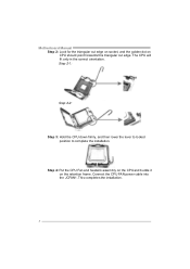
Connect the CPU FAN power cable into the JCFAN1. Step 2-1: Step 2-2: Step 3: Hold the CPU down firmly, and then lower the lever to locked position to complete the installation. Motherboard Manual Step 2: Look for the triangular cut edge on socket, and the golden dot on the retention frame. Step 4: Put the CPU Fan and heatsink assembly on the CPU and buckle it on CPU should point forwards this triangular cut edge. This completes the installation. 8 The CPU will fit only in the correct orientation.
Connect the CPU FAN power cable into the JCFAN1. Step 2-1: Step 2-2: Step 3: Hold the CPU down firmly, and then lower the lever to locked position to complete the installation. Motherboard Manual Step 2: Look for the triangular cut edge on socket, and the golden dot on the retention frame. Step 4: Put the CPU Fan and heatsink assembly on the CPU and buckle it on CPU should point forwards this triangular cut edge. This completes the installation. 8 The CPU will fit only in the correct orientation.
Setup Manual
Page 10
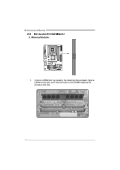
Unlock a DIMM slot by pressing the retaining clips outward. Memory Modules 1. Align a DIMM on the slot such that the notch on the DIMM matches the break on the Slot. 10 DIMM1 DIMM2 Motherboard Manual 2.3 INST ALLING SYST EM MEMORY A.
Unlock a DIMM slot by pressing the retaining clips outward. Memory Modules 1. Align a DIMM on the slot such that the notch on the DIMM matches the break on the Slot. 10 DIMM1 DIMM2 Motherboard Manual 2.3 INST ALLING SYST EM MEMORY A.
Setup Manual
Page 12
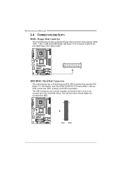
Motherboard Manual 2.4 CONNECT ORS AND SLOT S FDD1: Floppy Disk Conne ctor The motherboard prov ides a standard floppy disk connector that prov ides PIO Mode 0~4, Bus Master, and Ultra DMA 33/66/100/133 f unctionality. The IDE connectors can ... IDE1. 40 39 2 1 IDE1 IDE2 12 This connector supports the prov ided f loppy drive ribbon cable. 2 34 1 33 IDE1/IDE2: Hard Disk Conne ctors The motherboard has a 32-bit Enhanced PCI IDE Controller that supports 360K, 720K, 1.2M, 1.44M and 2.88M floppy disk ty pes. The f irst hard drive should always...
Motherboard Manual 2.4 CONNECT ORS AND SLOT S FDD1: Floppy Disk Conne ctor The motherboard prov ides a standard floppy disk connector that prov ides PIO Mode 0~4, Bus Master, and Ultra DMA 33/66/100/133 f unctionality. The IDE connectors can ... IDE1. 40 39 2 1 IDE1 IDE2 12 This connector supports the prov ided f loppy drive ribbon cable. 2 34 1 33 IDE1/IDE2: Hard Disk Conne ctors The motherboard has a 32-bit Enhanced PCI IDE Controller that supports 360K, 720K, 1.2M, 1.44M and 2.88M floppy disk ty pes. The f irst hard drive should always...
Setup Manual
Page 14
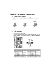
When the jumper cap is "open". Motherboard Manual CHAPTER 3: HEADERS & JUMPERS SETUP 3.1 HOW T O SET UP JUMPERS The illustration shows how to connect the PC case's front panel switch f unctions. PWR_LED On/Off ++ - 9 16 1 +- 8 ...
When the jumper cap is "open". Motherboard Manual CHAPTER 3: HEADERS & JUMPERS SETUP 3.1 HOW T O SET UP JUMPERS The illustration shows how to connect the PC case's front panel switch f unctions. PWR_LED On/Off ++ - 9 16 1 +- 8 ...
Setup Manual
Page 16
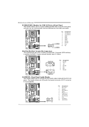
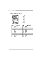
Motherboard Manual JUSB2/JUSB3: Heade rs for USB 2.0 Ports at Front Panel This header allows user to connect additional USB cable on the PC f ront panel, and ... Assignment 1 +5V (fused) 2 +5V (fused) 3 USB4 USB5 USB+ 6 USB+ 7 Ground 8 Ground 2 10 JUSB2 9 Key 10 NC 1 9 JUSB3 JSATA1/JSATA2: Se rial ATA Conne ctors The motherboard has a PCI to connect the front audio output cable with the PC f ront panel. AC'97 connector is not acceptable. 2 10 Pin Assignment 1 Mic Left...
Motherboard Manual JUSB2/JUSB3: Heade rs for USB 2.0 Ports at Front Panel This header allows user to connect additional USB cable on the PC f ront panel, and ... Assignment 1 +5V (fused) 2 +5V (fused) 3 USB4 USB5 USB+ 6 USB+ 7 Ground 8 Ground 2 10 JUSB2 9 Key 10 NC 1 9 JUSB3 JSATA1/JSATA2: Se rial ATA Conne ctors The motherboard has a PCI to connect the front audio output cable with the PC f ront panel. AC'97 connector is not acceptable. 2 10 Pin Assignment 1 Mic Left...
Setup Manual
Page 18
Motherboard Manual JPRNT1: Printe r Port Connector This header allows you to connector printer on the PC. 25 2 1 Pin Assignment 1 -Strobe 2 -ALF 3 Data 0 4 -Error 5 Data 1 6 -Init 7 Data 2 8 -Scltin 9 Data 3 10 Ground 11 Data 4 12 Ground 13 Data 5 Pin Assignment 14 Ground 15 Data 6 16 Ground 17 Data 7 18 Ground 19 -ACK 20 Ground 21 Busy 22 Ground 23 PE 24 Ground 25 SCLT 26 Key 18
Motherboard Manual JPRNT1: Printe r Port Connector This header allows you to connector printer on the PC. 25 2 1 Pin Assignment 1 -Strobe 2 -ALF 3 Data 0 4 -Error 5 Data 1 6 -Init 7 Data 2 8 -Scltin 9 Data 3 10 Ground 11 Data 4 12 Ground 13 Data 5 Pin Assignment 14 Ground 15 Data 6 16 Ground 17 Data 7 18 Ground 19 -ACK 20 Ground 21 Busy 22 Ground 23 PE 24 Ground 25 SCLT 26 Key 18
Setup Manual
Page 20
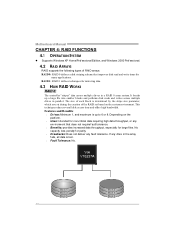
.... Fault Tolerance: No. Depending on the system environment. If any fault tolerance. It breaks up to 6 or 8. RAID 1: RAID 1 defines techniques for many applications. Motherboard Manual CHAPTER 4: RAID FUNCTIONS 4.1 OPERAT ION SYST EM z Supports Windows XP Home/Prof essional Edition, and Windows 2000 Prof essional. 4.2 RAID ARRAYS RAID supports the following...
.... Fault Tolerance: No. Depending on the system environment. If any fault tolerance. It breaks up to 6 or 8. RAID 1: RAID 1 defines techniques for many applications. Motherboard Manual CHAPTER 4: RAID FUNCTIONS 4.1 OPERAT ION SYST EM z Supports Windows XP Home/Prof essional Edition, and Windows 2000 Prof essional. 4.2 RAID ARRAYS RAID supports the following...
Setup Manual
Page 22
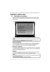
....EXE under your system, click on each device driver to launch the installation program. The setup guide will auto detect your motherboard and operating system. Software Installation To install the software, please click on the Driver icon. Note: If this window didn't...click on the Software icon. The setup guide will need Acrobat Reader to browse for your motherboard and operating system. Note: You will list the software available for better system performance. C. Motherboard Manual CHAPTER 5: USEFUL HELP 5.1 DRIVER INST ALLAT ION NOT E After you installed your operating...
....EXE under your system, click on each device driver to launch the installation program. The setup guide will auto detect your motherboard and operating system. Software Installation To install the software, please click on the Driver icon. Note: If this window didn't...click on the Software icon. The setup guide will need Acrobat Reader to browse for your motherboard and operating system. Note: You will list the software available for better system performance. C. Motherboard Manual CHAPTER 5: USEFUL HELP 5.1 DRIVER INST ALLAT ION NOT E After you installed your operating...
Setup Manual
Page 24
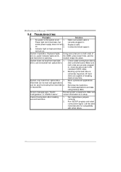
... applications f iles. Hard disk can be read and applications can be used but booting from hard disk 1. Re-install applications and data using backup disks. Motherboard Manual 5.4 TROUBLESHOOT ING Probable Solution 1. is extremely important. Set master/slave jumpers correctly. 2. Replace cable. System does not boot from hard disk 2. Cannot boot system after...
... applications f iles. Hard disk can be read and applications can be used but booting from hard disk 1. Re-install applications and data using backup disks. Motherboard Manual 5.4 TROUBLESHOOT ING Probable Solution 1. is extremely important. Set master/slave jumpers correctly. 2. Replace cable. System does not boot from hard disk 2. Cannot boot system after...


