
User Guide
Page 1
... make sure that could result in a builtin installation unless proper ventilation is provided. 5 Never push objects of any kind into a grounding-type power outlet. This product should not be placed in a fire or electrical shock. Never spill liquid of any kind on the product. 6 This.... The product may touch dangerous voltage points or short out parts that the total amperage rating of all equipment plugged into the main AC power outlet does not exceed 15 amps. 9 Unplug your electrician to use . 2 Follow all of these instructions carefully. 1 Save these openings...
... make sure that could result in a builtin installation unless proper ventilation is provided. 5 Never push objects of any kind into a grounding-type power outlet. This product should not be placed in a fire or electrical shock. Never spill liquid of any kind on the product. 6 This.... The product may touch dangerous voltage points or short out parts that the total amperage rating of all equipment plugged into the main AC power outlet does not exceed 15 amps. 9 Unplug your electrician to use . 2 Follow all of these instructions carefully. 1 Save these openings...
User Guide
Page 2
...product does not operate normally, adjust only those controls that are covered by the operating instructions. Improper adjustment of the following precautions: 1 The power supply cord must be unplugged before the main system unit cover is removed. (Separe le cordon d'alimentation et puis enleve le couvercle.) 2 ...Once removed, the cover must be replaced and screwed in position before the power supply cord is damaged or frayed. 2 If liquid has been spilled into the product. 3 If the product has been exposed to rain or ...
...product does not operate normally, adjust only those controls that are covered by the operating instructions. Improper adjustment of the following precautions: 1 The power supply cord must be unplugged before the main system unit cover is removed. (Separe le cordon d'alimentation et puis enleve le couvercle.) 2 ...Once removed, the cover must be replaced and screwed in position before the power supply cord is damaged or frayed. 2 If liquid has been spilled into the product. 3 If the product has been exposed to rain or ...
User Guide
Page 8
... PowerDVD 6-1 How to Run the PowerDVD 6-1 Buttons of the PowerDVD 6-2 Appendix A. Approval Statements Battery Warning Instruction B-1 Fuse Warning Instruction B-1 Laser Product ...B-2 viii Solving Common Problems Power ...A-1 Hard Disk Drive ...A-1 Optical Drive ...A-2 Audio ...A-2 Floppy Disk Drive A-3 Display & Monitor A-3 Keyboard ...A-4 Mouse ...A-4 Appendix B.
... PowerDVD 6-1 How to Run the PowerDVD 6-1 Buttons of the PowerDVD 6-2 Appendix A. Approval Statements Battery Warning Instruction B-1 Fuse Warning Instruction B-1 Laser Product ...B-2 viii Solving Common Problems Power ...A-1 Hard Disk Drive ...A-1 Optical Drive ...A-2 Audio ...A-2 Floppy Disk Drive A-3 Display & Monitor A-3 Keyboard ...A-4 Mouse ...A-4 Appendix B.
User Guide
Page 9
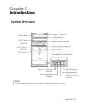
Introduction System Overview Optical drive Optical drive (optional) USB connector (optional) Power button Emergency eject hole Load/Eject button Floppy disk drive(optional) Media reader slots(optional) Power indicator Hard disk drive access indicator IEEE 1394 connectors (optional) USB 2.0 connectors (optional) Headphone jack Microphone jack USB 2.0 connectors (optional) NOTE Chapter 1 Your optical drives may differ from the illustrations described in this user's guide. Introduction 1-1
Introduction System Overview Optical drive Optical drive (optional) USB connector (optional) Power button Emergency eject hole Load/Eject button Floppy disk drive(optional) Media reader slots(optional) Power indicator Hard disk drive access indicator IEEE 1394 connectors (optional) USB 2.0 connectors (optional) Headphone jack Microphone jack USB 2.0 connectors (optional) NOTE Chapter 1 Your optical drives may differ from the illustrations described in this user's guide. Introduction 1-1
User Guide
Page 11
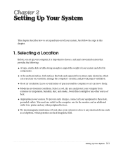
... this chapter. 1. A flat and hard surface. Soft surfaces like beds and carpeted floors attract static electricity, which generates an electromagnetic field. Moderate environment conditions. Appropriate power sources. Setting Up Your System 2-1 Good air circulation. Select a cool, dry area and protect your system too close to three-hole, grounded outlets. To prevent...
... this chapter. 1. A flat and hard surface. Soft surfaces like beds and carpeted floors attract static electricity, which generates an electromagnetic field. Moderate environment conditions. Appropriate power sources. Setting Up Your System 2-1 Good air circulation. Select a cool, dry area and protect your system too close to three-hole, grounded outlets. To prevent...
User Guide
Page 12
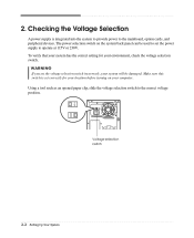
... setting for your computer. Voltage selection switch 2-2 Setting Up Your System Make sure this switch is integrated into the system to provide power to operate at 115V or 230V. The power selection switch on your location before turning on the system back panel can be damaged. Using a tool such as an opened...
... setting for your computer. Voltage selection switch 2-2 Setting Up Your System Make sure this switch is integrated into the system to provide power to operate at 115V or 230V. The power selection switch on your location before turning on the system back panel can be damaged. Using a tool such as an opened...
User Guide
Page 13
3. This will prevent damage to plug the power cord into the system before plugging it is left unattended and unused for long periods of time, unplug the computer and other devices from the ... your computer and other devices due to the Setting Up Your Computer. Connecting Your Peripheral Devices To connect the peripheral devices, refer to lighting and power line surges. Setting Up Your System 2-3
3. This will prevent damage to plug the power cord into the system before plugging it is left unattended and unused for long periods of time, unplug the computer and other devices from the ... your computer and other devices due to the Setting Up Your Computer. Connecting Your Peripheral Devices To connect the peripheral devices, refer to lighting and power line surges. Setting Up Your System 2-3
User Guide
Page 14
To start Windows, remove the Restore CD and restart the computer. Turn off your computer. 2. Press the power button on the monitor, and any other peripheral devices connected to turn on your information and close all application programs you use. 2. In this case, ...
To start Windows, remove the Restore CD and restart the computer. Turn off your computer. 2. Press the power button on the monitor, and any other peripheral devices connected to turn on your information and close all application programs you use. 2. In this case, ...
User Guide
Page 23
... computer from its internal components. To remove the cover, follow these steps: 1. Then disconnect any of the procedures described in your system to access its power source and from the back panel. Removing the Cover You need to remove the cover of all, disconnect the... power cable from the electrical outlet and from any telecommunications links, networks, or modems before performing any cables connected to the computer. NOTE Turn off the ...
... computer from its internal components. To remove the cover, follow these steps: 1. Then disconnect any of the procedures described in your system to access its power source and from the back panel. Removing the Cover You need to remove the cover of all, disconnect the... power cable from the electrical outlet and from any telecommunications links, networks, or modems before performing any cables connected to the computer. NOTE Turn off the ...
User Guide
Page 30
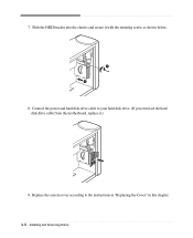
Replace the system cover according to your hard disk drive. (If you removed the hard disk drive cable from the motherboard, replace it with the retaining screw, as shown below. 8. Connect the power and hard disk drive cable to the instructions in "Replacing the Cover" in this chapter. 4-8 Installing and Removing Drives 7. Slide the HDD bracket into the chassis and secure it .) 9.
Replace the system cover according to your hard disk drive. (If you removed the hard disk drive cable from the motherboard, replace it with the retaining screw, as shown below. 8. Connect the power and hard disk drive cable to the instructions in "Replacing the Cover" in this chapter. 4-8 Installing and Removing Drives 7. Slide the HDD bracket into the chassis and secure it .) 9.
User Guide
Page 32
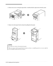
Remove the screws securing the optical drive. Remove the front panel from the system. 5. And then slide the optical drive from the chassis by pulling the front panel. When you remove the front panel from the front panel. 4-10 Installing and Removing Drives 4. NOTES Be careful, not to split the power and LED cables from the chassis, you have to carefully apart the cover not to bent or break the front panel.
Remove the screws securing the optical drive. Remove the front panel from the system. 5. And then slide the optical drive from the chassis by pulling the front panel. When you remove the front panel from the front panel. 4-10 Installing and Removing Drives 4. NOTES Be careful, not to split the power and LED cables from the chassis, you have to carefully apart the cover not to bent or break the front panel.
User Guide
Page 34
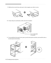
Connect the power and interface cables to the computer case with two screws. 10. Secondary EIDE connector 11. 9. To reassemble the front panel to the system, press the front panel toward the system until the tabs on the front panel click into the bay and secure it to the device installed. Slide the device into place. 4-12 Installing and Removing Drives
Connect the power and interface cables to the computer case with two screws. 10. Secondary EIDE connector 11. 9. To reassemble the front panel to the system, press the front panel toward the system until the tabs on the front panel click into the bay and secure it to the device installed. Slide the device into place. 4-12 Installing and Removing Drives
User Guide
Page 35
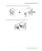
Installing and Removing Drives 4-13 12. Connect the power, audio, and interface cables to the system with screws. 13. Slide the optical drive into the bay and secure it to the optical drive.
Installing and Removing Drives 4-13 12. Connect the power, audio, and interface cables to the system with screws. 13. Slide the optical drive into the bay and secure it to the optical drive.
User Guide
Page 42
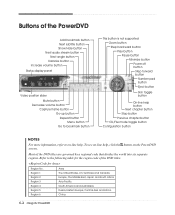
... button Repeat button Menu button Go to bookmark button This button is not supported Zoom button Step backward button Play button Pause button Minimize button Power off button Step forward button Number pad button Eject button Skin toggle button On-line help . To see on-line help, click the button on...
... button Repeat button Menu button Go to bookmark button This button is not supported Zoom button Step backward button Play button Pause button Minimize button Power off button Step forward button Number pad button Eject button Skin toggle button On-line help . To see on-line help, click the button on...
User Guide
Page 43
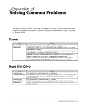
..., click the Start button, and then click Help and Support.) The files stored on the computer, refer to the followings: Unplug the power cord to turn on your hard disk may be fragmented. If it before calling a technician if a problem occurs. Solving Common Problems This... chapter instructs you how to deal with the problems you press the power button. Wall outlet is listed first, followed by running Disk Defragmenter. (For more information,refer to the Windows Help. Check for complete ...
..., click the Start button, and then click Help and Support.) The files stored on the computer, refer to the followings: Unplug the power cord to turn on your hard disk may be fragmented. If it before calling a technician if a problem occurs. Solving Common Problems This... chapter instructs you how to deal with the problems you press the power button. Wall outlet is listed first, followed by running Disk Defragmenter. (For more information,refer to the Windows Help. Check for complete ...
User Guide
Page 45
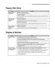
...can't write to a diskette Floppy disk drive can't read the diskette Solution Diskette is not write-protected. Solving Common Problems A-3 Make sure the power cord is not properly connected to cover the hole. You have a screen blanking utility installed or your mouse. Press any key or move your... computer entered power management mode. Your current screen will reappear. Or click the right mouse button on the monitor. Remove the write-protection or use the ...
...can't write to a diskette Floppy disk drive can't read the diskette Solution Diskette is not write-protected. Solving Common Problems A-3 Make sure the power cord is not properly connected to cover the hole. You have a screen blanking utility installed or your mouse. Press any key or move your... computer entered power management mode. Your current screen will reappear. Or click the right mouse button on the monitor. Remove the write-protection or use the ...
User Guide
Page 47
... or equivalent type recommended by the manufacturer. Vorsicht Vor jeder service-arbeit netzstecker ziehen! Discard used batteries according to an earthed socket outlet. Disconnect input power before servicing. Apparaten skall anslutas till jordat nätuttag. Replace battery only with same type and rating of explosion. Vorsicht Explosionsgefahr bei unsachgemäß...
... or equivalent type recommended by the manufacturer. Vorsicht Vor jeder service-arbeit netzstecker ziehen! Discard used batteries according to an earthed socket outlet. Disconnect input power before servicing. Apparaten skall anslutas till jordat nätuttag. Replace battery only with same type and rating of explosion. Vorsicht Explosionsgefahr bei unsachgemäß...
User Guide
Page 48
.... Pour toute intervention, adressez-vous à un personnel qualifié. To reduce the risk of procedures other openings to look into the inside . When the power switch is no hazardous LASER radiation with International Electrotechnical Commission (IEC) Publication 825]. Caution The laser used in hazardous radiation exposure. Do not open the...
.... Pour toute intervention, adressez-vous à un personnel qualifié. To reduce the risk of procedures other openings to look into the inside . When the power switch is no hazardous LASER radiation with International Electrotechnical Commission (IEC) Publication 825]. Caution The laser used in hazardous radiation exposure. Do not open the...


