Service Guide
Page 7
...7 Indicators 9 TouchPad Basics 10 Using the Keyboard 11 Lock Keys and embedded numeric keypad 11 Windows Keys 12 Hot Keys 13 Special Key 14 Hardware Specifications and Configurations 15 System Utilities 21 BIOS Setup Utility 21 Navigating the BIOS Utility 21 eMachines G630/G430 BIOS 22 Information 22 Main 23 Security 24 Boot 27 Exit 28 BIOS Flash Utilities 29 DOS Flash Utility 30 WinFlash Utility 31 Remove HDD/BIOS Password Utilities 32 Machine Disassembly and Replacement 37 Disassembly Requirements 37 Pre-disassembly Instructions 38 Disassembly Process 38 External...
...7 Indicators 9 TouchPad Basics 10 Using the Keyboard 11 Lock Keys and embedded numeric keypad 11 Windows Keys 12 Hot Keys 13 Special Key 14 Hardware Specifications and Configurations 15 System Utilities 21 BIOS Setup Utility 21 Navigating the BIOS Utility 21 eMachines G630/G430 BIOS 22 Information 22 Main 23 Security 24 Boot 27 Exit 28 BIOS Flash Utilities 29 DOS Flash Utility 30 WinFlash Utility 31 Remove HDD/BIOS Password Utilities 32 Machine Disassembly and Replacement 37 Disassembly Requirements 37 Pre-disassembly Instructions 38 Disassembly Process 38 External...
Service Guide
Page 8
... Replacing the Hard Disk Drive Module 110 Replacing the WLAN Module 112 Replacing the DIMM Modules 112 Replacing the ODD Module 113 Replacing the Lower Covers 113 Replacing the SD Dummy Card 114 Replacing the Battery 115 Troubleshooting 117 Common Problems 117 Power On Issue 118 No Display Issue 119 Random Loss of BIOS Settings 120 LCD Failure 121 Built-In Keyboard Failure 121 TouchPad Failure 122 Internal Speaker Failure 122 HDD Not Operating Correctly 124 ODD Failure 125 Wireless Function...
... Replacing the Hard Disk Drive Module 110 Replacing the WLAN Module 112 Replacing the DIMM Modules 112 Replacing the ODD Module 113 Replacing the Lower Covers 113 Replacing the SD Dummy Card 114 Replacing the Battery 115 Troubleshooting 117 Common Problems 117 Power On Issue 118 No Display Issue 119 Random Loss of BIOS Settings 120 LCD Failure 121 Built-In Keyboard Failure 121 TouchPad Failure 122 Internal Speaker Failure 122 HDD Not Operating Correctly 124 ODD Failure 125 Wireless Function...
Service Guide
Page 14
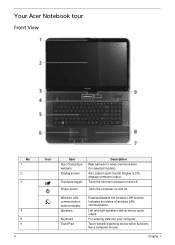
... LAN communication. Chapter 1 Turns the computer on and off . For entering data into your computer. Touch-sensitive pointing device which functions like a computer mouse. Turns the internal touchpad on and off . Your Acer Notebook tour Front View No. 1 2 3 4 5 6 4 Icon Item Acer Crystal Eye webcam Display screen Touchpad toggle Power button Description Web camera for video communication (for selected models). Wireless LAN communication button/indicator Speakers Keyboard TouchPad Enables/disables the wireless LAN function. Left and right speakers deliver stereo audio...
... LAN communication. Chapter 1 Turns the computer on and off . For entering data into your computer. Touch-sensitive pointing device which functions like a computer mouse. Turns the internal touchpad on and off . Your Acer Notebook tour Front View No. 1 2 3 4 5 6 4 Icon Item Acer Crystal Eye webcam Display screen Touchpad toggle Power button Description Web camera for video communication (for selected models). Wireless LAN communication button/indicator Speakers Keyboard TouchPad Enables/disables the wireless LAN function. Left and right speakers deliver stereo audio...
Service Guide
Page 15
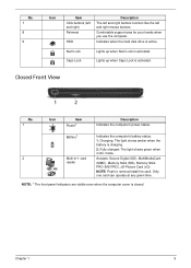
... cover is activated. Lights up when Num Lock is active. Closed Front View No. 1 Icon Item Power1 Description Indicates the computer's power status. NOTE: Push to remove/install the card. Comfortable support area for your hands when you use the computer. Fully charged: The light shows green when in AC mode. 2 Multi-in-1 card Accepts: Secure Digital (SD), MultiMediaCard reader (MMC), Memory Stick (MS), Memory Stick PRO (MS PRO), xD-Picture Card...
... cover is activated. Lights up when Num Lock is active. Closed Front View No. 1 Icon Item Power1 Description Indicates the computer's power status. NOTE: Push to remove/install the card. Comfortable support area for your hands when you use the computer. Fully charged: The light shows green when in AC mode. 2 Multi-in-1 card Accepts: Secure Digital (SD), MultiMediaCard reader (MMC), Memory Stick (MS), Memory Stick PRO (MS PRO), xD-Picture Card...
Service Guide
Page 23
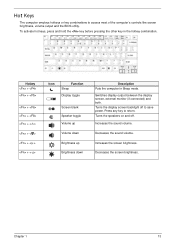
Turns the display screen backlight off . Decreases the sound volume. Decreases the screen brightness. Chapter 1 13 Switches display output between the display screen, external monitor (if connected) and both. Press any key to save power. Increases the sound volume. Hot Keys The computer employs hotkeys or key combinations to access most of the computer's controls like screen brightness, volume output and the BIOS utility. Hotkey + + + + + < > + < > + < > + < > Icon Function Sleep Display toggle Screen blank Speaker toggle Volume up Volume down Brightness up ...
Turns the display screen backlight off . Decreases the sound volume. Decreases the screen brightness. Chapter 1 13 Switches display output between the display screen, external monitor (if connected) and both. Press any key to save power. Increases the sound volume. Hot Keys The computer employs hotkeys or key combinations to access most of the computer's controls like screen brightness, volume output and the BIOS utility. Hotkey + + + + + < > + < > + < > + < > Icon Function Sleep Display toggle Screen blank Speaker toggle Volume up Volume down Brightness up ...
Service Guide
Page 31
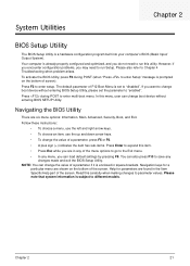
... menu, user can load default settings by pressing F9. Press during POST (when "Press to enter Setup" message is already properly configured and optimized, and you can change boot device without entering BIOS SETUP Utility. To activate the BIOS Utility, press F2 during POST to the Exit menu. • In any changes made and exit the BIOS Setup Utility. Navigation keys for parameters are six menu options: Information, Main, Advanced, Security, Boot, and Exit. Follow these instructions...
... menu, user can load default settings by pressing F9. Press during POST (when "Press to enter Setup" message is already properly configured and optimized, and you can change boot device without entering BIOS SETUP Utility. To activate the BIOS Utility, press F2 during POST to the Exit menu. • In any changes made and exit the BIOS Setup Utility. Navigation keys for parameters are six menu options: Information, Main, Advanced, Security, Boot, and Exit. Follow these instructions...

Service Guide
Page 32
... F5/F6 Change Values F9 Setup Defaults Select Menu Enter Select Sub-Menu F10 Save and Exit NOTE: The screen above is an identifier standard used in the system. This field shows the model name of the Optical device installed in software construction, standardized by the Open Software Foundation (OSF) as part of the Distributed Computing Environment (DCE). 22 Chapter 2 This field displays the VGA firmware version...
... F5/F6 Change Values F9 Setup Defaults Select Menu Enter Select Sub-Menu F10 Save and Exit NOTE: The screen above is an identifier standard used in the system. This field shows the model name of the Optical device installed in software construction, standardized by the Open Software Foundation (OSF) as part of the Distributed Computing Environment (DCE). 22 Chapter 2 This field displays the VGA firmware version...
Service Guide
Page 35
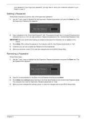
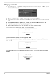
... Enter key. Use the ↑ and ↓ keys to enable the Password on the screen. 3. The password length can opt to highlight the Set Supervisor Password parameter and press the Enter key. After setting the password, the computer sets the User Password parameter to save the changes and exit the BIOS Setup Utility. When you have to return your notebook computer to your dealer to "Clear". 4. Type the current password in the Enter New Password and Confirm New Password fields. Use...
... Enter key. Use the ↑ and ↓ keys to enable the Password on the screen. 3. The password length can opt to highlight the Set Supervisor Password parameter and press the Enter key. After setting the password, the computer sets the User Password parameter to save the changes and exit the BIOS Setup Utility. When you have to return your notebook computer to your dealer to "Clear". 4. Type the current password in the Enter New Password and Confirm New Password fields. Use...
Service Guide
Page 36
... boot parameter. 6. Changing a Password 1. The Set Password box appears. Press Enter. Type the current password in the Enter Current Password field and press Enter. 3. When you are done, press F10 to highlight the Set Supervisor Password parameter and press the Enter key. Setup Notice Changes have been saved. [Continue] The password setting is OK, the screen will display the following message. Use the ↑ and ↓ keys to save the changes and exit the BIOS Setup Utility...
... boot parameter. 6. Changing a Password 1. The Set Password box appears. Press Enter. Type the current password in the Enter Current Password field and press Enter. 3. When you are done, press F10 to highlight the Set Supervisor Password parameter and press the Enter key. Setup Notice Changes have been saved. [Continue] The password setting is OK, the screen will display the following message. Use the ↑ and ↓ keys to save the changes and exit the BIOS Setup Utility...
Service Guide
Page 127
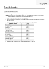
... much detail as a guide for computer problems. NOTE: The diagnostic tests are intended to re-create the failure by running the diagnostic test or by repeating the same operation. 3. Symptoms (Verified) Go To Power On Issue Page 118 No Display Issue Page 119 LCD Failure Page 121 Internal Keyboard Failure Page 121 TouchPad Failure Page 122 Internal Speaker Failure Page 122...
... much detail as a guide for computer problems. NOTE: The diagnostic tests are intended to re-create the failure by running the diagnostic test or by repeating the same operation. 3. Symptoms (Verified) Go To Power On Issue Page 118 No Display Issue Page 119 LCD Failure Page 121 Internal Keyboard Failure Page 121 TouchPad Failure Page 122 Internal Speaker Failure Page 122...
Service Guide
Page 129
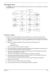
... external display, see "Disassembly Process" on page 38). 8. If the computer boots correctly, add the devices one by one at a time to correct the problem. Reseat the memory modules. 7. Make sure that the internal display is by removing the power cable and battery and holding down the power button for specific model procedures. 2. Reference Product pages for 10 seconds. Remove any stored power by pressing Fn+F5 (on page 183. Remove the drives...
... external display, see "Disassembly Process" on page 38). 8. If the computer boots correctly, add the devices one by one at a time to correct the problem. Reseat the memory modules. 7. Make sure that the internal display is by removing the power cable and battery and holding down the power button for specific model procedures. 2. Reference Product pages for 10 seconds. Remove any stored power by pressing Fn+F5 (on page 183. Remove the drives...
Service Guide
Page 130
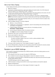
... BIOS, the drive may reduce display brightness. Run a complete virus scan using up-to-date software to ensure the computer is correctly configured: a. If permanent vertical/horizontal lines or dark spots display in the same locations on page 38. 3. NOTE: Ensure that : • The device is more than one year old, replace the CMOS battery. 2. Check the display resolution is virus free. 3. Roll back the video driver...
... BIOS, the drive may reduce display brightness. Run a complete virus scan using up-to-date software to ensure the computer is correctly configured: a. If permanent vertical/horizontal lines or dark spots display in the same locations on page 38. 3. NOTE: Ensure that : • The device is more than one year old, replace the CMOS battery. 2. Check the display resolution is virus free. 3. Roll back the video driver...
Service Guide
Page 133
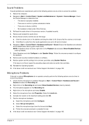
..., see "Online Support Information" on the Recording tab and select Show Disabled Devices (clear by default). 7. Navigate to the maximum setting and click OK. 7. Select the Levels tab. 6. Reboot the computer. 2. b. Increase the volume to Start´ Control Panel´ Hardware and Sound´ Sound and select the Recording tab. 2. Select the microphone and click Configure. Select the microphone type from a known good date using System Restore. Sound Problems If sound problems are experienced...
..., see "Online Support Information" on the Recording tab and select Show Disabled Devices (clear by default). 7. Navigate to the maximum setting and click OK. 7. Select the Levels tab. 6. Reboot the computer. 2. b. Increase the volume to Start´ Control Panel´ Hardware and Sound´ Sound and select the Recording tab. 2. Select the microphone and click Configure. Select the microphone type from a known good date using System Restore. Sound Problems If sound problems are experienced...
Service Guide
Page 134
... Windows Check Disk by entering chkdsk /r from a known good date using up-to-date software to the operating system DVD. See "Disassembly Process" on the Boot menu. 6. When prompted, press any recently added hardware and associated software. 8. h. Ensure all external devices. 2. The System Recovery Options screen displays. d. Run the Windows 7 Startup Repair Utility: a. The Install Windows screen displays. i. Check the BIOS settings are required. Select the appropriate operating system, and click Next. If the issue is virus free. 3. Run the Windows Memory...
... Windows Check Disk by entering chkdsk /r from a known good date using up-to-date software to the operating system DVD. See "Disassembly Process" on the Boot menu. 6. When prompted, press any recently added hardware and associated software. 8. h. Ensure all external devices. 2. The System Recovery Options screen displays. d. Run the Windows 7 Startup Repair Utility: a. The Install Windows screen displays. i. Check the BIOS settings are required. Select the appropriate operating system, and click Next. If the issue is virus free. 3. Run the Windows Memory...
Service Guide
Page 136
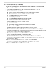
... to correct the problem. 1. Check that the disc is not removed from the drop down list. b. Navigate to Start´ Control Panel´ Hardware and Sound´ AutoPlay. Select the Recording tab. If using different software, refer to Start´ Control Panel´ System and Maintenance´ System´ Device Manager. 126 Chapter 4 Navigate to the software's user manual. Double-click lDE ATA/ATAPI controllers. Double-click DVD/CD-ROM drives. c. Check that the...
... to correct the problem. 1. Check that the disc is not removed from the drop down list. b. Navigate to Start´ Control Panel´ Hardware and Sound´ AutoPlay. Select the Recording tab. If using different software, refer to Start´ Control Panel´ System and Maintenance´ System´ Device Manager. 126 Chapter 4 Navigate to the software's user manual. Double-click lDE ATA/ATAPI controllers. Double-click DVD/CD-ROM drives. c. Check that the...
Service Guide
Page 137
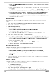
... ATAPI Model Name field on the drive, motherboard, and cable connections. Reseat the drive ensuring and all cables are connected correctly. 5. Replace the ODD. Drive Read Failure If discs cannot be replaced. 4. Remove and clean the failed disc. 2. d. Test the drive using other ATA Devices shown if applicable. Play a DVD movie f. Turn off the power and remove the cover to inspect the connections to enter the BIOS Utility. 2. a. Check for the other discs. Replace the ODD. See "Disassembly Process...
... ATAPI Model Name field on the drive, motherboard, and cable connections. Reseat the drive ensuring and all cables are connected correctly. 5. Replace the ODD. Drive Read Failure If discs cannot be replaced. 4. Remove and clean the failed disc. 2. d. Test the drive using other ATA Devices shown if applicable. Play a DVD movie f. Turn off the power and remove the cover to inspect the connections to enter the BIOS Utility. 2. a. Check for the other discs. Replace the ODD. See "Disassembly Process...
Service Guide
Page 139
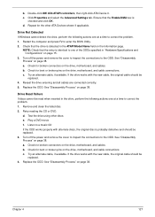
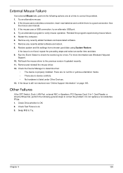
... not resolved, see Windows Help and Support. 10. Check Test Fixture is a good connection. Swap M/B to the previous version if updated recently. 11. Chapter 4 129 See the mouse user manual. 3. Restart the computer. 6. If the mouse uses a wireless connection, insert new batteries and confirm there is ok. 3. Other Failures If the CRT Switch, Dock, LAN Port, external MIC or Speakers, PCI Express Card, 5-in-1 Card Reader or Volume Wheel fail, perform...
... not resolved, see Windows Help and Support. 10. Check Test Fixture is a good connection. Swap M/B to the previous version if updated recently. 11. Chapter 4 129 See the mouse user manual. 3. Restart the computer. 6. If the mouse uses a wireless connection, insert new batteries and confirm there is ok. 3. Other Failures If the CRT Switch, Dock, LAN Port, external MIC or Speakers, PCI Express Card, 5-in-1 Card Reader or Volume Wheel fail, perform...
Service Guide
Page 140
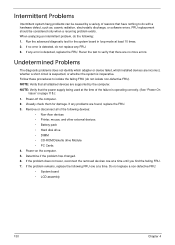
... changed. 6. When analyzing an intermittent problem, do not isolate non-defective FRU). Rerun the test to verify that have nothing to isolate the failing FRU (do the following: 1. If the problem remains, replace the following devices: • Non-Acer devices • Printer, mouse, and other external devices • Battery pack • Hard disk drive • DIMM • CD-ROM/Diskette drive Module • PC Cards 4. If any problems...
... changed. 6. When analyzing an intermittent problem, do not isolate non-defective FRU). Rerun the test to verify that have nothing to isolate the failing FRU (do the following: 1. If the problem remains, replace the following devices: • Non-Acer devices • Printer, mouse, and other external devices • Battery pack • Hard disk drive • DIMM • CD-ROM/Diskette drive Module • PC Cards 4. If any problems...
Service Guide
Page 195
... Onboard Device Configuration 25 Save and Exit 28 Security 24 System Security 28 Board Layout Top View 137 brightness hotkeys 13 C Camera Module Removing 77 Replacing 90 caps lock on indicator 5, 9 Common Problems 118 computer on indicator 5, 9 CPU Removing 74 Replacing 93 CPU Fan Removing 72 Replacing 94 D DIMM Modules Removing 45 Replacing 112 Display 3 display hotkeys 13 E EasyTouch Failure 128 Euro 14 External Module Disassembly Flowchart 39 F Features 1 Flash Utility 29 FPC Cable Removing 80 FRU (Field Replaceable Unit) List 143 H Hard Disk Drive Removing 48 Replacing 110 HDTV Switch...
... Onboard Device Configuration 25 Save and Exit 28 Security 24 System Security 28 Board Layout Top View 137 brightness hotkeys 13 C Camera Module Removing 77 Replacing 90 caps lock on indicator 5, 9 Common Problems 118 computer on indicator 5, 9 CPU Removing 74 Replacing 93 CPU Fan Removing 72 Replacing 94 D DIMM Modules Removing 45 Replacing 112 Display 3 display hotkeys 13 E EasyTouch Failure 128 Euro 14 External Module Disassembly Flowchart 39 F Features 1 Flash Utility 29 FPC Cable Removing 80 FRU (Field Replaceable Unit) List 143 H Hard Disk Drive Removing 48 Replacing 110 HDTV Switch...
Service Guide
Page 196
... Module Removing 62 Lower Covers Removing 42 Replacing 113 M Main Unit Disassembly Flowchart 50 Mainboard Removing 68 Replacing 95 media access on indicator 5, 9 Memory Removing 45 Replacing 112 Memory Check 118 Model Definition 156 N No Display Issue 119 num lock on indicator 5, 9 O ODD Failure 125 Online Support Information 183 Optical Disk Drive Replacing 113 186 Optical Drive Module Removing 43 P Panel 4 Bottom 7 PC Card 9 Power Board Removing 61 Replacing 100 Power On Failure 118 R Right Speaker Module Removing 64 Replacing 98 RTC Battery Removing 69 S SD Dummy Card Removing 41 Replacing...
... Module Removing 62 Lower Covers Removing 42 Replacing 113 M Main Unit Disassembly Flowchart 50 Mainboard Removing 68 Replacing 95 media access on indicator 5, 9 Memory Removing 45 Replacing 112 Memory Check 118 Model Definition 156 N No Display Issue 119 num lock on indicator 5, 9 O ODD Failure 125 Online Support Information 183 Optical Disk Drive Replacing 113 186 Optical Drive Module Removing 43 P Panel 4 Bottom 7 PC Card 9 Power Board Removing 61 Replacing 100 Power On Failure 118 R Right Speaker Module Removing 64 Replacing 98 RTC Battery Removing 69 S SD Dummy Card Removing 41 Replacing...


