
User Guide
Page 7
...or cord is a remote risk of fire replace only with general waste. ONLY qualified service personnel should service or disassemble this device during a thunderstorm. XGS4700-48F User's Guide 7 Safety Warnings Safety Warnings • Do NOT use this product near water, for example, in Europe). • Do NOT ... on the device. • Do NOT install, use, or service this device. Contact your device. WEEE stands for example, 110V AC in North America or 230V AC in a wet basement or near a swimming pool. • Do NOT expose your device to dampness, dust or corrosive liquids. •...
...or cord is a remote risk of fire replace only with general waste. ONLY qualified service personnel should service or disassemble this device during a thunderstorm. XGS4700-48F User's Guide 7 Safety Warnings Safety Warnings • Do NOT use this product near water, for example, in Europe). • Do NOT ... on the device. • Do NOT install, use, or service this device. Contact your device. WEEE stands for example, 110V AC in North America or 230V AC in a wet basement or near a swimming pool. • Do NOT expose your device to dampness, dust or corrosive liquids. •...
User Guide
Page 12
... Panel ...46 3.2.1 Removing and Installing the Fan Module 47 3.2.2 Uplink Module ...48 3.2.3 Rear Panel Connections 48 3.2.4 Management Port ...49 3.2.5 Power Connector ...49 3.3 Power Connection ...49 3.3.1 AC Power Connections 50 3.3.2 DC Power Connections 50 3.3.3 Procedure to Turn on the Switch Power 51 3.3.4 Disconnecting the Power 51 3.4 LEDs ...52 Chapter 4 The Web Configurator... ...71 6.1 How to Use DHCP Snooping on the Switch 71 6.2 How to Use DHCP Relay on the Switch 75 6.2.1 DHCP Relay Tutorial Introduction 75 12 XGS4700-48F User's Guide
... Panel ...46 3.2.1 Removing and Installing the Fan Module 47 3.2.2 Uplink Module ...48 3.2.3 Rear Panel Connections 48 3.2.4 Management Port ...49 3.2.5 Power Connector ...49 3.3 Power Connection ...49 3.3.1 AC Power Connections 50 3.3.2 DC Power Connections 50 3.3.3 Procedure to Turn on the Switch Power 51 3.3.4 Disconnecting the Power 51 3.4 LEDs ...52 Chapter 4 The Web Configurator... ...71 6.1 How to Use DHCP Snooping on the Switch 71 6.2 How to Use DHCP Relay on the Switch 75 6.2.1 DHCP Relay Tutorial Introduction 75 12 XGS4700-48F User's Guide

User Guide
Page 36
... other cables or wiring. Warning! Figure 8 Switch Frame Ground Frame Ground 2.4 Power Module Installation There is on the power slot cover and remove it . 36 XGS4700-48F User's Guide Connect the frame ground before you how to install a second power module or remove the power module. 2.4.1 Installing a Power Module Use the following...
... other cables or wiring. Warning! Figure 8 Switch Frame Ground Frame Ground 2.4 Power Module Installation There is on the power slot cover and remove it . 36 XGS4700-48F User's Guide Connect the frame ground before you how to install a second power module or remove the power module. 2.4.1 Installing a Power Module Use the following...
User Guide
Page 38
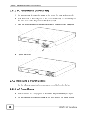
Chapter 2 Hardware Installation and Connection 2.4.1.2 DC Power Module (DCP4700-48F) 1 Use a screwdriver to loosen the screw on the power slot cover and remove it. 2 Grab the handle of the front panel of the power module ... backplane. 4 Tighten the screw. 2.4.2 Removing a Power Module Use the following procedure to remove a power module from the Switch. 2.4.2.1 AC Power Module 1 Refer to Section 3.3.4 on page 51 to disconnect the power before you begin. 2 Use a screwdriver to loosen the screw on the front panel of the power module. 38 XGS4700-48F User's Guide
Chapter 2 Hardware Installation and Connection 2.4.1.2 DC Power Module (DCP4700-48F) 1 Use a screwdriver to loosen the screw on the power slot cover and remove it. 2 Grab the handle of the front panel of the power module ... backplane. 4 Tighten the screw. 2.4.2 Removing a Power Module Use the following procedure to remove a power module from the Switch. 2.4.2.1 AC Power Module 1 Refer to Section 3.3.4 on page 51 to disconnect the power before you begin. 2 Use a screwdriver to loosen the screw on the front panel of the power module. 38 XGS4700-48F User's Guide
User Guide
Page 46
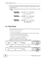
... module (A) • Two optional slot (B and C) for installing EM-422 or EM-412 uplink modules • An RJ-45 out-of the AC and DC power input model switches. Figure 15 Daisy-chaining an External Alarm Sensor to the first switch, as those you used when connecting to...receptacle (G) • A power switch (H) (DC power module only) Figure 16 Rear Panel with an AC Power Module Installed A B C D E Figure 17 Rear Panel with a DC Power Module Installed FG HG 46 XGS4700-48F User's Guide Chapter 3 Hardware Overview 2 When daisy-chaining further Switches ensure that the signal output pins...
... module (A) • Two optional slot (B and C) for installing EM-422 or EM-412 uplink modules • An RJ-45 out-of the AC and DC power input model switches. Figure 15 Daisy-chaining an External Alarm Sensor to the first switch, as those you used when connecting to...receptacle (G) • A power switch (H) (DC power module only) Figure 16 Rear Panel with an AC Power Module Installed A B C D E Figure 17 Rear Panel with a DC Power Module Installed FG HG 46 XGS4700-48F User's Guide Chapter 3 Hardware Overview 2 When daisy-chaining further Switches ensure that the signal output pins...
User Guide
Page 49
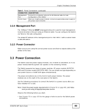
... power module fails the system can configure the Switch via Telnet or the web configurator. The power connections are using an Ethernet cable. DC/AC Input After you are on your power source or install both types simutaneously. You can operate on page 455, and make sure you install...of the rear panel of each power module. Observe the following procedures to connect the Switch to this port using an appropriate power source. XGS4700-48F User's Guide 49 The Switch supports two types of the Switch. The default IP address of the management port is redundant, so if one...
... power module fails the system can configure the Switch via Telnet or the web configurator. The power connections are using an Ethernet cable. DC/AC Input After you are on your power source or install both types simutaneously. You can operate on page 455, and make sure you install...of the rear panel of each power module. Observe the following procedures to connect the Switch to this port using an appropriate power source. XGS4700-48F User's Guide 49 The Switch supports two types of the Switch. The default IP address of the management port is redundant, so if one...
User Guide
Page 50
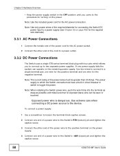
... Connections 1 Connect the female end of the power cord to the AC power socket. 2 Connect the other end of a power wire to the Switch's -48V (input) pin and tighten the captive screw. 50 XGS4700-48F User's Guide Exposed power wire is dangerous. Note: Use only power wires of the required diameter for connecting... the terminal as deep as possible and make sure that no exposed (bare) wire can operate on the power supply. 4 Connect one wire for the AC power connection.
... Connections 1 Connect the female end of the power cord to the AC power socket. 2 Connect the other end of a power wire to the Switch's -48V (input) pin and tighten the captive screw. 50 XGS4700-48F User's Guide Exposed power wire is dangerous. Note: Use only power wires of the required diameter for connecting... the terminal as deep as possible and make sure that no exposed (bare) wire can operate on the power supply. 4 Connect one wire for the AC power connection.
User Guide
Page 51
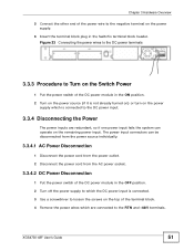
...so if one power input fails the system can operate on the remaining power input. XGS4700-48F User's Guide 51 The power input connectors can be disconnected from the power source individually. 3.3.4.1 AC Power Disconnection 1 Disconnect the power cord from the power outlet. 2 Disconnect the power... cord from the AC power socket. 3.3.4.2 DC Power Disconnection 1 Put the power switch of the power wire...
...so if one power input fails the system can operate on the remaining power input. XGS4700-48F User's Guide 51 The power input connectors can be disconnected from the power source individually. 3.3.4.1 AC Power Disconnection 1 Disconnect the power cord from the power outlet. 2 Disconnect the power... cord from the AC power socket. 3.3.4.2 DC Power Disconnection 1 Put the power switch of the power wire...
User Guide
Page 449
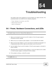
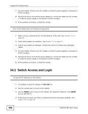
... turned on. 4 Turn the Switch off and on . The ALM LED is on (in DC models or if the DC power supply is connected in AC/DC models). 2 Make sure you are divided into the following categories. • Power, Hardware Connections, and LEDs • Switch Access and Login • ...on. 1 Make sure the Switch is connected to the Switch and plugged in AC/DC models). 6 If the problem continues, contact the vendor. Make sure the power source is connected in to solve problems you might encounter. XGS4700-48F User's Guide 449 The potential problems are using the power adaptor or cord ...
... turned on. 4 Turn the Switch off and on . The ALM LED is on (in DC models or if the DC power supply is connected in AC/DC models). 2 Make sure you are divided into the following categories. • Power, Hardware Connections, and LEDs • Switch Access and Login • ...on. 1 Make sure the Switch is connected to the Switch and plugged in AC/DC models). 6 If the problem continues, contact the vendor. Make sure the power source is connected in to solve problems you might encounter. XGS4700-48F User's Guide 449 The potential problems are using the power adaptor or cord ...
User Guide
Page 450
... to the Switch (in AC models or if the AC power supply is connected in to the Switch, the default IP address of the LED. See Section 3.1 on page 62. 450 XGS4700-48F User's Guide See Section... 4.6 on page 41. 3 Inspect your cables for the Switch. 1 The default in-band IP address is 192.168.1.1. 2 Use the console port to log in to the Switch. 3 Use the MGMT port to log in AC...the Switch off and on (in DC models or if the DC power supply is connected in AC/DC models). 2 Disconnect and re-connect the power adaptor or cord to its factory defaults. ...
... to the Switch (in AC models or if the AC power supply is connected in to the Switch, the default IP address of the LED. See Section 3.1 on page 62. 450 XGS4700-48F User's Guide See Section... 4.6 on page 41. 3 Inspect your cables for the Switch. 1 The default in-band IP address is 192.168.1.1. 2 Use the console port to log in to the Switch. 3 Use the MGMT port to log in AC...the Switch off and on (in DC models or if the DC power supply is connected in AC/DC models). 2 Disconnect and re-connect the power adaptor or cord to its factory defaults. ...
User Guide
Page 455
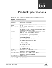
Table 169 Hardware Specifications SPECIFICATION Dimensions DESCRIPTION Standard 19" rack mountable Weight Power Specification 438 mm (W) x 425 mm (D) x 44.45 mm (H) 5.4 Kg AC: 100 - 240 VAC 50/60 Hz 1.6 A max, 143 W internal universal power supply Interfaces DC: -36 VDC ~ -72 VDC 3.7 A max, 130 W consumption. Two slots for the ...; C ~ 70º C (-13º F ~ 158º F) Ground Wire Gauge Power Wire Gauge Humidity: 10 ~ 90% (non-condensing) 18 AWG or larger 18 AWG or larger XGS4700-48F User's Guide 455
Table 169 Hardware Specifications SPECIFICATION Dimensions DESCRIPTION Standard 19" rack mountable Weight Power Specification 438 mm (W) x 425 mm (D) x 44.45 mm (H) 5.4 Kg AC: 100 - 240 VAC 50/60 Hz 1.6 A max, 143 W internal universal power supply Interfaces DC: -36 VDC ~ -72 VDC 3.7 A max, 130 W consumption. Two slots for the ...; C ~ 70º C (-13º F ~ 158º F) Ground Wire Gauge Power Wire Gauge Humidity: 10 ~ 90% (non-condensing) 18 AWG or larger 18 AWG or larger XGS4700-48F User's Guide 455