
User Guide
Page 12
... Contents 3.1.1 Mini-GBIC Slots ...41 3.1.2 Console Port ...43 3.1.3 Signal Slot ...43 3.2 Rear Panel ...46 3.2.1 Removing and Installing the Fan Module 47 3.2.2 Uplink Module ...48 3.2.3 Rear Panel Connections 48 3.2.4 Management Port ...49 3.2.5 Power Connector ...49 3.3 Power Connection ...49 3.3.1 AC Power Connections 50 3.3.2 DC Power Connections 50 3.3.3 Procedure to Turn on the Switch Power... ...71 6.1 How to Use DHCP Snooping on the Switch 71 6.2 How to Use DHCP Relay on the Switch 75 6.2.1 DHCP Relay Tutorial Introduction 75 12 XGS4700-48F User's Guide
... Contents 3.1.1 Mini-GBIC Slots ...41 3.1.2 Console Port ...43 3.1.3 Signal Slot ...43 3.2 Rear Panel ...46 3.2.1 Removing and Installing the Fan Module 47 3.2.2 Uplink Module ...48 3.2.3 Rear Panel Connections 48 3.2.4 Management Port ...49 3.2.5 Power Connector ...49 3.3 Power Connection ...49 3.3.1 AC Power Connections 50 3.3.2 DC Power Connections 50 3.3.3 Procedure to Turn on the Switch Power... ...71 6.1 How to Use DHCP Snooping on the Switch 71 6.2 How to Use DHCP Relay on the Switch 75 6.2.1 DHCP Relay Tutorial Introduction 75 12 XGS4700-48F User's Guide
User Guide
Page 22
...Setup ...424 47.3 Syslog Server Setup ...425 Chapter 48 Cluster Management...427 48.1 Clustering Management Status Overview 427 48.2 Cluster Management Status 428 48.2.1 Cluster Member Switch Management 429 48.3 Clustering Management Configuration 432 Chapter 49 MAC Table...435 ...49.1 MAC Table Overview ...435 49.2 Viewing the MAC Table ...436 Chapter 50 IP Table ...439 50.1 IP Table Overview ...439 50.2 Viewing the IP Table ...440 Chapter 51 ARP Table ...443 22 XGS4700-48F...
...Setup ...424 47.3 Syslog Server Setup ...425 Chapter 48 Cluster Management...427 48.1 Clustering Management Status Overview 427 48.2 Cluster Management Status 428 48.2.1 Cluster Member Switch Management 429 48.3 Clustering Management Configuration 432 Chapter 49 MAC Table...435 ...49.1 MAC Table Overview ...435 49.2 Viewing the MAC Table ...436 Chapter 50 IP Table ...439 50.1 IP Table Overview ...439 50.2 Viewing the IP Table ...440 Chapter 51 ARP Table ...443 22 XGS4700-48F...

User Guide
Page 27
... to -72 VDC, 3 A Max no tolerance. You can alleviate bandwidth contention and eliminate server and network bottlenecks. It can provide a XGS4700-48F User's Guide 27 By integrating router functions, the Switch performs wire-speed layer-3 routing in web configurator, managing and configuring the Switch is ...a stackabke, layer-3, Gigabit Ethernet (GbE) switch with 48 mini-GBIC slots for SFP transceivers, two power slots for two optional 2-port 10 Gigabit uplink module. See Chapter 55 on page ...
... to -72 VDC, 3 A Max no tolerance. You can alleviate bandwidth contention and eliminate server and network bottlenecks. It can provide a XGS4700-48F User's Guide 27 By integrating router functions, the Switch performs wire-speed layer-3 routing in web configurator, managing and configuring the Switch is ...a stackabke, layer-3, Gigabit Ethernet (GbE) switch with 48 mini-GBIC slots for SFP transceivers, two power slots for two optional 2-port 10 Gigabit uplink module. See Chapter 55 on page ...
User Guide
Page 41
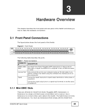
Connect the signal input pins to signal output terminals on another piece of equipment. 3.1.1 Mini-GBIC Slots These are 48 slots for fiber-optic or copper connections to a computer, a hub, an Ethernet switch or router. Use a transceiver to connect a ...) via the console port. You must use transceivers that houses a transmitter and a receiver. XGS4700-48F User's Guide 41 A transceiver is a single unit that comply with transceivers. Table 1 Panel Connections CONNECTO R 48 Mini-GBIC Slots Console Port Signal DESCRIPTION Use Small Form-Factor Pluggable (SFP) transceivers in these...
Connect the signal input pins to signal output terminals on another piece of equipment. 3.1.1 Mini-GBIC Slots These are 48 slots for fiber-optic or copper connections to a computer, a hub, an Ethernet switch or router. Use a transceiver to connect a ...) via the console port. You must use transceivers that houses a transmitter and a receiver. XGS4700-48F User's Guide 41 A transceiver is a single unit that comply with transceivers. Table 1 Panel Connections CONNECTO R 48 Mini-GBIC Slots Console Port Signal DESCRIPTION Use Small Form-Factor Pluggable (SFP) transceivers in these...
User Guide
Page 48
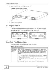
... EM-412 connection: Use 10GBase-CX4 cables to connect to these ports. See Section 3.1.1.1 on page 42 and Section 3.1.1.2 on page 42 for more information. 48 XGS4700-48F User's Guide Chapter 3 Hardware Overview 4 Slide the fan module into the fan module slot. Figure 22 The Front Panel of the EM-422 and EM...
... EM-412 connection: Use 10GBase-CX4 cables to connect to these ports. See Section 3.1.1.1 on page 42 and Section 3.1.1.2 on page 42 for more information. 48 XGS4700-48F User's Guide Chapter 3 Hardware Overview 4 Slide the fan module into the fan module slot. Figure 22 The Front Panel of the EM-422 and EM...
User Guide
Page 53
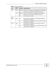
... is disconnected. Chapter 3 Hardware Overview Table 3 LEDs (continued) LED COLO R STATUS 1-48 Green Blinking On Amber Blinking On Off 10G 49-50 Blue On Off 51-52 Blue On Off DESCRIPTION The port is receiving or transmitting data 100 Mbps. XGS4700-48F User's Guide 53 This link is connected to other switches through...
... is disconnected. Chapter 3 Hardware Overview Table 3 LEDs (continued) LED COLO R STATUS 1-48 Green Blinking On Amber Blinking On Off 10G 49-50 Blue On Off 51-52 Blue On Off DESCRIPTION The port is receiving or transmitting data 100 Mbps. XGS4700-48F User's Guide 53 This link is connected to other switches through...
User Guide
Page 128
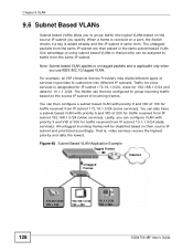
....1.1.0/24. The untagged packets from IP subnet 192.168.1.0/24 (video services). Figure 48 Subnet Based VLAN Application Example Tagged Frames Internet Untagged Frames 172.16.1.0/24 VID = 100 192.168.1.0/24 VID = 200 10.1.1.0/24 VID = 300 128 XGS4700-48F User's Guide For example, an ISP (Internet Service Provider) may divide different...
....1.1.0/24. The untagged packets from IP subnet 192.168.1.0/24 (video services). Figure 48 Subnet Based VLAN Application Example Tagged Frames Internet Untagged Frames 172.16.1.0/24 VID = 100 192.168.1.0/24 VID = 200 10.1.1.0/24 VID = 300 128 XGS4700-48F User's Guide For example, an ISP (Internet Service Provider) may divide different...
User Guide
Page 202
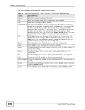
Table 48 Advanced Application > Port Security > VLAN MAC Address Limit LABEL DESCRIPTION Active Select this option to activate this field to the Switch's run-time memory. "0" means ... is the VLAN ID number to save your previous configuration. Chapter 19 Port Security The following table describes the labels in the Delete column. 202 XGS4700-48F User's Guide Add Click Add to save your changes to remove in a VLAN. VID This is it is applied. Click an index number to the...
Table 48 Advanced Application > Port Security > VLAN MAC Address Limit LABEL DESCRIPTION Active Select this option to activate this field to the Switch's run-time memory. "0" means ... is the VLAN ID number to save your previous configuration. Chapter 19 Port Security The following table describes the labels in the Delete column. 202 XGS4700-48F User's Guide Add Click Add to save your changes to remove in a VLAN. VID This is it is applied. Click an index number to the...
User Guide
Page 222
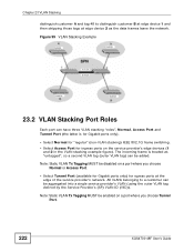
...or Access Port. • Select Tunnel Port (available for Gigabit ports only) for ingress ports on a port where you choose Tunnel Port. 222 XGS4700-48F User's Guide Note: Static VLAN Tx Tagging MUST be added. The incoming frame is for Gigabit ports only). • Select Normal for "regular"... Select Access Port for egress ports at edge device 2 as the data frames leave the network. Chapter 23 VLAN Stacking distinguish customer A and tag 48 to a customer can be aggregated into a single service provider's VLAN (using the outer VLAN tag defined by the Service Provider's (SP) VLAN ID...
...or Access Port. • Select Tunnel Port (available for Gigabit ports only) for ingress ports on a port where you choose Tunnel Port. 222 XGS4700-48F User's Guide Note: Static VLAN Tx Tagging MUST be added. The incoming frame is for Gigabit ports only). • Select Normal for "regular"... Select Access Port for egress ports at edge device 2 as the data frames leave the network. Chapter 23 VLAN Stacking distinguish customer A and tag 48 to a customer can be aggregated into a single service provider's VLAN (using the outer VLAN tag defined by the Service Provider's (SP) VLAN ID...
User Guide
Page 357
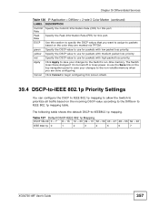
... marked via TRTCM. Table 127 Default DSCP-IEEE 802.1p Mapping DSCP VALUE 0 - 7 8 - 15 16 - 23 24 - 31 32 - 39 40 - 47 48 - 55 56 - 63 IEEE 802.1p 0 1 2 3 4 5 6 7 XGS4700-48F User's Guide 357 Cancel Click Cancel to begin configuring this section to packets based on the incoming DSCP value according to the...
... marked via TRTCM. Table 127 Default DSCP-IEEE 802.1p Mapping DSCP VALUE 0 - 7 8 - 15 16 - 23 24 - 31 32 - 39 40 - 47 48 - 55 56 - 63 IEEE 802.1p 0 1 2 3 4 5 6 7 XGS4700-48F User's Guide 357 Cancel Click Cancel to begin configuring this section to packets based on the incoming DSCP value according to the...
User Guide
Page 379
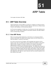
In an Ethernet LAN, MAC addresses are 48 bits long. The ARP Table maintains an association between each MAC address and its own MAC and IP address in the sender address fields, and ... being sought or the router that replied. 42.1.2 ARP Learning Mode The Switch supports three ARP learning modes: ARP-Reply, Gratuitous-ARP, and ARP-Request. XGS4700-48F User's Guide 379 ARP updates the ARP Table for future reference and then sends the packet to the MAC address that knows the way) replaces...
In an Ethernet LAN, MAC addresses are 48 bits long. The ARP Table maintains an association between each MAC address and its own MAC and IP address in the sender address fields, and ... being sought or the router that replied. 42.1.2 ARP Learning Mode The Switch supports three ARP learning modes: ARP-Reply, Gratuitous-ARP, and ARP-Request. XGS4700-48F User's Guide 379 ARP updates the ARP Table for future reference and then sends the packet to the MAC address that knows the way) replaces...
User Guide
Page 427
.... The switches must be able to manage switches through one another. XGS4700-48F User's Guide 427 Cluster Manager The cluster manager is the Switch through which you to communicate with ZyXEL cluster management implementation. CHAPTER 48 Cluster Management This chapter introduces cluster management. 48.1 Clustering Management Status Overview Cluster Management allows you manage the cluster...
.... The switches must be able to manage switches through one another. XGS4700-48F User's Guide 427 Cluster Manager The cluster manager is the Switch through which you to communicate with ZyXEL cluster management implementation. CHAPTER 48 Cluster Management This chapter introduces cluster management. 48.1 Clustering Management Status Overview Cluster Management allows you manage the cluster...
User Guide
Page 428
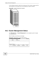
Figure 240 Clustering Application Example 48.2 Cluster Management Status Click Management > Cluster Management in the basement is the cluster manager and the other switches on the upper floors of the building are cluster members. Figure 241 Management > Cluster Management 428 XGS4700-48F User's Guide Note: A cluster can only have one manager. Chapter 48 Cluster Management In the following example, switch A in the navigation panel to display the following screen.
Figure 240 Clustering Application Example 48.2 Cluster Management Status Click Management > Cluster Management in the basement is the cluster manager and the other switches on the upper floors of the building are cluster members. Figure 241 Management > Cluster Management 428 XGS4700-48F User's Guide Note: A cluster can only have one manager. Chapter 48 Cluster Management In the following example, switch A in the navigation panel to display the following screen.
User Guide
Page 429
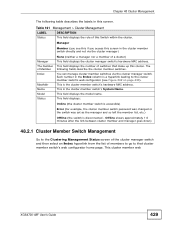
... this if you access this cluster. This is disconnected - Offline shows approximately 1.5 minutes after the link between cluster member and manager goes down) 48.2.1 Cluster Member Switch Management Go to the Clustering Management Status screen of the cluster manager switch and then select an Index hyperlink from the list.... The following table describes the labels in the cluster member switch directly and not via the cluster manager switch. This cluster member web XGS4700-48F User's Guide 429 Chapter 48 Cluster Management The following fields describe the cluster member switches.
... this if you access this cluster. This is disconnected - Offline shows approximately 1.5 minutes after the link between cluster member and manager goes down) 48.2.1 Cluster Member Switch Management Go to the Clustering Management Status screen of the cluster manager switch and then select an Index hyperlink from the list.... The following table describes the labels in the cluster member switch directly and not via the cluster manager switch. This cluster member web XGS4700-48F User's Guide 429 Chapter 48 Cluster Management The following fields describe the cluster member switches.
User Guide
Page 430
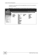
Figure 242 Cluster Management: Cluster Member Web Configurator Screen EXAMPLE EXAMPLE 430 XGS4700-48F User's Guide Chapter 48 Cluster Management configurator home page and the home page that you'd see if you accessed it directly are different.
Figure 242 Cluster Management: Cluster Member Web Configurator Screen EXAMPLE EXAMPLE 430 XGS4700-48F User's Guide Chapter 48 Cluster Management configurator home page and the home page that you'd see if you accessed it directly are different.
User Guide
Page 431
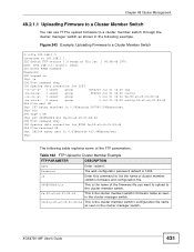
...file name as seen in 0.00Seconds 297000.00Kbytes/sec. config-00-a0-c5-01-23-46 This is the name of the FTP parameters. XGS4700-48F User's Guide 431 ftp> bin 200 Type I OK ftp> put 400BVG0b6.bin fw-00-a0-c5-01-23-46 200 Port command okay... following example. The web configurator password default is the cluster member switch's firmware name as seen in 0.63Seconds 415.44Kbytes/sec. Chapter 48 Cluster Management 48.2.1.1 Uploading Firmware to a Cluster Member Switch You can use FTP to upload firmware to Cluster Member Example FTP PARAMETER User Password ls DESCRIPTION...
...file name as seen in 0.00Seconds 297000.00Kbytes/sec. config-00-a0-c5-01-23-46 This is the name of the FTP parameters. XGS4700-48F User's Guide 431 ftp> bin 200 Type I OK ftp> put 400BVG0b6.bin fw-00-a0-c5-01-23-46 200 Port command okay... following example. The web configurator password default is the cluster member switch's firmware name as seen in 0.63Seconds 415.44Kbytes/sec. Chapter 48 Cluster Management 48.2.1.1 Uploading Firmware to a Cluster Member Switch You can use FTP to upload firmware to Cluster Member Example FTP PARAMETER User Password ls DESCRIPTION...

User Guide
Page 432
...Clustering Manager DESCRIPTION Active Select Active to be cluster managers will not be directly connected and in the Clustering Candidates list. based VLAN. 432 XGS4700-48F User's Guide Name Type a name to 32 printable characters (spaces are allowed). This field is ignored if the Clustering Manager is set ...that was previously a cluster member is displayed as Error in the Cluster Management Status screen appears in the Clustering Candidates list. Chapter 48 Cluster Management 48.3 Clustering Management Configuration Use this screen to display the next screen.
...Clustering Manager DESCRIPTION Active Select Active to be cluster managers will not be directly connected and in the Clustering Candidates list. based VLAN. 432 XGS4700-48F User's Guide Name Type a name to 32 printable characters (spaces are allowed). This field is ignored if the Clustering Manager is set ...that was previously a cluster member is displayed as Error in the Cluster Management Status screen appears in the Clustering Candidates list. Chapter 48 Cluster Management 48.3 Clustering Management Configuration Use this screen to display the next screen.
User Guide
Page 433
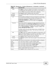
... to perform auto-discovery again to select them. The next summary table shows the information for the clustering members configured. XGS4700-48F User's Guide 433 The following fields relate to the switches that switch administrator changes the web configurator password afterwards, then .... If multiple devices have the same password then hold [SHIFT] and click those switches to list potential cluster members. Chapter 48 Cluster Management Table 163 Management > Clustering Management > Configuration (continued) LABEL Apply Cancel Clustering Candidate List Password DESCRIPTION Click Apply...
... to perform auto-discovery again to select them. The next summary table shows the information for the clustering members configured. XGS4700-48F User's Guide 433 The following fields relate to the switches that switch administrator changes the web configurator password afterwards, then .... If multiple devices have the same password then hold [SHIFT] and click those switches to list potential cluster members. Chapter 48 Cluster Management Table 163 Management > Clustering Management > Configuration (continued) LABEL Apply Cancel Clustering Candidate List Password DESCRIPTION Click Apply...
User Guide
Page 443
...) replaces the broadcast address with the target's MAC address, swaps the sender and target pairs, and unicasts the answer directly back to the requesting machine. XGS4700-48F User's Guide 443 An IP (version 4) address is the Ethernet broadcast address). In an Ethernet LAN, MAC addresses are...
...) replaces the broadcast address with the target's MAC address, swaps the sender and target pairs, and unicasts the answer directly back to the requesting machine. XGS4700-48F User's Guide 443 An IP (version 4) address is the Ethernet broadcast address). In an Ethernet LAN, MAC addresses are...
User Guide
Page 455
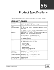
...-232 console port Main switch: PWR1, PWR2, SYS, ALM The 100Base-T management port: MGMT Green: 10 Mbps Amber: 100 Mbps Per mini-GBIC port: 1~48 Operating Environment Storage Environment steady: link state blinking: transmitting/receiving Per stacking port: 49~52 Temperature: 0º C ~ 45º C (32º F... ~ 90% (non-condensing) 18 AWG or larger 18 AWG or larger XGS4700-48F User's Guide 455 There is no tolerance for optional 10G uplink module sets. Two slots for the DC input voltage. 48 mini-GBIC slots, compatible with Small Form-Factor Pluggable (SFP) Multi Source ...
...-232 console port Main switch: PWR1, PWR2, SYS, ALM The 100Base-T management port: MGMT Green: 10 Mbps Amber: 100 Mbps Per mini-GBIC port: 1~48 Operating Environment Storage Environment steady: link state blinking: transmitting/receiving Per stacking port: 49~52 Temperature: 0º C ~ 45º C (32º F... ~ 90% (non-condensing) 18 AWG or larger 18 AWG or larger XGS4700-48F User's Guide 455 There is no tolerance for optional 10G uplink module sets. Two slots for the DC input voltage. 48 mini-GBIC slots, compatible with Small Form-Factor Pluggable (SFP) Multi Source ...