

User Guide
Page 3
... 2 Hardware Description and Connection 9 2.1 Rear Panel ...9 2.1.1 Rear Panel Power Connection 9 2.2 Front Panel ...9 2.2.1 RJ-45 Auto-negotiating Ports 10 2.2.2 IEEE 802.3az EEE ...10 2.2.3 SFP Slots (GS1100-24 Only 10 2.2.4 Front Panel Connections ...12 2.2.5 Front Panel LEDs ...12 2.3 Hardware Installation ...14 2.3.1 Wall Mounting ...14 2.3.2 Rack Mounting ...15 2.3.3 Mounting the Switch on a Rack 16...
... 2 Hardware Description and Connection 9 2.1 Rear Panel ...9 2.1.1 Rear Panel Power Connection 9 2.2 Front Panel ...9 2.2.1 RJ-45 Auto-negotiating Ports 10 2.2.2 IEEE 802.3az EEE ...10 2.2.3 SFP Slots (GS1100-24 Only 10 2.2.4 Front Panel Connections ...12 2.2.5 Front Panel LEDs ...12 2.3 Hardware Installation ...14 2.3.1 Wall Mounting ...14 2.3.2 Rack Mounting ...15 2.3.3 Mounting the Switch on a Rack 16...

User Guide
Page 5
...in compliance with IEEE 802.3az Energy Efficient Ethernet (EEE). Table 1 GS1100 Series Comparison Table PORT/SWITCH DETAILS GS1100-8HP GS1100-16 8 10/100/1000Base-T Ethernet ports (including 4 PoE ports) 16 10/100/1000Base-T Ethernet ports 24 10/100/1000Base-T Ethernet ports 2 100/1000Base-X SFP slots One ...physical IEEE 802.3az ON/OFF button One power ON/OFF switch GS1100-24 GS1100-24E The GS1100-8HP has four GbE PoE ports that automatically assigns priority to build highperformance switched workgroup networks. It can be used to ...
...in compliance with IEEE 802.3az Energy Efficient Ethernet (EEE). Table 1 GS1100 Series Comparison Table PORT/SWITCH DETAILS GS1100-8HP GS1100-16 8 10/100/1000Base-T Ethernet ports (including 4 PoE ports) 16 10/100/1000Base-T Ethernet ports 24 10/100/1000Base-T Ethernet ports 2 100/1000Base-X SFP slots One ...physical IEEE 802.3az ON/OFF button One power ON/OFF switch GS1100-24 GS1100-24E The GS1100-8HP has four GbE PoE ports that automatically assigns priority to build highperformance switched workgroup networks. It can be used to ...

User Guide
Page 6
...Supports automatic address learning. • Supports IEEE 802.3az EEE • Supports IEEE 802.3af and IEEE 802.3at PoE standards (only GS1100-8HP) • Full wire speed forwarding rate. • Supports 802.1p CoS. • Embedded 8K MAC address table providing 8000 MAC ...1.3 Applications This section provides two network topology examples in which the Switch is used. 6 GS1100 Series User's Guide Chapter 1 Getting to Know Your Switch Figure 1 Front Panel GS1100-8HP GS1100-16 GS1100-24 GS1100-24E 1.2 Features The following are the essential features of the Switch. • Conforms to...
...Supports automatic address learning. • Supports IEEE 802.3az EEE • Supports IEEE 802.3af and IEEE 802.3at PoE standards (only GS1100-8HP) • Full wire speed forwarding rate. • Supports 802.1p CoS. • Embedded 8K MAC address table providing 8000 MAC ...1.3 Applications This section provides two network topology examples in which the Switch is used. 6 GS1100 Series User's Guide Chapter 1 Getting to Know Your Switch Figure 1 Front Panel GS1100-8HP GS1100-16 GS1100-24 GS1100-24E 1.2 Features The following are the essential features of the Switch. • Conforms to...

User Guide
Page 9
... 9 Figure 5 Rear Panel GS1100-8HP GS1100-16 GS1100-24 GS1100-24E 2.1.1 Rear Panel Power Connection Connect one end of the supplied power cord or power adaptor to the power receptacle on the back of the Switch and the other end to the power supply requirements on the panel. For the GS1100-8HP, GS1100-16 and GS1100-24E, use the POWER...
... 9 Figure 5 Rear Panel GS1100-8HP GS1100-16 GS1100-24 GS1100-24E 2.1.1 Rear Panel Power Connection Connect one end of the supplied power cord or power adaptor to the power receptacle on the back of the Switch and the other end to the power supply requirements on the panel. For the GS1100-8HP, GS1100-16 and GS1100-24E, use the POWER...

User Guide
Page 10
...speed (10/100/1000 Mpbs) and duplex mode (full duplex or half duplex) of PCB board facing down. 10 GS1100 Series User's Guide EEE is data to help reduce power consumption. See the SFF committee's INF-8074i specification Rev ... saving mode and switch off part of fiber-optic or even copper cable connectors. Disable it . 2.2.3 SFP Slots (GS1100-24 Only) These are auto-negotiating and auto-crossover. To avoid possible eye injury, do not look into the slot with... the network performance to be EEE compliant. Chapter 2 Hardware Description and Connection The GS1100-24 has two SFP slots.
...speed (10/100/1000 Mpbs) and duplex mode (full duplex or half duplex) of PCB board facing down. 10 GS1100 Series User's Guide EEE is data to help reduce power consumption. See the SFF committee's INF-8074i specification Rev ... saving mode and switch off part of fiber-optic or even copper cable connectors. Disable it . 2.2.3 SFP Slots (GS1100-24 Only) These are auto-negotiating and auto-crossover. To avoid possible eye injury, do not look into the slot with... the network performance to be EEE compliant. Chapter 2 Hardware Description and Connection The GS1100-24 has two SFP slots.

User Guide
Page 13
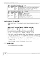
...Off Power supplied to the PoE port. Blinking The port is below the power budget limit. Table 3 The Front Panel LED Descriptions: GS1100-8HP LED COLOR STATUS DESCRIPTION PWR Green On The Switch is on the Switch. Off The Switch is connected to the PoE port. 1G ...Green On The port is not receiving power. Figure 11 Front Panel LEDs GS1100-8HP GS1100-16 GS1100-24 GS1100-24E Chapter 2 Hardware Description and Connection The following table describes the LEDs. Off Power is not supplied to an Ethernet network at ...
...Off Power supplied to the PoE port. Blinking The port is below the power budget limit. Table 3 The Front Panel LED Descriptions: GS1100-8HP LED COLOR STATUS DESCRIPTION PWR Green On The Switch is on the Switch. Off The Switch is connected to the PoE port. 1G ...Green On The port is not receiving power. Figure 11 Front Panel LEDs GS1100-8HP GS1100-16 GS1100-24 GS1100-24E Chapter 2 Hardware Description and Connection The following table describes the LEDs. Off Power is not supplied to an Ethernet network at ...
User Guide
Page 14
... hardware installation methods of your Switch to an Ethernet network. For GS1100-8HP, GS1100-16 and GS110-24E, you can place the Switch directly on top of each GS1100 model: Table 5 GS1100 Series Installation Comparison Table MODEL FEATURE Desktop Device Wall-mountable Rack-mountable GS1100-8HP GS1100-16 GS1100-24 GS1100-24E Note: Ask an authorized technician to attach the Switch...
... hardware installation methods of your Switch to an Ethernet network. For GS1100-8HP, GS1100-16 and GS110-24E, you can place the Switch directly on top of each GS1100 model: Table 5 GS1100 Series Installation Comparison Table MODEL FEATURE Desktop Device Wall-mountable Rack-mountable GS1100-8HP GS1100-16 GS1100-24 GS1100-24E Note: Ask an authorized technician to attach the Switch...
User Guide
Page 15
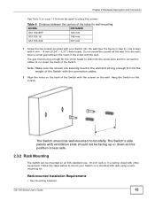
...the Switch. Hang the Switch on the wall. Chapter 2 Hardware Description and Connection See Table 6 on page 15 for wall mounting MODEL GS1100-8HP GS1100-16 DISTANCE 120 mm 148 mm GS1100-24E 207 mm 1 Screw the two screws provided with your Switch on a standard EIA rack using a rackmounting kit. Do not screw the...cables to the wall; Table 6 Distance between the head of the Switch with the screws on the screws. The Switch's side panels with 6 mm ~ 8 mm (0.24" ~ 0.31") wide heads. The gap must be big enough for the screw heads to slide into the wall (see the figure in to run down...
...the Switch. Hang the Switch on the wall. Chapter 2 Hardware Description and Connection See Table 6 on page 15 for wall mounting MODEL GS1100-8HP GS1100-16 DISTANCE 120 mm 148 mm GS1100-24E 207 mm 1 Screw the two screws provided with your Switch on a standard EIA rack using a rackmounting kit. Do not screw the...cables to the wall; Table 6 Distance between the head of the Switch with the screws on the screws. The Switch's side panels with 6 mm ~ 8 mm (0.24" ~ 0.31") wide heads. The gap must be big enough for the screw heads to slide into the wall (see the figure in to run down...

User Guide
Page 16
... the second mounting bracket on the side of the Switch. 4 You may damage the unit. Figure 12 Attaching the Mounting Brackets (GS1100-16 and GS1100-24E) Figure 13 Attaching the Mounting Brackets (GS1100-24) 2 Using a #2 Philips screwdriver, install the M3 flat head screws through the mounting bracket holes into the Switch. 3 Repeat steps 1 and...
... the second mounting bracket on the side of the Switch. 4 You may damage the unit. Figure 12 Attaching the Mounting Brackets (GS1100-16 and GS1100-24E) Figure 13 Attaching the Mounting Brackets (GS1100-24) 2 Using a #2 Philips screwdriver, install the M3 flat head screws through the mounting bracket holes into the Switch. 3 Repeat steps 1 and...

User Guide
Page 17
GS1100 Series User's Guide 17 Chapter 2 Hardware Description and Connection Figure 14 Mounting the Switch on a Rack (GS1100-16 and GS1100-24E) Figure 15 Mounting the Switch on a Rack (GS1100-24) 2 Using a #2 Philips screwdriver, install the M5 flat head screws through the mounting bracket holes into the rack. 3 Repeat steps 1 and 2 to attach the second mounting bracket on the other side of the rack.
GS1100 Series User's Guide 17 Chapter 2 Hardware Description and Connection Figure 14 Mounting the Switch on a Rack (GS1100-16 and GS1100-24E) Figure 15 Mounting the Switch on a Rack (GS1100-24) 2 Using a #2 Philips screwdriver, install the M5 flat head screws through the mounting bracket holes into the rack. 3 Repeat steps 1 and 2 to attach the second mounting bracket on the other side of the rack.

User Guide
Page 24
Index P PD 8 PoE 8 power supplying 8 Power over Ethernet 8 power saving 10 powered device 8 product registration 22 R rack mounting 15 Rear Panel 9 Rear Panel Power Connection 9 registration product 22 S safety warnings 22 Small Form-factor Pluggable (SFP) 10 Standalone Workgroup 7 T transceiver MultiSource Agreement (MSA) 10 transceivers 10 installation 10 removal 11 Troubleshooting Improper Network Cabling and Topology 20 W wall mounting 14 warranty 21 note 22 24 GS1100 Series User's Guide
Index P PD 8 PoE 8 power supplying 8 Power over Ethernet 8 power saving 10 powered device 8 product registration 22 R rack mounting 15 Rear Panel 9 Rear Panel Power Connection 9 registration product 22 S safety warnings 22 Small Form-factor Pluggable (SFP) 10 Standalone Workgroup 7 T transceiver MultiSource Agreement (MSA) 10 transceivers 10 installation 10 removal 11 Troubleshooting Improper Network Cabling and Topology 20 W wall mounting 14 warranty 21 note 22 24 GS1100 Series User's Guide