

User Guide
Page 3
... 2 Hardware Description and Connection 9 2.1 Rear Panel ...9 2.1.1 Rear Panel Power Connection 9 2.2 Front Panel ...9 2.2.1 RJ-45 Auto-negotiating Ports 10 2.2.2 IEEE 802.3az EEE ...10 2.2.3 SFP Slots (GS1100-24 Only 10 2.2.4 Front Panel Connections ...12 2.2.5 Front Panel LEDs ...12 2.3 Hardware Installation ...14 2.3.1 Wall Mounting ...14 2.3.2 Rack Mounting ...15 2.3.3 Mounting the Switch on a Rack 16 Chapter 3 Troubleshooting...19 3.1 Improper Network Cabling and Topology 20 Appendix A Legal Information...21 Index ...23 GS1100 Series User's Guide 3
... 2 Hardware Description and Connection 9 2.1 Rear Panel ...9 2.1.1 Rear Panel Power Connection 9 2.2 Front Panel ...9 2.2.1 RJ-45 Auto-negotiating Ports 10 2.2.2 IEEE 802.3az EEE ...10 2.2.3 SFP Slots (GS1100-24 Only 10 2.2.4 Front Panel Connections ...12 2.2.5 Front Panel LEDs ...12 2.3 Hardware Installation ...14 2.3.1 Wall Mounting ...14 2.3.2 Rack Mounting ...15 2.3.3 Mounting the Switch on a Rack 16 Chapter 3 Troubleshooting...19 3.1 Improper Network Cabling and Topology 20 Appendix A Legal Information...21 Index ...23 GS1100 Series User's Guide 3

User Guide
Page 5
... The GS1100-8HP has four GbE PoE ports that can operate in low power idle mode in algorithm that offers low latency for small businesses. It can be used to the connected PoE powered devices. The Switch is fanless and designed for workgroups, departments or backbone computing environments for high-speed networking. GS1100 Series User's Guide 5 CHAPTER 1 Getting to Know Your Switch 1.1 Introduction This chapter describes the key...
... The GS1100-8HP has four GbE PoE ports that can operate in low power idle mode in algorithm that offers low latency for small businesses. It can be used to the connected PoE powered devices. The Switch is fanless and designed for workgroups, departments or backbone computing environments for high-speed networking. GS1100 Series User's Guide 5 CHAPTER 1 Getting to Know Your Switch 1.1 Introduction This chapter describes the key...

User Guide
Page 6
....3af and IEEE 802.3at PoE standards (only GS1100-8HP) • Full wire speed forwarding rate. • Supports 802.1p CoS. • Embedded 8K MAC address table providing 8000 MAC addresses entries. 1.3 Applications This section provides two network topology examples in which the Switch is used. 6 GS1100 Series User's Guide Chapter 1 Getting to Know Your Switch Figure 1 Front Panel GS1100-8HP GS1100-16 GS1100-24 GS1100-24E 1.2 Features The following are the essential...
....3af and IEEE 802.3at PoE standards (only GS1100-8HP) • Full wire speed forwarding rate. • Supports 802.1p CoS. • Embedded 8K MAC address table providing 8000 MAC addresses entries. 1.3 Applications This section provides two network topology examples in which the Switch is used. 6 GS1100 Series User's Guide Chapter 1 Getting to Know Your Switch Figure 1 Front Panel GS1100-8HP GS1100-16 GS1100-24 GS1100-24E 1.2 Features The following are the essential...
User Guide
Page 7
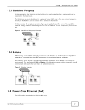
... networks where rapid growth can be used standalone for GS1100-8HP only. To expand the network, simply add more networking devices such as switches, routers, computers, print servers etc. Figure 2 Standalone Workgroup Example 1.3.2 Bridging With its large address table and high performance, the Switch is available for a group of the Switch in the near future. GS1100 Series User's Guide 7 The following figure depicts a typical segment bridge application of heavy traffic users. Figure 3 Bridging Example 1.4 Power Over Ethernet...
... networks where rapid growth can be used standalone for GS1100-8HP only. To expand the network, simply add more networking devices such as switches, routers, computers, print servers etc. Figure 2 Standalone Workgroup Example 1.3.2 Bridging With its large address table and high performance, the Switch is available for a group of the Switch in the near future. GS1100 Series User's Guide 7 The following figure depicts a typical segment bridge application of heavy traffic users. Figure 3 Bridging Example 1.4 Power Over Ethernet...
User Guide
Page 8
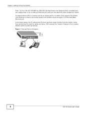
Figure 4 Powered Device Examples 8 GS1100 Series User's Guide Aside from the Switch. In the figure below, the IP camera and IP phone get their power directly from minimizing the need for cables and wires, PoE removes the hassle of up to 30W per Ethernet port and up devices. Chapter 1 Getting to Know Your Switch Ports 1 to 4 on the GS1100-8HP are IEEE 802.3at High Power over Ethernet) so that supports PoE (Power over Ethernet (PoE) compliant and can...
Figure 4 Powered Device Examples 8 GS1100 Series User's Guide Aside from the Switch. In the figure below, the IP camera and IP phone get their power directly from minimizing the need for cables and wires, PoE removes the hassle of up to 30W per Ethernet port and up devices. Chapter 1 Getting to Know Your Switch Ports 1 to 4 on the GS1100-8HP are IEEE 802.3at High Power over Ethernet) so that supports PoE (Power over Ethernet (PoE) compliant and can...

User Guide
Page 9
CHAPTER 2 Hardware Description and Connection 2.1 Rear Panel The power receptacle is located on the panel. GS1100 Series User's Guide 9 Refer to the power supply requirements on the rear panel of the Switch. Figure 5 Rear Panel GS1100-8HP GS1100-16 GS1100-24 GS1100-24E 2.1.1 Rear Panel Power Connection Connect one end of the supplied power cord or power adaptor to the power receptacle on or off. 2.2 Front Panel The front panel of the Switch and...
CHAPTER 2 Hardware Description and Connection 2.1 Rear Panel The power receptacle is located on the panel. GS1100 Series User's Guide 9 Refer to the power supply requirements on the rear panel of the Switch. Figure 5 Rear Panel GS1100-8HP GS1100-16 GS1100-24 GS1100-24E 2.1.1 Rear Panel Power Connection Connect one end of the supplied power cord or power adaptor to the power receptacle on or off. 2.2 Front Panel The front panel of the Switch and...

User Guide
Page 10
.... An EEE-enabled device initiates Low Power Idle (LPI) signals to install a SFP module. 1 Insert the transceiver into power saving mode and switch off part of fiber-optic or even copper cable connectors. Chapter 2 Hardware Description and Connection The GS1100-24 has two SFP slots. To avoid possible eye injury, do not look into an operating fiber-optic module's connectors. • Type: SFP connection interface • Connection speed: 100...
.... An EEE-enabled device initiates Low Power Idle (LPI) signals to install a SFP module. 1 Insert the transceiver into power saving mode and switch off part of fiber-optic or even copper cable connectors. Chapter 2 Hardware Description and Connection The GS1100-24 has two SFP slots. To avoid possible eye injury, do not look into an operating fiber-optic module's connectors. • Type: SFP connection interface • Connection speed: 100...

User Guide
Page 11
... Switch automatically detects the installed transceiver. Chapter 2 Hardware Description and Connection 2 Press the transceiver firmly until it is functioning properly. 4 Close the transceiver's latch (latch styles vary). 5 Connect the fiber optic cables to the transceiver. Figure 8 Removing the Fiber Optic Cables Figure 9 Opening the Transceiver's Latch Example GS1100 Series User's Guide 11 Figure 6 Transceiver Installation Example Figure 7 Connecting the Fiber Optic Cables 2.2.3.2 Transceiver Removal Use the following steps to remove a SFP module. 1 Remove the...
... Switch automatically detects the installed transceiver. Chapter 2 Hardware Description and Connection 2 Press the transceiver firmly until it is functioning properly. 4 Close the transceiver's latch (latch styles vary). 5 Connect the fiber optic cables to the transceiver. Figure 8 Removing the Fiber Optic Cables Figure 9 Opening the Transceiver's Latch Example GS1100 Series User's Guide 11 Figure 6 Transceiver Installation Example Figure 7 Connecting the Fiber Optic Cables 2.2.3.2 Transceiver Removal Use the following steps to remove a SFP module. 1 Remove the...

User Guide
Page 12
... ports. 2.2.5 Front Panel LEDs The LED Indicators give real-time information about the status of the LEDs. 12 GS1100 Series User's Guide The following table describes the types of network cable used for RJ-45 ports. The following table provides descriptions of the Switch. Chapter 2 Hardware Description and Connection Figure 10 Transceiver Removal Example 2.2.4 Front Panel Connections You can use unshielded twisted pair (UTP) or shielded twisted-pair (STP) Ethernet cables for the different connection speeds...
... ports. 2.2.5 Front Panel LEDs The LED Indicators give real-time information about the status of the LEDs. 12 GS1100 Series User's Guide The following table describes the types of network cable used for RJ-45 ports. The following table provides descriptions of the Switch. Chapter 2 Hardware Description and Connection Figure 10 Transceiver Removal Example 2.2.4 Front Panel Connections You can use unshielded twisted pair (UTP) or shielded twisted-pair (STP) Ethernet cables for the different connection speeds...

User Guide
Page 13
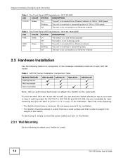
... speed. Off The port is on the Switch. Table 3 The Front Panel LED Descriptions: GS1100-8HP LED COLOR STATUS DESCRIPTION PWR Green On The Switch is not connected to the PoE port(s) reachs the power budget limit or exceeds the total PoE power budget on and receiving power. GS1100 Series User's Guide 13 PoE MAX Red On Power supplied to an Ethernet network. Off Power is not supplied to the PoE port. 1G Green On The port...
... speed. Off The port is on the Switch. Table 3 The Front Panel LED Descriptions: GS1100-8HP LED COLOR STATUS DESCRIPTION PWR Green On The Switch is not connected to the PoE port(s) reachs the power budget limit or exceeds the total PoE power budget on and receiving power. GS1100 Series User's Guide 13 PoE MAX Red On Power supplied to an Ethernet network. Off Power is not supplied to the PoE port. 1G Green On The port...
User Guide
Page 14
... GS1100 Series User's Guide Chapter 2 Hardware Description and Connection Table 3 The Front Panel LED Descriptions: GS1100-8HP LED COLOR STATUS DESCRIPTION 10/100 Amber On The port is connected to an Ethernet network at 10M or 100M speed. Off The port is not connected to an Ethernet network. 2.3 Hardware Installation See the following to attach your desk or have a minimum 25 mm space around it , simply connect the power cables and turn on the Switch. 2.3.1 Wall Mounting Do...
... GS1100 Series User's Guide Chapter 2 Hardware Description and Connection Table 3 The Front Panel LED Descriptions: GS1100-8HP LED COLOR STATUS DESCRIPTION 10/100 Amber On The port is connected to an Ethernet network at 10M or 100M speed. Off The port is not connected to an Ethernet network. 2.3 Hardware Installation See the following to attach your desk or have a minimum 25 mm space around it , simply connect the power cables and turn on the Switch. 2.3.1 Wall Mounting Do...
User Guide
Page 15
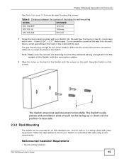
GS1100 Series User's Guide 15 Hang the Switch on the screws. Do not screw the screws all the way in step 2). leave a small gap between the centers of the screw and the wall. Use ...mounting MODEL GS1100-8HP GS1100-16 DISTANCE 120 mm 148 mm GS1100-24E 207 mm 1 Screw the two screws provided with your Switch on a standard EIA rack using a rackmounting kit. Rack-mounted Installation Requirements • Two mounting brackets. The Switch should not be wall-mounted horizontally. Follow the steps below to mount your Switch into the screw slots and the connection cables...
GS1100 Series User's Guide 15 Hang the Switch on the screws. Do not screw the screws all the way in step 2). leave a small gap between the centers of the screw and the wall. Use ...mounting MODEL GS1100-8HP GS1100-16 DISTANCE 120 mm 148 mm GS1100-24E 207 mm 1 Screw the two screws provided with your Switch on a standard EIA rack using a rackmounting kit. Rack-mounted Installation Requirements • Two mounting brackets. The Switch should not be wall-mounted horizontally. Follow the steps below to mount your Switch into the screw slots and the connection cables...

User Guide
Page 16
... to the Switch 1 Position a mounting bracket on one side of the rack, lining up the four screw holes on the bracket with the screw holes on the other side of the Switch does not make the rack unstable or top-heavy. Precautions • Make sure the rack will safely support the combined weight of the rack. 16 GS1100 Series User's Guide
... to the Switch 1 Position a mounting bracket on one side of the rack, lining up the four screw holes on the bracket with the screw holes on the other side of the Switch does not make the rack unstable or top-heavy. Precautions • Make sure the rack will safely support the combined weight of the rack. 16 GS1100 Series User's Guide

User Guide
Page 17
Chapter 2 Hardware Description and Connection Figure 14 Mounting the Switch on a Rack (GS1100-16 and GS1100-24E) Figure 15 Mounting the Switch on a Rack (GS1100-24) 2 Using a #2 Philips screwdriver, install the M5 flat head screws through the mounting bracket holes into the rack. 3 Repeat steps 1 and 2 to attach the second mounting bracket on the other side of the rack. GS1100 Series User's Guide 17
Chapter 2 Hardware Description and Connection Figure 14 Mounting the Switch on a Rack (GS1100-16 and GS1100-24E) Figure 15 Mounting the Switch on a Rack (GS1100-24) 2 Using a #2 Philips screwdriver, install the M5 flat head screws through the mounting bracket holes into the rack. 3 Repeat steps 1 and 2 to attach the second mounting bracket on the other side of the rack. GS1100 Series User's Guide 17
User Guide
Page 19
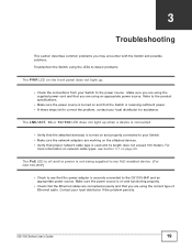
... my PoE-enabled device. (For GS1100-8HP) • Check to the product specifications. • Make sure the power source is turned on page 20. Troubleshoot the Switch using the LEDs to detect problems. The PWR LED on and functioning properly. • Check that the Ethernet cables are using the supplied power cord and that proper network cable type is receiving sufficient power. • If these steps fail to your Switch. • Make sure the network adapters are working on the attached devices. • Verify...
... my PoE-enabled device. (For GS1100-8HP) • Check to the product specifications. • Make sure the power source is turned on page 20. Troubleshoot the Switch using the LEDs to detect problems. The PWR LED on and functioning properly. • Check that the Ethernet cables are using the supplied power cord and that proper network cable type is receiving sufficient power. • If these steps fail to your Switch. • Make sure the network adapters are working on the attached devices. • Verify...
User Guide
Page 20
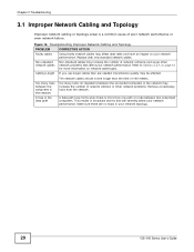
... GS1100 Series User's Guide Replace with new standard network cables. Refer to Section 2.2.4 on page 12 for more than one path or route between the connected computers in your network performance. If you use longer cables than the limit of network collisions and cause other network problems. Remove unnecessary hubs from the network. Chapter 3 Troubleshooting 3.1 Improper Network Cabling and Topology Improper network cabling or topology setup is more information on network cable types. Non-standard cables may...
... GS1100 Series User's Guide Replace with new standard network cables. Refer to Section 2.2.4 on page 12 for more than one path or route between the connected computers in your network performance. If you use longer cables than the limit of network collisions and cause other network problems. Remove unnecessary hubs from the network. Chapter 3 Troubleshooting 3.1 Improper Network Cabling and Topology Improper network cabling or topology setup is more information on network cable types. Non-standard cables may...

User Guide
Page 21
... (the Warranty Period) from any products, or software described herein. This device generates, uses, and can radiate radio frequency energy and, if not installed and used in material or workmanship for compliance could void the user's authority to radio communications. Taiwanese BSMI (Bureau of purchase. GS1100 Series User's Guide 21 Operation is subject to Part 15 of equal or higher value, and...
... (the Warranty Period) from any products, or software described herein. This device generates, uses, and can radiate radio frequency energy and, if not installed and used in material or workmanship for compliance could void the user's authority to radio communications. Taiwanese BSMI (Bureau of purchase. GS1100 Series User's Guide 21 Operation is subject to Part 15 of equal or higher value, and...

User Guide
Page 22
... stumble over Ethernet) devices that supply or receive power and their connected Ethernet cables must all cables from this device before servicing or disassembling. • Use ONLY an appropriate power adaptor or cord for your device. • Connect ONLY suitable accessories to the device. • Do NOT open the device or unit. Contact your vendor. Used electrical and electronic equipment should service or disassemble this warranty, contact your local vendor...
... stumble over Ethernet) devices that supply or receive power and their connected Ethernet cables must all cables from this device before servicing or disassembling. • Use ONLY an appropriate power adaptor or cord for your device. • Connect ONLY suitable accessories to the device. • Do NOT open the device or unit. Contact your vendor. Used electrical and electronic equipment should service or disassemble this warranty, contact your local vendor...

User Guide
Page 23
... Ethernet 10 F Faulty cables 20 FCC interference statement 21 Front Panel 9 GS1100 Series User's Guide Index Index Front Panel Connections 12 H High Power over Ethernet 8 I IEEE 802.3at 8 IEEE 802.3az 10 installation precautions 16 transceivers 10 L LED Descriptions LK/ACT 14 PWR 13, 14 Low Power Idle 10 LPI signal 10 M mounting brackets 16 N network cable crossover 12 straight-through 12 Network Cable Types 12 Non-standard network cables...
... Ethernet 10 F Faulty cables 20 FCC interference statement 21 Front Panel 9 GS1100 Series User's Guide Index Index Front Panel Connections 12 H High Power over Ethernet 8 I IEEE 802.3at 8 IEEE 802.3az 10 installation precautions 16 transceivers 10 L LED Descriptions LK/ACT 14 PWR 13, 14 Low Power Idle 10 LPI signal 10 M mounting brackets 16 N network cable crossover 12 straight-through 12 Network Cable Types 12 Non-standard network cables...

User Guide
Page 24
Index P PD 8 PoE 8 power supplying 8 Power over Ethernet 8 power saving 10 powered device 8 product registration 22 R rack mounting 15 Rear Panel 9 Rear Panel Power Connection 9 registration product 22 S safety warnings 22 Small Form-factor Pluggable (SFP) 10 Standalone Workgroup 7 T transceiver MultiSource Agreement (MSA) 10 transceivers 10 installation 10 removal 11 Troubleshooting Improper Network Cabling and Topology 20 W wall mounting 14 warranty 21 note 22 24 GS1100 Series User's Guide
Index P PD 8 PoE 8 power supplying 8 Power over Ethernet 8 power saving 10 powered device 8 product registration 22 R rack mounting 15 Rear Panel 9 Rear Panel Power Connection 9 registration product 22 S safety warnings 22 Small Form-factor Pluggable (SFP) 10 Standalone Workgroup 7 T transceiver MultiSource Agreement (MSA) 10 transceivers 10 installation 10 removal 11 Troubleshooting Improper Network Cabling and Topology 20 W wall mounting 14 warranty 21 note 22 24 GS1100 Series User's Guide


